7
SENR4955 February 1993
3
Part No.
B 14
C 1
12
18
4 9
15
Off Machine Switch Specification
Function
A
D 19
17 5
16
2
13
6
2
1
11
Deactuate
Contact Position
118.3°C MIN (245°F MIN)
Normally Closed
3T5825
Power Train Oil Temperature (EMS)
7N9785
Engine Coolant Temperature (EMS)
107.2 ± 2.8°C (225 ± 5°F)
91.0°C MIN (196°F MIN)
Normally Closed
7T0988
Engine Oil Pressure (EMS)
62 ± 21 kPa (9.0 ± 3.0 psi)
38 ± 21 kPa (5.0 ± 3.0 psi)
Normally Open
8N1693
Engine Coolant Temperature (Start Aid)
37.8 ± 2.8°C (100 ± 5°F)
26.7°C MIN (80°F MIN)
Normally Closed
8N2248
Hydraulic Oil Temperature (Differential Steer EMS)
101.7 ± 2.8°C (215 ± 5°F)
93.3°C MIN (200°F MIN)
Normally Closed
8T8639
Refrigerant Pressure (A/C)
344.5 ± 34.5 kPa (50 ± 5 psi)
172.3 ± 21 kPa (25 ± 3 psi)
Normally Open
9G1300
Hydraulic Oil Temperature (Clutch/Brake Steer EMS)
110.0 ± 2.8°C (230 ± 5.0°F)
101.7°C MIN (215°F MIN)
Normally Closed
9G3341
Power Train Oil Temperature (Clutch/Brake Steer EMS)
51.7 ± 2.8°C (125 ± 5°F)
43.0°C MIN (110°F MIN)
Normally Closed
9W3187
Fuel Pressure (EMS)
93 ± 21 kPa (13.5 ± 3.0 psi)
69 ± 21 kPa (10.0 ± 3.0 psi)
Normally Closed
9X7781
Power Train Filter Pressure (EMS) (Differential Steer EMS)
210 ± 70 kPa (30 ± 10 psi)
— —
Normally Open
8
10
Actuate
129.4 ± 2.8°C (265 ± 5°F)
D6H Series II Tractor Electrical System
D
Resistor, Sender and Solenoid Specifications
Part No.
A
10
8
16 C
7
4
11 5
3
B
2
1 18
1
9
Component Description
Resistance (Ohms)¹
2G0413
Resistor - Blower Motor Speed
5 Overall 2.0 ± .1 Tap 1.0±.05 50 ± 5.0
9G1950
Resistor - Blower Motor Speed
7X6416
Resistor - Load
6T2217
Resistor - Starter/Diagnostic Conn
150 ± 7.5
8T8813
Solenoid - A/C Clutch
14.4 ± 0.6
9G4365
Solenoid - Start Aid
6
¹ At room temperature unless otherwise noted.
2
17 14 12
15
19
13
Related Electrical Service Manuals
6
Title
Form Number
Alternator (1005047): Consist No.1005046
SENR2082
Consist No.1005045
SENR4130
Electronic Monitoring System
SENR2945
Starting And Charging Systems
SENR2947
4RC5500-UP 6FC5500-UP 8FC5500-UP 1KD5500-UP 2KD5500-UP 3ED5500-UP 3ZF5500-UP 4YF5500-UP 5HF5500-UP 6CF5500-UP 6CF5500-UP 2TG5500-UP
3YG5500-UP 4GG5500-UP 4LG5500-UP 1FJ5500-UP 8ZHJ1-UP 9KJ1-UP 2DK5500-UP 5KK1-UP 6CK1-UP 7ZK1-UP 8KK1-UP
8SK1-UP 9LK1-UP 9RK1-UP 1YL1-UP 2BL1-UP 2TL1-UP
Starting Motor (4N3181):
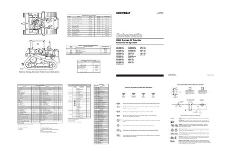
Machine Harness Connector And Component Locations
Consist No. 8C3651 (42-MT)
SENR3581
Consist No. 9X4447 (F8)
SENR4975
Consist No. 3T6305 (KE)
SENR3536
© 1993 Caterpillar All Rights Reserved
Component Alarm - Action (EMS)
Schematic Location D-8
Machine Location 1
Component Sender - Hydraulic Oil Temp (Gauge)
Schematic Location A-6
Machine Location 11
Alarm - Backup
E-9
C
Sender - Power Train Oil Temp (Gauge)
B-2
12
Alternator
B-1
2
Solenoid - A/C Clutch
B-2
13
Batteries
F-3
3
Solenoid - Start Aid
F-2
14
Breaker - Alternator (60A)
E-7
B
Switch - Backup Alarm (CBS)
D-7
C
Breaker - Blower Motor
F-5
B
Switch - Backup Alarm (DS)
E-7
C¹
Converter - Voltage
E-3
C
Switch - Blower Motor (A/C)
B-3
A
Filter - Alternator
B-5
A
Switch - Blower Motor (Heater)
C-3
5
Fuse - Front Dash and Dome (10A)
E-7
B
Switch - Disconnect
F-3
3
Fuse - Key (10A)
F-7
B
Switch - Engine Coolant Temp (EMS)
C-2
9
Fuses
E-6
B
Switch - Engine Coolant Temp (Start Aid)
D-2
9
Gauges
B-5
A
Switch - Engine Oil Pressure (EMS)
C-2
15
Ground - Module
D-4
A
Switch - Flood Lamp
B-6
A
Horns - Front
F-1
4
Switch - Forward Horn
B-6
16
Lamp - Action (EMS)
D-6
A
Switch - Front and Dash Lamp
C-6
A
Meter - Service
B-5
A
Switch - Fuel Press (EMS)
C-2
17
Monitor - Operator (EMS)
D-4
A
Switch - Hydraulic Oil Temp (EMS)
A-6
11
Motor - Blower (Heater)
B-3
5
Switch - Key Start
C-5
A
Motor - Starting
A-2
6
Switch - Neutral Start (DD)
B-9
18
Motor - Windshield Washer
A-8
7
Switch - Neutral Start (PS with DS)
D-7
C¹
Motors - Blower (A/C)
B-3, C-3
8
Switch - Neutral Start (PS with CBS)
D-7
C
Motors - Wiper (Front & Left)
C-4, E-7
D
Switch - Power Train Filter Press (DS EMS)
A-6
11
Motors - Wiper (Rear & Right)
C-8, B-6
D
Switch - Power Train Oil Temp (CBS EMS)
C-2
19
Radios (12V & 24V)
B-4
D¹
Switch - Power Train Oil Temp (EMS)
C-2
12
Relay - Main (Replaces Terminal Block)
F-8
B
Switch - Refrigerant Press
F-2
13
Relay - Start
F-6
B
Switch - Start Aid
C-6
A
Resistor - Blower Motor Speed (A/C)
B-3
8
Switch - Test (EMS)
D-6
A
Resistor - Blower Motor Speed (Heater)
B-3
5
Switch - Thermostat (A/C)
B-3
A
Resistor - Load
F-6
B
Switches - Wiper
B-7, B-8
D¹
Resistor - Starter to Diagnostic Connector
B-2
6
Terminal Block
F-6
B
Sender - Engine Coolant Temp (Gauge)
C-2
9
Sender - Fuel (Gauge)
D-9
10
Connector
Machine Location
8 Contacts
7Contacts
* B
A - 6Y7376 Diagnostic Connector
F-7
A
A - 6Y7376 C - 7T8326
D-6
D¹
G - 9U9458 Attachment H - 9U9463 Attachment
D¹
G - 9U9458 Attachment H - 9U9463 Attachment
D¹
G - 9U9458 Attachment Radio
1
A - 6Y7376 B-1011339
1
6 Contacts
5 Contacts
A - 6Y7376 B-1011339
EMS = Electronic Monitoring System (operator monitor)
together.
DS = Differential Steer Machines
A = Components in dash area.
CBS = Clutch/Brake Steer Machines
B = Components at relay panel.
PS = Power Shift
C = Components in operator's left console.
PT = Power Train
C ¹ = Components within diff steer control handle of operator's left console. D = Components in operator compartment. D ¹ = Components in headliner of operators compartment.
C-7 C-B B-4
D-3 A-5
*
A - 6Y7376 Voltage Converter
E-3
A
A - 6Y7376 M-6I8611
B-5
A
A-6Y7376 C-7T8326
A
A-6Y7376 G - 9U9458 Attachment
D-6
A
A - 6Y7376 N - 9W1816 Attachment
C-3
A
A - 6Y7376 Y - 6Y3416 Attachment
4 Contacts
Wire Number
Wire Color
101
RD
BAT
102
BU
HD LMP
105
BR
KEY SW
108
BU
AUX CKT
109
OR
ALT OUTPUT(+) TERM.
112
PU
MAIN POWER RELAY OUTPUT
113
OR
OPR MON PANEL B+ SWITCHED
114
GN
WARNING HORN (FORWARD)
116
BR
AUX CKT
121
YL
BACKUP ALARM TO LAMP
123
WH
AUX CKT
124
GN
A/C
129
BU
AUX CKT
D-5
C-3
Description Power Circuits
Ground Circuits 200
BK
MAIN CHASSIS
201
BK
OPR MON PANEL CMS
203
BK
CHASSIS DIAGNOSTIC
207
BK
STARTER DIAGNOSTIC
301
BU
STARTER NO.1 SOL
302
OR
STARTER NO.1 RESISTOR TO DIAGNOSTIC
304
WH
STARTER RELAY NO.1 OUTPUT
306
GN
STARTER RELAY COIL TO NEUT START SW
307
OR
KEY SW TO NEUT START SW
308
YL
MAIN POWER RELAY COIL
310
PU
START AID SW TO START AID SOL
311
WH
START AID SOL TO TEMP SW
321
BR
BCKP ALARM LAMP
322
GY
WARNING HORN (FORWARD)
403
GN
ALTERNATOR (R) TERM.
404
YL
OPR MON HYD OIL TEMP
405
GY
OPR MON OIL PRESS. (LO SETTING)
406
PU
OPR MON COOLANT TEMP
410
WH
OPR MON ACTION ALARM
411
PK
OPR MON ACTION LAMP
413
BR
OPR MON FUEL PRESS.
415
GN
OPR MON TEST SW
424
GY
OPR MON POWER TRAIN TEMP
426
BR
OPR MON POWER TRAIN OIL FILTER
E-3
A - 6Y7376 E - 9U9407
A
AA
2
T
Pressure Symbol
Temperature Symbol
OR
ENG COOLANT TEMP GAGE
442
GY
HYD SYSTEM TEMP GAGE
* = Connector is located at the component.
443
YL
POWER TRAIN TEMP GAGE
447
PK
FUEL LEVEL GAGE Accessory Circuits
500
BR
WIPER - FRONT (PARK)
501
GN
WIPER - FRONT (LO)
502
OR
WIPER - FRONT (HI)
503
BR
WIPER - REAR (PARK)
504
YL
WIPER - REAR (LO)
505
BU
WIPER - REAR (HI)
508
PU
RADIO SPEAKER - LEFT
509
WH
RADIO SPEAKER - LEFT (COMMON)
510
YL
WASHER - PRIMER
511
BR
RADIO SPEAKER - RIGHT
512
GN
RADIO SPEAKER - RIGHT (COMMON)
513
OR
A/C COMPRESSOR/REFRIGERANT PRESS. SW
515
GY
BLOWER MOTOR (HI)
516
GN
BLOWER MOTOR (MEDIUM)
517
BU
BLOWER MOTOR (LO)
521
YL
A/C SW TO REFRIGERANT SW
522
WH
A/C CLUTCH TO THERMOSTAT SW
523
BR
WIPER - LEFT (PARK)
524
BU
WIPER - LEFT (LO)
525
GY
WIPER- LEFT (HI)
526
YL
WIPER - RIGHT (PARK)
527
GN
WIPER - RIGHT (LO)
528
PK
WIPER - RIGHT (HI)
592
BU
DC/DC CONVERTER POWER OUTPUT
A513
PK
DC/DC CONVERTER MEMORY OUTPUT
600
BR
DASH BASIC
608
GN
FLOOD REAR
609
YL
FLOOD SIDE
610
OR
HEAD LAMP BASIC
Lighting Circuits
Typical representation of a Deutsch connector. The plug contains all sockets and the receptacle contains all pins.
Receptacle
Plug
Level Symbol
Flow Symbol
1 2
1 2
1
Typical representation of a Sure-Seal connector. The plugand receptacle contain both pins and sockets.
Pin or Socket Number Wire, Cable, or Harness Assembly Identification
Component Part Number
Single Wire Connector
Normally open switch that will close with an increase of a specific condition (temp-press-etc.).
C
A
A 325-PK-14
Pin
Normally open switch that is closed due to an applied condition, and will open again with a specific decrease in that condition.
Monitoring Circuits
441
A = Connector in dash area.
Electrical Schematic Symbols And Definitions
Basic Machine Circuits
Machine locations are repeated for connectors located close together.
D ¹ = Connector in headliner of operators compartment.
Machine locations are repeated for components located close
E-4
2
B = Connector at relay panel.
A/C = Air Conditioning
Schematic Location
A-6Y7376 Operator Monitor (EMS)
20 Contacts
9 Contacts
Harness And/Or Components
Harness And Wire Electrical Schematic Symbols
Wire Description
Harness Connector Location Chart
Component Location
Printed in U.S.A.
AA 1
325-PK-14
Wire Color
Socket
2
Normally closed switch that will open with an increase of a specific condition.
9X-1123
200-BK-14
Circuit Number Identification
Normally closed switch that is open due to an applied condition, and will close again with a specific decrease in that condition.
Wire Gauge
Electrical Schematic Symbols And Definitions FUSE - A component in an electrical circuit that will open the circuit if too much current flows through it.
The circle indicates that the component has screw terminals and a wire can be disconnected from it.
REED SWITCH - A switch whose contacts are controlled by a magnet. A magnet closes the contacts of a normally open reed switch; it opens the contacts of a normally closed reed switch.
No circle indicates that the wire cannot be disconnected from the component. T
This indicates that the component has a wire connected to it that is connected to ground.
This indicates that the component does not have a wire connected to ground. It is grounded by being fastened to the machine.
SENDER - A component that is used with a temperature or pressure gauge. The sender measures the temperature or pressure. Its resistance changes to give an indication to the gauge of the temperature or pressure. RELAY (Magnetic Switch) - A relay is an electrical component that is activated by electricity. It has a coil that makes an electromagnet when current flows through it. The electromagnet can open or close the switch part of the relay. CIRCUIT BREAKER (C/B) - A component in an electrical circuit that will open the circuit if too much current flows through it. This does not destroy the circuit breaker and it can be reset to become part of the circuit again. SOLENOID - A solenoid is an electrical component that is activated by electricity. It has a coil that makes an electromagnet when current flows through it. The electromagnet can open or close a valve or move a piece of metal that can do work. MAGNETIC LATCH SOLENOID - A magnetic latch solenoid is an electrical component that is activated by electricity and held latch by a permanent magnet. It has two coils (latch and unlatch) that make electromagnet when current flows through them. It also has an internal switch that places the latch coil circuit open at the time the coil latches.