Component Location
Alarm - Action
Schematic Location B-8
Alarm - Backup
E-9
1
Sender - Fuel
D-9
7
Alternator
B-2
2
Sender - Tachometer
A-6
8
Batteries
F-4
3
Sender - Torque Converter Oil Temperature
C-4
9
Breaker - Alternator
F-9
B
Solenoid - Start Aid
E-2
10
Electronic Monitoring System (EMS)
E-6
A
Solenoid - Variable Horsepower
A-9
11
Filter - Alternator
C-6
A
Suppressor - Arc
A-9
11
E-8,F-7
B
Switch - Backup Alarm
E-8
C
Gauge - Coolant Temperature
B-6
A
Switch - Coolant
C-2
6
Gauge - Fuel Level
B-6
A
Switch - Disconnect
F-4
C
Gauge - Torque Converter Temperature
B-6
A
Switch - Engine Oil Pressure
C-3
6
Component
Fuses
Machine Location D
Component Sender - Coolant Temperature
Schematic Location C-3
Machine Location 6
Ground
A-8
4
Switch - Flood Lamp
C-8
A
Ground
B-2
2
Switch - Forward Horn
B-7
D
Ground - Frame
A-3
4
Switch - Front/Dash Lamp
C-8
A
Ground - Frame
F-4
C
Switch - Fuel Pressure
C-3
12
Ground - Module
D-6
A
Switch - Hydraulic Oil Temperature
D-9
13
Ground - Opr Monitor Panel Mounting Bolt
C-7
A
Switch - Key Start
D-7
A
Horn - Front
F-1
5
Switch - Neutral Start
D-8
C
Lamp - Master Action
D-7
A
Switch - Neutral Start
E-8
C
Lamp - Variable Horsepower Indicator
B-7
A
Switch - Operator Monitor Test
D-7
A
Meter - Service
B-6
A
Switch - Start Aid
D-8
A
Motor - Starter
B-3
4
Switch - Start Aid Temperature
E-2
10
Relay - Main
F-8
B
Switch - Transmission
A-4
14
Relay - Start
F-8
B
Tachometer
B-6
A
Resistor - Starter/Diagnostic
B-3
4
SENR8379 October 1996 D78394
15 D
8 5
4
2
14
12 3
11 7
A 10 9
17
6
B
C 13 16
1
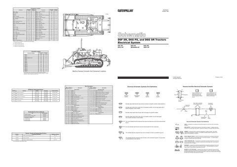
D6F SR, D6G PS, and D6G SR Tractors Electrical System
Machine locations are repeated for components located close together. A = Located in the dash area. B = Located in the relay panel area. C = Located in the left console area.
D6F SR: 5FR1-UP
D = Located in the right console area.
1
Schematic Location
Machine Location
CONN 1
A-9
15
CONN 2
C-9
15
CONN 3
E-9
16
Connector Number
D6G SR: 3SR1-UP
7
A
Connector Location
D6G PS: 2MJ02654-UP
CONN 4 Diagnostic Conn
F-9
B
CONN 5
E-8
C
CONN 6
D-8
C
CONN 7
D-8
A
CONN 8
B-7
A
CONN 9
D-7
A
CONN 10
C-6
A
CONN 11
A-5
14
CONN 12
A-4
4
CONN 13
C-4
10
CONN 14
E-3
17
CONN 15
D-3
17
CONN 16
D-3
17
CONN 17
F-2
5
C
10
D
B
12
13
6
5 2
17
1 16 15
4 8
9
11 14
3
Machine Harness Connector And Component Locations
1 The
connectors shown in this chart are for harness to harness connectors. Connectors that join a harness to a component are generally located at or near the component. See the Component Location Chart.
Printed in U.S.A.
© 1996 Caterpillar All Rights Reserved
Part No.
Function
Off Machine Switch Specification
Wire Color
101
RD
102 105
Wire Description Wire Number
Wire Color
Battery (+)
403
GN
Alternator (R) Terminal.
BU
Head Lamp
404
YL
Operator Monitor Hydraulic Oil Temperature
BR
Key Switch
405
GY
Operator Monitor Oil Pressure (Lo Setting)
108
BU
Auxiliary Circuit
406
PU
Operator Monitor Coolant Temperature
109
OR
Alternator Output (+) Terminal.
410
WH
Operator Monitor Action Alarm
112
PU
Main Power Relay Output
411
PK
Operator Monitor Action Alarm Lamp
113
OR
Operator Monitor Panel B (+) Switched
413
BR
Operator Monitor Fuel Pressure
114
GN
Warning Horn (Forward)
415
GN
Operator Monitor Test Switch
116
BR
Auxiliary Circuit
428
OR
Operator Monitor Transmission Oil Temperature
121
YL
Backup Alarm to Lamp
439
YL
Lamp Indicator
123
WH
Auxiliary Circuit
441
OR
Engine Coolant Temperature Gauge
145
BU
Auxiliary Circuit
443
YL
Power Train Temperature Gauge
447
PK
Fuel Level Gauge
450
YL
Tachometer Sender (+)
Description Power Circuits
Actuate
Deactuate
Contact Position
3E-6425
Start Aid Temperature
38.00 ± 3.0°C (100.4° ± 5.4°F)
27.0 °C MIN (80.6°F MIN)
Normally Closed
7N-9785
Coolant Temperature
107.2 ± 2.8°C (225.0 ± 5.0°F)
93.0°C MIN (200°F MIN)
Normally Closed
Hydraulic Oil Temperature
101.7°C MIN (215.0°F MIN)
93.3°C MIN (200°F MIN)
Normally Closed
107-0613
Engine Oil Pressure
62 ± 21 kPa (9.0 ± 3.0 psi)
38 ± 21 kPa (5.5 ± 3.0 psi)
Normally Open
107-0616
Fuel Pressure
93 ± 21 kPa (13.5 ± 3.0 psi)
69.0 ± 21 kPa (10.0 ± 3.0 psi)
Normally Closed
8N-2248
Wire Number
Ground Circuits
Title
Form Number
Alternator: 6N-9294
SENR4130
Electronic Monitoring System (EMS)
SENR2945
Starting and Charging Systems Starting Motor: 106-8555 Consist: 6V-5023 Consist: 6V-5207 Consist: 6V-5226
SENR2947 SENR3536 SENR3581 SENR4975
Monitoring Circuits
200
BK
Main Chassis
201
BK
Operator Monitor Panel
203
BK
Chassis Diagnostic
600
BR
Dash Lamp Basic
207
BK
Starter Diagnostic
607
PK
Flood Lamp - Front
608
GN
Flood Lamp - Rear
788
YL
Engine Speed (+)
Basic Machine Circuits
Related Electrical Service Manuals
Description
301
BU
Starter No. 1 Solenoid
302
OR
Starter No. 1 Resistor to Diagnostic
304
WH
Starter Relay No. Output
306
GN
Starter Relay Coil to Neutral Start Switch
307
OR
Key Switch to Neutral Start Switch
308
YL
Main Power Relay Coil
310
PU
Start Aid Switch to Start Aid Solenoid
311
WH
Start Aid Solenoid to Temperature Switch
321
BR
Backup Alarm Lamp
322
GY
Warning Horn (Forward)
Harness And Wire Electrical Schematic Symbols
Electrical Schematic Symbols And Definitions
Lighting Circuits
Control Circuits
A
T
Pressure Symbol
Temperature Symbol
Level Symbol
Flow Symbol
Resistor, Sender and Solenoid Specifications Component Description
6T-2217
Resistor - Starter/Diagnostic Conn
9G-4365
Solenoid - Start Aid
104-9258
Solenoid - Variable Horsepower
2
¹ At room temperature unless otherwise noted.
Typical representation of a Sure-Seal connector. The plugand receptacle contain both pins and sockets.
Wire, Cable, or Harness Assembly Identification
Normally open switch that will close with an increase of a specific condition (temp-press-etc.).
Component Part Number
Single Wire Connector
Normally open switch that is closed due to an applied condition, and will open again with a specific decrease in that condition.
C
A
A 325-PK-14
Pin
AA 1
2
Normally closed switch that is open due to an applied condition, and will close again with a specific decrease in that condition.
9X-1123 325-PK-14
Wire Color
Socket
Normally closed switch that will open with an increase of a specific condition.
200-BK-14
Circuit Number Identification
The circle indicates that the component has screw terminals and a wire can be disconnected from it.
Wire Gauge
Electrical Schematic Symbols And Definitions FUSE - A component in an electrical circuit that will open the circuit if too much current flows through it.
Resistance (Ohms)¹ 150 ± 7.5
21.7 ± 2.8
Typical representation of a Deutsch connector. The plug contains all sockets and the receptacle contains all pins.
Pin or Socket Number
This indicates that the component has a wire connected to it that is connected to ground.
6.0
1 2
1 2
Receptacle
Plug
No circle indicates that the wire cannot be disconnected from the component.
Part No.
AA 1
This indicates that the component does not have a wire connected to ground. It is grounded by being fastened to the machine.
REED SWITCH - A switch whose contacts are controlled by a magnet. A magnet closes the contacts of a normally open reed switch; it opens the contacts of a normally closed reed switch.
T
SENDER - A component that is used with a temperature or pressure gauge. The sender measures the temperature or pressure. Its resistance changes to give an indication to the gauge of the temperature or pressure. RELAY (Magnetic Switch) - A relay is an electrical component that is activated by electricity. It has a coil that makes an electromagnet when current flows through it. The electromagnet can open or close the switch part of the relay. CIRCUIT BREAKER (C/B) - A component in an electrical circuit that will open the circuit if too much current flows through it. This does not destroy the circuit breaker and it can be reset to become part of the circuit again. SOLENOID - A solenoid is an electrical component that is activated by electricity. It has a coil that makes an electromagnet when current flows through it. The electromagnet can open or close a valve or move a piece of metal that can do work. MAGNETIC LATCH SOLENOID - A magnetic latch solenoid is an electrical component that is activated by electricity and held latch by a permanent magnet. It has two coils (latch and unlatch) that make electromagnet when current flows through them. It also has an internal switch that places the latch coil circuit open at the time the coil latches.