WIRE DESCRIPTION CHART
SENR5313 August 1993
Off Machine Switch Specification Part No.
14
24
6
22
Function
23
D
12
8
8
C
19
4
7
1
A
10
15 9
25
21
5
2
14
WIPER - FRONT (HI)
KEY SW
503
BR
WIPER - REAR (PARK)
3E-7504
Trans Oil Temp
107.0 ± 3.0°C (225.0 ± 5.0°F)
98.0°C MIN (208.0°F MIN)
Normally Open
106
WH
AUX CKT
504
YL
WIPER - REAR (LO)
A-B, Normally Open A-C, Normally Closed
ENG SHUTDOWN
508
PU
RADIO SPEAKER - LEFT
Differential Lube Pressure
35.0 ± 21.0 kPa (5.0 ± 3.0 psi)
WH
3E-7674
90.0 kPa MAX (13.0 psi Max)
107 109
OR
ALT OUTPUT (+) TERM.
509
WH
RADIO SPEAKER - LEFT (COMMON)
MAIN POWER RELAY OUTPUT
511
BR
RADIO SPEAKER - RIGHT
Engine Oil Pressure
38.0 ± 10.0 kPa (6.0 ± 1.5 psi)
PU
101-3780
80.0 kPa MAX (12.0 psi MAX)
112
Normally Closed
115
PK
AUX CKT
512
GN
RADIO SPEAKER - RIGHT (COMMON)
262.0 ± 20.0 kPa (38.0 ± 3.0 psi)
BR
AUX CKT
513
OR
Transmission Pressure
310.0 kPa MAX (45.0 psi MAX)
116
Normally Closed
118
GY
AUX CKT
515
GY
A/C COMPRESSOR/REFRIGERANT PRESS. SW BLOWER MOTOR (HI)
Engine Coolant Temp
108.0± 3.0°C (226.0 ± 5.0°F)
100.0°C MIN (212.0°F MIN)
Normally Open ¹
119
PK
AUX CKT
516
GN
BLOWER MOTOR (MEDIUM)
123
WH
AUX CKT
518
OR
HAZARD FLASHER TO SW
Hydraulic Oil Temp
82.0 ± 3.0°C (180.0 ± 5.0°F)
74.0°C MIN (165.0°F MIN)
Normally Open ¹
124
GN
A/C
521
YL
A/C SW TO REFRIGERANT SW
130
GN
AUX CKT
522
WH
A/C CLUTCH TO THERMOSTAT SW
135
BU
AUX CKT
539
BU
TURN SIGNAL INDICATOR BASIC/RIGHT
150
OR
EUI (ADEM)
540
WH
153
WH
3 PT HITCH CONT
557
YL
165
YL
AUX CKT
558
GN
TURN SIGNAL INDICATOR LEFT TRAILER CONNECTOR (LEFT TURN/HAZARD) TRAILER CONNECTOR (RIGHT TURN/HAZARD)
167
OR
AUX CKT
568
GN
169
PK
AUX CKT
594
PU
170
YL
AUX CKT
595
YL
172
GN
AUX CKT
596
WH
175
PK
AUX CKT Ground Circuits
604
OR
STOP LAMP
200
BK
MAIN CHASSIS
605
YL
TURN LAMP - LEFT
201
BK
OPR MON PANEL
606
GY
TURN LAMP - RIGHT
229
BK
EUI CONT
607
PK
FLOOD LAMP - FRONT
A220
BK
DRAFT CONTROL IDENT CODE 0
610
OR
HEAD LAMP BASIC
611
PU
HEAD LAMP HI
¹ To check contact position of switch measure from Contact 2 to case.
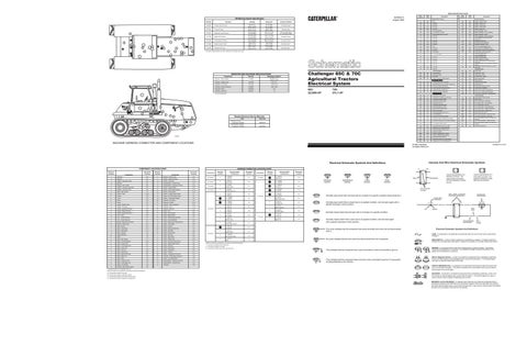
Challenger 65C & 70C Agricultural Tractors Electrical System
Part No.
Resistance (Ohms)¹
Resistor - Blower Speed
7T-3828
Overall1.0 ± 0.1 Tap 0.5 ± 0.05
Resistor - Flasher Load
3E-0108
8.0 ± 0.4
Solenoid - A/C Clutch
3E-1907
3.50 ± 0.15
Solenoid - Dual Horsepower
104-9257
5.40 ± 0.50
Solenoid - Hitch
100-3915
6.2
Solenoid - Start Aid
3E-6331
1.5
65C: 2ZJ500-UP
Basic Machine Circuits
70C: 2YL1-UP
7
8
3
23
13 1
C
25
6
CHALLENGER
19
1
15 9
20 11
21
Related Electrical Service Manuals
5
24
3
22
4
2
WIPER - FRONT (LO)
BR
A
5
WIPER - FRONT (PARK)
GN
105
¹ At room temperature.
B
BR
501
OR
D
16
500
HD LMP
502
7
6
BAT
BU
AUX CKT
Component
4
RD
102
YL
B
8
101 104
RESISTOR AND SOLENOID SPECIFICATIONS
12
2
10 17 18
Title
Form No.
Alternator (21 SI): Consist No. 9X-9096
SENR4757
Starting Motor (42-MT): Consist No. 3E-7864
SENR3581
C48654P1
MACHINE HARNESS CONNECTOR AND COMPONENT LOCATIONS
Component
Machine Location
WH
STARTER RELAY NO.1 OUTPUT
614
PU
PARK/TAIL/DASH LAMP
306
GN
STARTER RELAY COIL TO NEUT START SW
619
GN
HEAD LAMP LO
307
OR
KEY SW TO NEUT START SW
630
GY
FLOOD LAMP REAR (ATTACH)
310
PU
START AID SW TO START AID SOL
635
BR
TURN SIGNAL COMMON
311
WH
START AID SOL TO TEMP SW
647
GN
LIGHT SW TO REAR FLOOD RELA Y
322
GY
WARNING HORN (FORWARD)
648
BU
LIGHT SW TO HEADLAMP BREAKER
Monitoring Circuits
649
YL
LIGHT SW TO PARK/TAIL LAMP BREAKER
GN
XMSN SPEED PICKUP SIGNAL
Component
1
Alternator
B-2
C
Resistor - Flasher Load
E-5
2
Batteries
B-1
11
Sender - Engine Oil Press
E-2
3
Breaker - Alternator (135A)
B-2
12
Sender - Fuel Level
2
Batteries
B-1
13
Sender/Switch - Coolant Temp
3
Breaker - Main (135A)
B-3
14
Sender/Switch - Hydraulic Oil Temp
C
Breaker - Running Lamp (20A)
E-6
15
Sensor - Engine Speed
C
Breaker - Tail Lamp (10A)
E-6
B
Sensor - Hitch Handle Position
C-10 B-12
C-12 E-2 C-12 E-2
4
Buffer - Belt Tension
C-2
16
Sensor - Hitch Position
B
Control - Draft
B-10
17
Sensor - LH Belt Tension Press
F-1
C
Flasher
E-5
18
Sensor - RH Belt Tension Press
B-2
C
Fuses
D-5
19
Sensor - Transmission Speed
A-6
C
Fuses
E-6
20
Solenoid - A/C Clutch
D-2
C
Fuses
F-6
D
Solenoid - Air Seat
D-10
A
Gauge - Coolant Temp
D-9
21
Solenoid - Dual Horsepower ¹
D-3
A
Gauge - Fuel Level
C-9
16
Solenoid - Hitch
A-12
A
Gauge - Hydraulic Oil Temp
C-9
22
Solenoid - Start Aid
D-2
A
Gauge - Engine Oil Press
D-9
A
Switch - A/C
B-9
A
Gauge - Speed/Tach/Ser Hr
D-9
13
Switch - A/C Pressure
D-2
A
Horn - Alarm
D-5
A
Switch - Blower Motor
B-9
5
Horn - Foward Warning
D-2
23
Switch - Differential Lube Press
A-7
5
Horn - Foward Warning
E-1
B
Switch - Draft On/Off/Set
B-10
A
Monitor - Electronic Control Gp
C-7
13
Switch - Eng Coolant Temp (St Aid)
D-3
A
Monitor - Performance
E-11
A
Switch - Front Wiper
6
Motor - Blower
B-4
B
Switch - Hookup
7
Motor - Front Wiper
D-4
24
Switch - Hydraulic Filter Flow
F-2
8
Motor - Rear Wiper
D-11
D
Switch - Key Start
B-6
9
Motor - Starting
C-3
B
Switch - Neutral Start
B-8
10
Radar (Perf Mon)
A-5
11
Switch - Oil Press
E-2
D
Radio
C-4
A
Switch - Rear Wiper
E-9
C
Relay - Belt Tension
F-7
A
Switch - Rotary Light
E-10
B
Relay - Dual Horsepower ¹
B-10
D
Switch - Running Lamp Dimmer
B-7
C
Relay - Foward Horn
E-7
A
Switch - Signal (Gage Cluster)
D-9
C
Relay - Front Flood Lamp
E-7
A
Switch - Start Aid
F-9
C
Relay - Lamp Test
F-7
C
Switch - Stop Lamp
B-6
C
Relay - Left Turn
E-5
6
Switch - Thermostat
B-4
3
Relay - Main Power
B-3
B
Switch - Throttle
C
Relay - Rear Flood Lamp
E-7
25
Switch - Transmission Oil Temp
A-6
C
Relay - Right Turn
E-5
19
Switches - Transmission Pressure 1
A-8
3
Relay - Start
A-2
D
Switch - Turn/Hazard/Horn
F-8
C
Relay - Trailer Left Turn
E-5
14
Switch/Sender - Hydraulic Oil Temp
C
Relay - Trailer Right Turn
F-5
13
Switch/Sender - Coolant Temp
E-2
C
Relays - Front Wiper
D-6
A
Voltmeter
D-9
6
Resistor - Blower Motor Speed
B-4
¹ Components used on Challenger 70C only. Machine locations are repeated for components located close together. A = Components located in the dash. B = Components located in right side console. C = Components located under dash near floor level. D = Components located in operator's compartment.
Connectors 40 Contacts
YL
OPR MON HYD OIL TEMP
405
GY
OPR MON OIL PRESS. (LO SETTING)
710
406
PU
OPR MON COOLANT TEMP
795
YL
DUAL HP SOL
410
WH
OPR MON ACTION ALARM
870
OR
3 PT HITCH CONT - DOWN SOL
415
GN
OPR MON TEST SW
871
BU
3 PT HITCH CONT - SOL COMMON
419
YL
OPR MON PARKING BRAKE
872
YL
3 PT HITCH CONT - UP SOL
428
OR
OPR MON XMSN OIL TEMP
888
PK
3 PT HITCH CONT - HITCH POSITION
441
OR
ENG COOLANT TEMP GAGE
889
GY
3 PT HITCH CONT - HANDLE POSITION
447
PK
FUEL LEVEL GAGE
890
PU
3 PT HITCH CONT - HOOKUP SW
449
BU
SPDOM SENDER (SIGNAL NO. 1)
917
WH
DUAL HP RELAY TO SW
450
YL
TACH SENDER (+)
B995
GY
3 PT HITCH CONTROL - DRAFT OFF /ON
457
PU
OPR MON SYSTEM AIR PRESS
B996
BR
3 PT HITCH CONTROL - SET POINT
459
PK
OPR MON PANEL IMPLEMENT POSITION
B997
PK
464
GY
OPR MON PANEL ENG OIL PRESS. SENSOR
B995
GY
465
OR
LO CHARGE PRESS. ALERT
B997
PK
3 PT HITCH DRAFT SWITCH TO THROTTLE SWITCH
466
WH
OPR MON PANEL STER OIL TEMP
C912
GN
THROTTLE POSITION
471
PK
XMSN NEUT TO PARKING BRAKE
477
YL
SPDOM SENDER (SIGNAL NO. 2)
497
BU
SENSOR POWER
A424
WH
PRESS. TRANSDUCER 1 SIGNAL
A425
YL
PRESS. TRANSDUCER 2 SIGNAL
A430
OR
EUI CONT FAULT OUTPUT
B402
YL
INDICATOR LAMP DIFF LUBE PRESS.
B437
BR
HYDRAULIC OIL FILTER INDICATOR
C
Harness And/Or Components E - 1065570 F - 9U3175
Schematic Location
Connectors
Machine Location
Harness And/Or Components
3 PT HITCH DRAFT SWITCH TO THROTTLE SWITCH 3 PT HITCH CONTROL - DRAFT OFF/ON
Printed in U.S.A.
E - 1065570 Trailer Conn
D-12
1
D - 1075685 E - 1065570
D-2
E-11
5
E - 1065570 H - 9U3177
A-12
E-4
7 Contacts
4
*
15 Contacts
*
Q - 9U3645 Monitor Panel
14 Contacts
*
F - 9U3175 Turn/Haz/Horn Sw
F-8
6
E - 1065570 K - 9U3182
F-12
A
C - 9U3173 F - 9U3175
B-5
7
F - 9U3175 R - 1018767
B-4
1
D - 1075685 E - 1065570
E-3
*
C - 9U3173 Rear Wiper Motor
D-11
2
E - 1065570 S - 1065569
C-2
*
F - 9U3175 Frt Wiper Sw
B-7
6 Contacts
A
F - 9U3175 P - 9U3174
B-5
*
F - 9U3175 Rotary Light Sw
E-10
A
F - 9U3175 N - 9U2706
D-8
*
P - 9U3174 Frt Wiper Motor
D-4
A
F - 9U3175 Q - 9U3645
8
E - 9U3176 J - 9U3179
C-12
*
E - 9U3176 Radar Unit
A-5
12 Contacts
8 Contacts
B-10
E-10 4 Contacts
*
F - 9U3175 Monitor Panel
C-7
*
Q - 9U3645 Performance Monitor
E-11
3
A - 9U3196 B - 9U3197
A-11
*
F - 9U3175 Monitor Panel
C-7
*
S - 1065569 Belt Tension Buffer
C-2
*
P - 9U3174 Radio
C-4
AA
T
Pressure Symbol
Temperature Symbol
Level Symbol
Flow Symbol
Typical representation of a Deutsch connector. The plug contains all sockets and the receptacle contains all pins.
Receptacle
Plug
1 2
1 2
1
Schematic Location
24 Contacts
B-7
C-12
Machine Location
A
A - 9U3196 Draft Control
C-11
C-11
Control Circuits
404
Harness And Wire Electrical Schematic Symbols
HARNESS CONNECTOR LOCATION CHART Schematic Location
FRONT WIPER SW (B) TO HI SPD RELAY COIL (85) FRNT WPR SW(C) TO HI SPD RELAY(30) & LO SPD(85) FRNT WPR HI SPD RELAY(87) TO LO SPD RELAY(87) Lighting Circuits
© 1993 Caterpillar All Rights Reserved
COMPONENT LOCATION CHART Schematic Location
ALERT BUZZER TO DIODES
304
Electrical Schematic Symbols And Definitions Machine Location
Description Accessory Circuits
Normally Closed
107-4927 5
1
18
3
3
20
2
Power Distribution Circuits
27.0°C MIN (81.0°F MIN)
107-4658 4
Wire Color
38.0± 3.0°C (100.0 ± 5.0°F)
103-4976
6
7
Contact Position
Wire Number
Description
Coolant Temp (St Aid)
17
13
Deactuate
Wire Color
3E-6425
11
16
Actuate
Wire Number
2
Typical representation of a Sure-Seal connector. The plugand receptacle contain both pins and sockets.
Pin or Socket Number Wire, Cable, or Harness Assembly Identification
Normally open switch that will close with an increase of a specific condition (temp-press-etc.).
Component Part Number
Single Wire Connector
Normally open switch that is closed due to an applied condition, and will open again with a specific decrease in that condition.
C
A
A 325-PK-14
Pin
AA 1
Wire Color
Socket
Normally closed switch that will open with an increase of a specific condition. 2
Normally closed switch that is open due to an applied condition, and will close again with a specific decrease in that condition.
9X-1123 325-PK-14
200-BK-14
Circuit Number Identification
Wire Gauge
Electrical Schematic Symbols And Definitions
The circle indicates that the component has screw terminals and a wire can be disconnected from it.
FUSE - A component in an electrical circuit that will open the circuit if too much current flows through it.
No circle indicates that the wire cannot be disconnected from the component.
REED SWITCH - A switch whose contacts are controlled by a magnet. A magnet closes the contacts of a normally open reed switch; it opens the contacts of a normally closed reed switch.
Machine locations are repeated for connectors located close together. * = Connector is located at the component. A = Connectors located in the dash. C = Connectors located under dash near floor level.
This indicates that the component has a wire connected to it that is connected to ground.
This indicates that the component does not have a wire connected to ground. It is grounded by being fastened to the machine.
T
SENDER - A component that is used with a temperature or pressure gauge. The sender measures the temperature or pressure. Its resistance changes to give an indication to the gauge of the temperature or pressure. RELAY (Magnetic Switch) - A relay is an electrical component that is activated by electricity. It has a coil that makes an electromagnet when current flows through it. The electromagnet can open or close the switch part of the relay. CIRCUIT BREAKER (C/B) - A component in an electrical circuit that will open the circuit if too much current flows through it. This does not destroy the circuit breaker and it can be reset to become part of the circuit again. SOLENOID - A solenoid is an electrical component that is activated by electricity. It has a coil that makes an electromagnet when current flows through it. The electromagnet can open or close a valve or move a piece of metal that can do work. MAGNETIC LATCH SOLENOID - A magnetic latch solenoid is an electrical component that is activated by electricity and held latch by a permanent magnet. It has two coils (latch and unlatch) that make electromagnet when current flows through them. It also has an internal switch that places the latch coil circuit open at the time the coil latches.