Part No.
Off Vehicle Switch Specifications
Function
Actuate
7N7854
Transmission Oil Temp
7X6212
Brake Accumulator Press
8C9969
Implement Hydraulic Oil Temp (Perf Mon)
8N1693
Engine Coolant Temp (Start Aid)
8T9705
Steering Oil Temp (Perf Mon)
9X5322
123.89 ± 2.78°C (255 ± 9°F) 5850 kPa (850 psi) 101 .67 ± 2.78°C (212 ± 37.5°F 37.8 ± 2.8°C (100 ± 5°F) 82.22 ± 2.78°C (180 ± 9°F) 90 kPa Max (13 psi)
Differential Lube Press
* = Pins 1-2 N.O.; Pins 1-3 N.C. N.O. = NORMALLY OPEN
Deactuate
112.78°C MIN (235°F MIN) 5200 ± 170 kPa (750 ± 25 psi) 93.33°C MIN (200°F MIN) 26.7°C MIN (80°F MIN) 74°C MIN (165°F MIN) 35 ± 20 kPa (5 ± 3 psi)
SENR4795 August 1990
Normal Condition N.C. * N.C. N.C. N.C.
14
8
21
7
13
*
18
N.C. = NORMALLY CLOSED
14
8
20
33
29
28
21
3
Connectors 40 Contacts
* 1
37 Contacts 1
25 Contacts
1
24 Contacts
*
13 Contacts
2 3
10 Contacts 4
9 Contacts
* 5 6
8 Contacts 7 8
7 Contacts
Harness Connector Location Chart
9 10 11
6 Contacts 12 13
Harness And/Or Components SS - 8R7668 Performance Monitor B - 8R9196 R - 8R9192 B - 8R9196 SS - 8R7668
Schematic Location
Connectors
Vehicle Location
E-10
10
D-4
6
D-10
14
5 Contacts
A - 8R7096 B - 8R9196 K - 4E5165 Draft Control A - 8R7096
E-4
15
B-10
16
C-8
Turn/Hazard/Horn Switch B - 8R9196 H - 3W8747 N - 3W9273 Q - 3W9271 A - 8R7096 Key Switch
17
A-12
18
F-8
19
C-5
20
4 Contacts
A - 8R7096
C-4
S - 7T8908 B - 8R9196
21
E-3
C - 8R3716 N - 3W9273
17
D-9
Radio T - 3W8752
17
Harness And/Or Components
Schematic Location
A - 8R7096
24
1 19
11
2
34
19
25
V - 8R8789
3
A - 8R7096
22
26
1
11
32
5
B
20
B-6
M - 3W9272 B - 8R9196
E-3
C - 8R3716 B - 8R9196
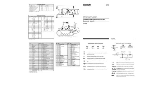
Challenger 65 Agricultural Tractor Electrical System
F-3
E - 3W8746 C - 8R3716
E-2
EE - 3W8844 C - 8R3716
F-2
FF - 3W8843 N - 3W9273
8 21
7 17
D-9
P - 8R8113 M - 3W9272
C
18
7
7YC1453-UP
C-9
Front Wiper Motor B - 8R9196
A-5
RADAR B - 8R9196 F - 3W8749
30
B
C-12 4
M - 3W9272
20
C-11
Rear Wiper Motor N - 3W9273
8 14
D-9
P - 8R8113
21
N - 3W9273
D-9
P - 8R8113
A
33
14
12
6 16
20
27 15
6
1
5
2
31
3
29 9
4
11 10
12
1
34
17
15
CHALLENGER
9 22
28
13 23
19
25
B-11
K - 4E5165
9
10
F-10
B - 8R9196
2
17
5 6
18
12
4
A
30
15
13 16
27
12 4
Vehicle Location
10
31 15
9 23
7
C 16
6
17
13
16
26 3
11
18
5
32
24
2
10 19
B-6
M - 3W9272 A - 8R7096
C-4
Front Wiper Switch B - 8R9196
Machine Connector And Component Locations
A-11
J - 3W8751 T - 3W8752
D-12
Trailer Connector
© 1990 Caterpillar All Rights Reserved
Vehicle locations are repeated for connectors located close together. * = Connector is located at the component.
Vehicle Location 1
Component Location Chart
Wire Number
Wire Color
101 102 105 109 112 114 115 116 118 119 123 124 129 130 135 146 147 148 153 154 172 174 175 176 176 177 178
RD BU BR OR PU GN PK BR GY PK WH GN BU GN BU GY PU WH WH WH GN PK PK OR YL OR GN
200 201 220 221 228
BK BK BK BK BK
C-12
304 306
WH GN
Alternator
Schematic Location C-2
Vehicle Location 19
2
Batteries
C-1
20
Sensor - Fuel Level (Perf Mon)
A-10
3
Breaker - Alternator (135A)
B-2
B
Sensor - Hitch Handle Position
B-10
3
Breaker - Main (135A)
B-2
21
Sensor - Hitch Position
B-12
A
Breaker - Running Lamp (15A)
F-7
22
Solenoid - Air Conditioner Clutch
C-3
4
Control - Draft
B-10
23
Solenoid - Hitch
B-12
A
Flasher
F-5
24
Solenoid - Start Aid
D-2
A
Fuse Block
F-6
C
Speaker - Left
E-9
A
Gauge - Coolant Temp
D-7
C
Speaker - Right
B-9
A
Gauge - Oil Press
D-7
A
Switch - Start Aid
E-8
A
Gauge - Steering Oil Temp
C-7
A
Switch - Air Conditioner Selector
B-9
A
Gauge - Transmission Oil Temp
C-7
C
Switch - Auxiliary 1
B-9
A
Horn - Alarm
D-10
C
Switch - Auxiliary 2
B-9
Component
Component Sensor - Engine Speed
Schematic Location E-2
5
Horn - Forward Warning
B-1
A
Switch - Blower
B-8
A
Lamp - Brake Accumulator
D-7
25
Switch - Brake Accumulator Press
A-7
A
Lamp - Differential Lube
D-7
26
Switch - Engine Coolant Temp (Start Aid)
D-3
A
Lamp - Implement
C-10
27
Switch - Differential Lube Press
A-8
A
Lamp - Low Fuel
D-7
B
Switch - Draft On/Off/Set
B-10
A
Lamp - Park Brake
D-7
C
Switch - Flood Lamp
C-9
A
Monitor - Performance
D-10
A
Switch - Front Wiper
C-4
6
Motor - Blower
B-3
28
Switch - Fuel Level
A-6
6
Motor - Blower
C-3
28
Switch - Fuel Level (Perf Mon)
A-5
7
Motor - Front Wiper
C-9
B
Switch - Hookup
B-11
8
Motor - Rear Wiper
C-11
9
Motor - Starting
B-2
10
Radar (Perf Mon)
A-4
30
Switch - Key
C-5
307
OR
C
Radio
D-9
B
Switch - Neutral Start
C-11
A
Relay - Forward Horn
F-5
31
Switch - Parking Brake
C-10
A
Relay - Front Wiper
B-5
31
Switch - Parking Brake (Perf Mon)
C-10
11
Relay - Main Power
A-2
B
Switch - PTO
C-10
308 310 311 320 322
YL PU WH OR GY
11
Relay - Start
A-2
A
Switch - Rear Wiper
D-8
A
Relay - Trailer Left Turn
D-5
32
Switch - Refrigerant
B-2
A
Relay - Trailer Right Turn
D-5
C
Switch - Running Lamp
C-9
A
Relay - Turn
D-5
30
Switch - Running Lamp Dimmer
C-5
A
Relay - Turn
D-6
33
Switch - Steering Oil Temp (Perf Mon)
B-12
6
Resistor - Blower Motor Speed
B-3
6
Switch - Thermostat
B-3
A
Resistor - Flasher Load
D-5
B
Switch - Throttle
B-10
403 404 414 419 428 441 447 450 456
GN YL PK YL OR OR PK YL BR
12
Sender - Coolant Temp
E-2
34
Switch - Transmission Oil Temp
A-5
13
Sender - Oil Press
F-2
30
Switch - Turn/Hazard/Horn
C-8
14
Sender - Steering Oil Temp
B-12
A
Tachometer
C-7
15
Sender - Transmission Oil Temp
A-5
C
Terminal - Customer (10A)
B-9
16
Sender - Transmission Speed (Perf Mon)
A-5
A
Terminal - Customer (30A)
F-7
17
Sensor - Coolant Temp (Perf Mon)
E-2
A
Voltmeter
D-7
18
Sensor - Engine Oil Press (Perf Mon)
E-2
Vehicle locations are repeated for components located close together. A = Components in operator compartment - Dash. B = Components in operator compartment - Console. C = Components in operator compartment - Headliner.
29
Switch - Implement Hydraulic Oil Temp (Perf Mon)
Wire Description Chart Description Power Distribution Circuits BATTERY HEAD LAMP KEY SW ALTERNATOR OUTPUT (+) TERM. MAIN POWER RELAY OUTPUT WARNING HORN (FORWARD) AUX CKT AUX CKT AUX CKT AUX CKT AUX CKT A/C AUX CKT AUX CKT AUX CKT AUX CKT AUX CKT AUX CKT 3 PT. HITCH CONT AUX CKT AUX CKT AUX CKT AUX CKT AUX CKT AUX CKT MAIN BKR MAIN BKR Ground Circuits MAIN CHASSIS OPR MON PANEL/VMIS/CMS ENG OIL PRESS. SENSOR ENG COOLANT TEMP SENSOR FUEL LEVEL SENDER Basic Machine Circuits STARTER RELAY NO.1 OUTPUT STARTER RELAY COIL TO NEUT START SW OR KEY SW KEY SW TO NEUT START SW OR VMIS SENSOR MODULE MAIN POWER RELAY COIL START AID SW TO START AID SOL START AID SOL TO TEMP SW HORN RELAY COIL TO SW WARNING HORN (FORWARD) Monitoring Circuits ALTERNATOR (R) TERM. OPR MON HYD OIL TEMP OPR MON LO FUEL OPR MON PARKING BRAKE OPR MON XMSN OIL TEMP ENG COOLANT TEMP GAGE FUEL LEVEL GAGE TACH SENDER (+) OPR MON PANEL PTO
Wire Number
Wire Color
457 458 459 460 463 464 466 469
PU PK PK BU YL GY WH GN
500 501 502 503 504 505 508 509 511 512 513 516 517 518 521 522 539 540 541 542 557 558 567 569 579 580 595
BR GN OR BR YL BU PU WH BR GN OR GN BU OR YL WH BU WH GN BU YL GN WH PK BR OR YL
602 604 605 606 607 608 610 611 614 619 620 630 635 635
WH OR YL GY PK GN OR PU PU GN WH GY BR BU
710
GN
Description Monitoring Circuits (Cont'd.) OPR MON PANEL GROUND SPEED SENDER OPR MON PANEL +V OPR MON PANEL IMPLEMENT POSITION OPR MON PANEL PROGRAM PIN SENSOR PRESENT OPR MON PANEL ENG OIL PRESS. SENSOR OPR MON PANEL STER OIL TEMP FUEL LEVEL SENDER B+ Accessory Circuits WIPER - FRONT (PARK) WIPER - FRONT (LO) WIPER - FRONT (HI) WIPER - REAR (PARK) WIPER - REAR (LO) WIPER - REAR (HI) RADIO SPEAKER - LEFT RADIO SPEAKER - LEFT (COMMON) RADIO SPEAKER - RIGHT RADIO SPEAKER - RIGHT (COMMON) A/C COMPRESSOR/REFRIGERANT PRESS. SW BLOWER MOTOR (MEDIUM) BLOWER MOTOR (LO) HAZARD FLASHER TO SW A/C SW TO REFRIGERANT SW A/C CLUTCH TO THERMOSTAT SW TURN SIGNAL INDICATOR BASIC/RIGHT TURN SIGNAL INDICATOR LEFT ACC 1 ACC 2 TRAILER CONNECTOR (LEFT TURN/HAZARD) TRAILER CONNECTOR (RIGHT TURN/HAZARD) A/C SW JUMPER A/C SW JUMPER NO.2 A/C BLOWER MOTOR NO.1 A/C BLOWER MOTOR NO.2 CH65 FRNT WPR SW(C) TO HI SPD RLY(30) & LO SPD(85) Lighting Circuits DOME LAMP STOP LAMP TURN LAMP - LEFT TURN LAMP - RIGHT FLOOD LAMP - FRONT FLOOD LAMP - REAR HEAD LAMP BASIC HEAD LAMP HI PARK/TAIL/DASH LAMP HEAD LAMP LO FLOOD LAMP - FRONT (ENG. FLOOD LAMP) FLOOD LAMP REAR (ATTACH) TURN SIGNAL COMMON PAYLOAD MON RED LAMP Control Circuits XMSN SPEED PICKUP SIGNAL
Printed in U.S.A.
Harness And Wire Electrical Schematic Symbols
Electrical Schematic Symbols And Definitions A
AA
T
Pressure Symbol
Temperature Symbol
Level Symbol
Flow Symbol
Typical representation of a Deutsch connector. The plug contains all sockets and the receptacle contains all pins.
Receptacle
Plug
1 2
1 2
1
2
Typical representation of a Sure-Seal connector. The plugand receptacle contain both pins and sockets.
Pin or Socket Number Wire, Cable, or Harness Assembly Identification
Normally open switch that will close with an increase of a specific condition (temp-press-etc.).
Component Part Number
Single Wire Connector
Normally open switch that is closed due to an applied condition, and will open again with a specific decrease in that condition.
C
A
A 325-PK-14
Pin
AA 1
325-PK-14
Wire Color
Socket
Normally closed switch that will open with an increase of a specific condition. 2
Normally closed switch that is open due to an applied condition, and will close again with a specific decrease in that condition.
9X-1123
200-BK-14
Circuit Number Identification
Wire Gauge
Electrical Schematic Symbols And Definitions
The circle indicates that the component has screw terminals and a wire can be disconnected from it.
FUSE - A component in an electrical circuit that will open the circuit if too much current flows through it.
No circle indicates that the wire cannot be disconnected from the component.
This indicates that the component has a wire connected to it that is connected to ground.
This indicates that the component does not have a wire connected to ground. It is grounded by being fastened to the machine.
REED SWITCH - A switch whose contacts are controlled by a magnet. A magnet closes the contacts of a normally open reed switch; it opens the contacts of a normally closed reed switch.
T
SENDER - A component that is used with a temperature or pressure gauge. The sender measures the temperature or pressure. Its resistance changes to give an indication to the gauge of the temperature or pressure. RELAY (Magnetic Switch) - A relay is an electrical component that is activated by electricity. It has a coil that makes an electromagnet when current flows through it. The electromagnet can open or close the switch part of the relay. CIRCUIT BREAKER (C/B) - A component in an electrical circuit that will open the circuit if too much current flows through it. This does not destroy the circuit breaker and it can be reset to become part of the circuit again. SOLENOID - A solenoid is an electrical component that is activated by electricity. It has a coil that makes an electromagnet when current flows through it. The electromagnet can open or close a valve or move a piece of metal that can do work. MAGNETIC LATCH SOLENOID - A magnetic latch solenoid is an electrical component that is activated by electricity and held latch by a permanent magnet. It has two coils (latch and unlatch) that make electromagnet when current flows through them. It also has an internal switch that places the latch coil circuit open at the time the coil latches.