Component Location Schematic Location
Machine Location
Alarm - Action
A-4
A
Alarm - Backup
D-9
1
Alternator
B-2
Battery
Wire Number
Wire Color
101
RD
102 105
Wire Description Wire Number
Wire Color
Bat (+)
509
WH
Radio Speaker - Left (Common)
BU
Hd Lmp
511
BR
Radio Speaker - Right
BR
Key Sw
512
GN
Radio Speaker - Right (Common)
108
BU
Aux Ckt
513
OR
A/C Compressor/Refrigerant Press. Sw
Description
Machine Location
Sender - Coolant Temp.
D-2
22
Sender - Fuel Level
D-9
17
2
Sender - Powertrain Oil
E-2
19
F-9
1
Solenoid - A/C Clutch
B-2
22
109
OR
Alt Output (+) Term.
515
GY
Blower Motor (Hi)
Breaker - Alternator
E-8
3
Solenoid - Engine Shutdown
C-2
A
112
PU
Main Power Rly Output
516
GN
Blower Motor (Medium)
Breaker - Aux
E-8
3
Solenoid - Start Aid
F-2
A
113
OR
Opr Mon Panel B (+) Switched
517
BU
Blower Motor (Lo)
Breaker - Blower
F-8
3
Starter
C-2
26
114
GN
Warning Horn (Forward)
521
YL
A/C Sw to Refrigerant Sw
Cigar Lighter
A-5
C
Switch - Air Heater Coolant
D-2
16
116
BR
Aux Ckt
522
WH
A/C Clutch to Thermostat Sw
Motor - Condenser
B-9
7
Switch - Air Inlet Heater
C-6
A
124
GN
A/C
523
BR
Wiper - Left (Park)
Converter - 24V to 12V
D-7
3
Switcch - Backup Alarm
E-5
B
129
BU
Aux Ckt
524
BU
Wiper - Left (Lo)
Fuses
E-8
3
Switch - Blower
B-6
A
140
BU
Aux Ckt
525
GY
Wiper - Left (Hi)
Aux Ckt
526
YL
Wiper - Right (Park)
C-4
Switch - Coolant Temp.
D-2
22
BR
Gauge - Coolant Temp.
A
158 160
PU
Aux Ckt
524
GN
Wiper - Right (Lo)
Gauge - Fuel Level
B-4
A
Switch - Disconnect
F-9
1
176
OR
Aux Ckt
528
PK
Wiper - Right (Hi)
Gauge - Powertrain Oil Temp.
C-4
A
Switch - Engine Oil
E-2
24
197
GN
Aux Ckt
529
WH
Washer Left
Engine Intake Air Heater
B-2
16
Switch - Ether Coolant
D-2
22
198
PK
Aux Ckt
530
OR
Washer Right
Horn - Forward
F-1
5
Switch - Forward Horn
B-5
C
199
OR
Aux Ckt
592
BU
DC/DC Converter Power Output
Lamp - Dome
A-6
30
Switch - Front Wiper
A-7
13
593
GN
Condenser Fan Relay to Motors
Meter - Service
B-4
A
Switch - Fuel Pressure
E-2
18
A513
PK
DC/DC Converter Memory Output
Motor - Blower
A-3
6
Switch - Hydraulic Oil
A-7
18
Motor - Blower
B-3
6
Switch - Key Start
C-6
A
BR
Dash Lamp Basic
Motr - Front Wiper
E-4
8
Switch - Lamp
D-6
A
Motor - Left Wiper
E-5
9
Switch - Left Wiper
A-7
13
Motor - Rear Wiper
C-8
10
Switch - Neutral Start
D-5
Motor - Right Wiper
B-6
11
Switch - Operater Monitor
Motor - Washer(Front, Rear, Left, & Right)
D-8
3
Radio
C-3
Relay - Condensor
Component
Component
Accessory Circuits (Continued)
Power Distribution Circuits
Ground Circuits 200
BK
Main Chassis
201
BK
Opr Mon Panel CMS
202
BK
XMSN Ctrl
600
203
BK
Chassis Diagnostic
608
GN
Flood Lamp - Rear
207
BK
Starter Diaostic
610
OR
Head Lamp Basic
270
BK
CMS Ident Code 0
663
GY
Gage Lamps - Smart EMS
B
271
BK
CMS Ident Code 1
A-5
A
272
BK
CMS Ident Code 2
709
OR
Sensor Power Supply
Switch - Power Train Filter
A-8
23
273
BK
CMS Ident Code 3
751
GN
XMSN Shift Sol No.1 or 3
12
Switch - Power Train Filter Bypass
A-8
19
274
BK
CMS Ident Code 4
752
YL
XMSN Shift Sol No.2
B-9
7
Switch - Powertrain Oil
E-2
19
275
BK
CMS Ident Code 5
754
BU
XMSN Shift Sol No.3 or 1
Realay - Main
F-8
3
Switch - Rear Wiper
B-8
13
276
BK
XMSN Ctr Ident Code 0
755
OR
XMSN Shift Sol No 4 or 5
Relay - Start
F-8
3
Switch - Refrigerant
C-1
22
277
BK
XMSN Ctr Ident Code 1
E707
GN
Display +V
Resistor - Blower
A-3
6
Switch - Right Wiper
B-8
13
278
BK
XMSN Ctr Ident Code 2
E708
PK
Display Clock
XMSN Ctr Ident Code 3
E735
PU
Smart EMS Tack/Serv Mtr/Odometer Select
B-3
Switch - Start Aid
C-6
A
BK
Resistor - Blower
6
279 280
BK
XMSN Ctr Ident Code 4
F780
PK
Parking Brake Sw
C-2
26
Thermostat
B-3
A
290
BK
CMS Service
F781
BR
Downshift Sw (N.O.)
291
BK
CMS Clear
F782
OR
Reverse Sw (N.O.)
F783
GN
Upshift Sw (N.C.)
Resistor - Starter
Machine locations are repeated for components located close together.
Lighting Circuits
B = Located inside of right console. C = Located inside of left console. D = Located around relay panel. E = Located around hydraulic oil tank. F = Located around pilot manifold. G =Located under platform.
Connector Location¹
Title
Form Number
301
BU
Starter No. 1 Sol.
F784
YL
Downshift Sw(N.C.)
302
OR
Starter No. 1 Resistor to Diagnostic
F785
WH
Upshift Sw (N.O.)
304
WH
Starter Rly No. 1 Output
F786
GY
Reverse Sw (N.C.)
306
GN
Starter Rly Coil to Neut Start SW or Key SW
F788
PU
Left Steer Clutch
307
OR
Key SW to Neut Start SW
F789
YL
Right Steer Clutch
308
YL
Main Power Rly Coil
F790
BR
Service Brake Pedal
310
PU
Start Aid SW to Start Aid Sol.
F791
BU
Right Brake Solenoid
311
WH
Opr Mon Master
F792
WH
Left Brake Solenoid
PK
EPTC II - Park Brake Sol
Schematic Location
Machine Location
321
BR
Opr Mon Parking Brake
G730
322
GY
Eng Coolant Temp Gauge
G731
GY
EPTC II - Secondary Service Brake Sol
CONN 1
D-12
28
326
PU
Hyd System Temp Gauge
828
WH
Hydrst Left Ster Pedal Sensor
CONN 2
A-11
14
334
BU
Power Train Temp Gauge
830
OR
Hydrst Right Ster Pedal Sensor
CONN 3
C-11
3
335
BR
Fuel Level Gauge
851
WH
Hydrst Speed and Direction Sensor
CONN 4
D-11
3
337
WH
Display Data
892
BR
Port/CAT Data Link (-)
373
GN
Display Load
893
GN
Port/CAT Data Link (+)
F842
BU
AIH Post Heat
Connector Number
Related Service Manuals Alternator 132-2156
SENR4757
Starting And Charging Systems
SENR2945
CONN 5
A-10
3
Electronic Monitoring System
SENR2945
CONN 6
B-10
18
Starter - 108-8558
SENR3559
CONN 7
F-10
3
CONN 8
A-9
A
CONN 9
B-9
A
CONN 10
D-9
19
Monitoring Circuits
CONN 11 F-9 19 ¹ The connectors shown in this chart are for harness to harness connectors with a minimum of four contacts and other special connectors. Connectors that join a harness to a component are generally located at or near the component. See the Component Location Chart.
3
403
GN
Alternator ( R) Term.
F843
YL
Inching Pedal
404
YL
Wiper - Front (Low)
F846
PU
ECB LED Driver
405
GY
Wiper - Front (HI)
F847
YL
ECB Sw IP1
406
PU
Wiper - Rear (Park)
F848
OR
ECB Sw IP2
410
WH
Wiper - Rear (Low)
F849
WH
ECB Sw IP3
411
PK
Wiper - Rear (HI)
F849
WH
ECB Sw IP3
413
BR
Washer - Front
F850
PK
ECB Sw IP4
415
GN
Washer - Rear
G848
No
Auto Indicator
419
YL
Radio Speaker - Left
900
PU
XMSN Shift Sol No.5 or 4
424
GY
Radio Speaker - Left (Commom)
973
BR
CST Autoshift - Auto/Manual Sw 2
426
BR
Radio Speaker - Right
975
WH
CST Autoshift - Sol Return
441
OR
Radio Speaker - Right (Common)
977
YL
CST Autoshift - Auto/Manual Sw 1
442
GY
A/C Compressor/Refrigerant Pressure SW
E900
WH
ECM Trans Output Spd +
443
YL
Blower Motor (HI)
E901
GN
ECM Trans Output Spd -
447
PK
Blower Motor (Medium)
E902
PU
ECM Trans Interm Spd +
450
YL
Blower Motor (Low)
E903
YL
ECM Trans Interm Spd -
C413
YL
A/C SW To Refrigerant SW
E903
YL
ECM Trans Interm Spd -
C414
BU
A/C Clutch To Thermostat SW
E904
BR
ECM Trans Interm Spd Q+
E904
BR
ECM Trans Interm Spd Q+
500
BR
Wiper - Front (Park)
E905
BU
ECM Trans Interm Spd Q-
501
GN
Wiper - Front (Lo)
E906
OR
ECM Trans Output Spd Q+
502
OR
Wiper - Front (Hi)
E907
GY
ECM Trans Output Spd Q-
503
BR
Wiper - Rear (Park)
E908
BR
ECM Trans Intput Spd +
504
YL
Wiper - Rear (Lo)
E909
WH
ECM Trans Intput Spd -
505
BU
Wiper - Rear (Hi)
G939
PK
ECM Switch Return
506
PU
Washer - Front
K977
PK
ECM Trans Oil Temp Sensor
507
WH
Washer - Rear
K978
BU
ECM Pump Sol
508
PU
Radio Speaker - Left
K997
BU
+V Sensor, SEMS
Accesory Circuits B
9
24
19
2 5
8
12
23
7
6
A
17
22
4BR1-UP
C
A
Pressure Symbol
Temperature Symbol
Level Symbol
Flow Symbol
13
B
12
30
10
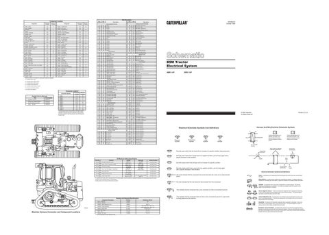
Typical representation of a Deutsch connector. The plug contains all sockets and the receptacle contains all pins.
2
8
A
C
Actuate
3E-6449
Air Heater & Start Aid Coolant
3E-6451
Engine Coolant Temperature (EMS)
3E-6454
Fuel Pressure (EMS)
3E-9350
Power Train Filter Bypass Temperature
9X-7781
Power Train Filter
114-5333
Refrigerant Pressure (AC)
130-3015
Coolant Temp Switch
38 ± 3° C (100 ± 5° F) 107.0 ± 3.0° C (224.6 ± 6.0° F) 70 kPa MAX (10 psi MAX) 52 ± 3°C (125.6 ± 5.4° F) 210 ± 70 kPa (30 ± 10 psi) 275 to 1750 kPa ¹ (40 to 255 psi) 110 ± 5° C to Open (230.0° F ± 8° C)
Wire, Cable, or Harness Assembly Identification
C
Normally open switch that is closed due to an applied condition, and will open again with a specific decrease in that condition. Deactuate
Normally Closed
325-PK-14
Pin
Normally closed switch that will open with an increase of a specific condition.
Normally Closed Normally Closed
-
Normally Open
-
Normally Open²
-
96° C from Open to Closed (204.8° F)
Normally Closed
The circle indicates that the component has screw terminals and a wire can be disconnected from it.
This indicates that the component has a wire connected to it that is connected to ground.
5
Wire Gauge
REED SWITCH - A switch whose contacts are controlled by a magnet. A magnet closes the contacts of a normally open reed switch; it opens the contacts of a normally closed reed switch.
T
22 24
200-BK-14
FUSE - A component in an electrical circuit that will open the circuit if too much current flows through it.
2
23
Wire Color
Socket
Electrical Schematic Symbols And Definitions
3
16
9X-1123 325-PK-14
Circuit Number Identification
Normally closed switch that is open due to an applied condition, and will close again with a specific decrease in that condition.
No circle indicates that the wire cannot be disconnected from the component.
1
11
AA 1
2
Normally Closed
² Contact postion at the contacts of the harness connector.
9
A
A
Contact Position
27° C MIN. (80.6° F) 93.0° C MIN. (199.0°F MIN.) 40 ± 20 kPa (6.0 ± 3.0 psi) 43° C MIN. (109.4° F MIN.) -
Component Part Number
Single Wire Connector
¹ A hysteresis band exists: with increasing pressure the closed condition can be maintained up to 2800 kPa (405 psi), with decreasing pressure the closed condition can be maintained down to 170 kPa (25psi).
6
Typical representation of a Sure-Seal connector. The plugand receptacle contain both pins and sockets.
Pin or Socket Number
Normally open switch that will close with an increase of a specific condition (temp-press-etc.).
Function
1 2
1 2
Receptacle
Plug
T
30
Part No.
7
AA 1
Off Machine Switch Specification
17
Harness And Wire Electrical Schematic Symbols
Electrical Schematic Symbols And Definitions
26
11
13
Printed in U.S.A.
© 1996 Caterpillar All Rights Reserved
1
18
3DR1-UP
16
10
18
D5M Tractor Electrical System
Control Circuits
Basic Machine Circuits
A = Located inside of cab.
SENR9472 October 1996
Description
Schematic Location
SENDER - A component that is used with a temperature or pressure gauge. The sender measures the temperature or pressure. Its resistance changes to give an indication to the gauge of the temperature or pressure. RELAY (Magnetic Switch) - A relay is an electrical component that is activated by electricity. It has a coil that makes an electromagnet when current flows through it. The electromagnet can open or close the switch part of the relay.
26
Component Description
D74334
Machine Harness Connector and Component Locations
Resistor and Solenoid Specifications
This indicates that the component does not have a wire connected to ground. It is grounded by being fastened to the machine.
Part No.
Resistance (Ohms)¹
Relay - Condensor
3E-5239
360
Sloenoid - Start Aid
3E-6332
6
Resistor - Starter/Diagnostic Conn.
3E7842
Solenoid - Engine Start/Stop
8C-3663
Resistor - Blower Motor
9G-1950
Relay - Main Power
101-7740
53. ± 5.3
Relay - Start
125-1302
27.5 ± 2.8
Solenoid - A/C Clutch
134-3999
17.6 ± 0.6
¹ At room temperature unless otherwise noted.
150± 7.5 Start (Latch) Coil - 1.55 ± 0.15 Stop (Unlatch) Coil - 10.3 ± 1.03 Overall 2.0 ± 0.1
CIRCUIT BREAKER (C/B) - A component in an electrical circuit that will open the circuit if too much current flows through it. This does not destroy the circuit breaker and it can be reset to become part of the circuit again. SOLENOID - A solenoid is an electrical component that is activated by electricity. It has a coil that makes an electromagnet when current flows through it. The electromagnet can open or close a valve or move a piece of metal that can do work. MAGNETIC LATCH SOLENOID - A magnetic latch solenoid is an electrical component that is activated by electricity and held latch by a permanent magnet. It has two coils (latch and unlatch) that make electromagnet when current flows through them. It also has an internal switch that places the latch coil circuit open at the time the coil latches.