KENR1313-01 October 1992
7
8 4
Component
4 14
12
Alarm — Backup
9
17
1
16
1
A
3
13
2
B
6
5
3
15
2
10
11
A
3
B
Schematic Location SH2-E8
Component Location Machine Location 1
Solenoid — Fuel Shutoff
Schematic Location 13
Machine Location 13
Alternator
SH2-B8
2
Solenoid — Vib Control Valve
12
12
Battery
SH2-D6
3
Solenoid — Vib Control Valve
12
12
Battery
SH2-D7
3
Solenoids — Vib Select Valve
14
14
Breaker — Main
SH2-A8
4
Switch — Auto-Vib/Speed
A
A
Flasher
SH1 -C4
B
Switch — Automatic/Manual
B
B
Fuse Block
SH1-E4
A
Switch — Backup Alarm Pressure
B
B
Horn — Alert Operator
SH1-F6
5
Switch — Brake Pressure
14
14
Horn — Forward
SH2-E3
6
Switch - Brake
B
B
Instrument Cluster
SH1-E2
A
Switch — Drum Offset
B
B
Instrument Cluster
SH1-E2
A
Switch - Drum Select
B
B
Lamp — Alternator Indicator
SH1-D3
A
Switch — Engine Coolant Temp
2
2
Meter — Service Hour
SH1-E3
A
Switch — Engine Oil Press
15
15
Motor — Front Water Pump
SH2-D2
7
Switch — Engine Oil Press (Ser Meter)
15
15
Motor — Rear Water Pump
SH2-D8
8
Switch — Filter Press (Fuel)
16
16
Motor — Starter
SH2-D8
9
Switch — Forward Horn
B
B
Recorder Module
SH1-B7
A
Switch — Hydraulic Oil Temp
17
17
Relay — Gage
SH1-F3
A
Switch — Ignition
A
A
Relay — Main Power
SH2-A8
4
Switch - Light
B
B
Relay — Start
SH2-B8
4
Switch — Neutral Start
B
B
Relay — Vibratory Tach
SH1-A2
B
Switch - Turn
B
B
Relay — Water Pump
SH1-C4
B
Switch — Vibration Cutout
B
B
Sensor — Auto-Vib/Speed
SH2-D6
10
Switch — Water Spray
A
A
Sensor Front Vibratory
SH2-E4
11
Switches — Vibration Pressure
B
B
Sensor — Rear Vibratory
SH2-F6
10
Tachometer — Ground Speed (FPM)
A
A
Sensor — Speed (Recorder)
SH2-E6
10
Tachometer — Vibration (VPM)
A
A
Timer — Water Spray
A
A
SH2-A6 Solenoid — Brake 12 Machine locations are repeated for components located close together. A = Components located in dash area. B = Components located in right console.
17
Component
CB-434 Vibratory Compactor Electrical System 3TF1-217
5 3
2 2
1
4
4 15
10
16
12
9 1
14 13
8
7
11
6
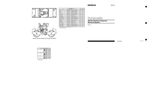
Machine Harness Connector And Component Locations ©1992 Caterpillar All Rights Reserved
Harness Connector Location Chart Connectors
Machine Location 1 1
10 Contacts
1 A A
7 Contacts
* 2
6 Contacts
2 2 2
5 Contacts
B 3
* 4 Contacts
4 4
Harness And/Or Components
A—6R1099 E — 6R1 383 A—6R1099 E — 6R1 383 A—6R1099 E — 6R1383 A — 6R1099 K—6R1990 A — 6R1099 L—7R5513 A-6R1 099/B-1 G61 46 Recorder C — 6R0078 E—6R1383 E — 6R1383 H — 6R0046 E — 6R1383 R — 7R4624 E — 6R1383 S—871444 A — 6R1099 Neutral Start Sw A — 6R1099 J—6R1989 A — 6R1099 Horn B—1G6146 F — 1G6145 E—6R1383 Vib Valve Solenoid
Machine locations are repeated for connectors located close together. * = Connector is located at the component. A = Connectors located in dash area. B = Connectors located in right console.
Schematic Location SH1-E8 SH2-E1 SH1-D8 SH2-E1 SH1-C8 SH2-C1 SH1-D5 SH1-E5 SH1 -A5 SH2-F5 SH2-D5 SH2-D5 SH2-C5 SH1-C3 SH1-05 SH1-F6 SH1-C8 SH2-C1 SH2-B4
Printed in U.S.A.