Part No.
Function
Actuate
Deactuate
Contact Position
Wire Number
Wire Color
Wire Number
Description
Wire Description Color Monitoring Circuits Continued
52±3°C
43°C MIN
Normally
(125.6±6°F)
(109.4°F MIN)
Closed
101
RD
Bat (+)
82.22±2.78°C
73.89°C MIN
Normally
104
RD
Alt Breaker
(180±5°F)
(165°F MIN)
Open
107
RD
Eng Shut - Down Fire Suppr
¹A hysteresis band exist: with increasing pressure the closed condition can be maintained up to 2800kPA (405 psi),
109
RD
Alt Output (+) Term.
500
BR
Wiper - Front (Park)
with decreasing pressure the closed condition can be maintained down to 170 kPa (25 psi).
112
RD
Main Power Rly Output
501
GN
Wiper - Front (Low)
²Contact position at the contacts of the harness connector.
115
RD
Lamp/Wiper
506
PU
Washer - Front
120
YL
Radio
508
PU
Radio Speaker - Left
121
YL
Back Alarm To Lamp
509
WH
Radio Speaker - Left (Commom)
124
GN
A/C
511
BR
Radio Speaker - Right
142
BU
Aux Ckt
512
GN
Radio Speaker - Right (Common)
151
GN
Hyd Lock Sol
513
OR
A/C Compressor/Refrigerant Pressure SW
190
BK
Eng Gov/Monitor
515
GY
Blower Motor (HI)
517
BU
Blower Motor (Low)
3E9350
Oil Cooler Temp Switch
7N7848
Hyd Oil Temp Switch
KENR2918 January 2000
Wire Description
Off Machine Switch Specification
Power Circuits
PK GN
Fuel Level guage Hyd Shutoff Valve
Accesory Circuits
Ground Circuits 200
BK
Main Chassis
519
PK
Thermostat To Refrigerant Press. SW
201
BK
Operator Monitor Return
535
BU
SW To Wiper SW
A588
GN
Safety Sol Relay To Sol+
Basic Machine Circuits
Related Electrical Service Manuals
447 C400
Lighting Circuits
306
GN
Starter Relay Coil To Neut Start SW
307
OR
Key SW To Neutral Start SW
612
GY
Backup Lamp
309
GY
Alternator Regulator Term.
616
BU
Bucket Flood Lamp/Boom Flood Lamp
310
PU
Start Aid SW To Start Aid Sol
315
GN
Start Aid Breaker To Start Aid Relay
762
YL
Bucket Positioner Sol SW
320
OR
Horn Relay Coil To SW
763
BU
Torque Converter SW
321
BR
Backup Alarm Lamp Travel Alarm
799
WH
Sensor Power
322
GY
Warning Horn (Forward)
B786
BU
Low Idle SW
323
WH
Fuel Pump Power
D746
PK
Alt Signal To Anti-Start Relay
327
PK
Shutdown Solenoid
E771
OR
Low Torque Mode Sol
330
YL
Neutral Start Relay Coil
817
WH
Back-Up Alarm Relay
877
YL
Glow Plug Magnetic SW To Glow Plug
D813
OR
Low Idle SW HEDC
Control Circuits
Title
Form Number
332
BU
Shutdown SW To Shutdown Ctrl
Alternator 163-3362
SENR5841
364
BU
Engine Shutdown SW - Ctrl
Monitoring Circuits
D814
GY
Implement Press SW
403
GN
Alternator (R) Term.
D815
PU
Low Idle Indicator
405
GY
Opr Mon Oil Press. (Low Setting)
D816
WH
Eng/Pump Cont Sol
406
PU
Opr Mon Coolant Temp
B965
GY
Level Finish Sol
441
OR
Eng Coolant Temp Guage
K906
GN
Swing Brake Sol - Signal
442
GY
Hyd System Temp Guage
K915
GN
Fine Swing SW - E/P Controller
CB-214D, CB-224D, and CB-225D Vibratory Compactor Electrical System CB-214D: 1TZ1-UP
CB-224D: 8RZ1-UP
CB-225D: 9FZ1-UP
©2000 Caterpillar All Rights Reserved
Printed in U.S.A.
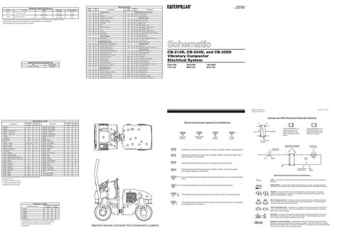
Harness And Wire Electrical Schematic Symbols Component Location Schematic Location
Component
Machine Location
Comonent
Schematic Location
Machine Location
Alternator
D-12
8
Solenoid - Drum Select
A-10
19
Battery
F-11
10
Solenoid - Flow Divider
B-9
25
Breaker - Alternator Cicuit
E-7
2
Solenoid - Fuel Shutoff
A-11
20
Breaker - Light Circuit
E-7
2
Solenoid - Interlock
A-11
18
Control - Handle VIB
A-5
15
Solenoid - Neutral/Brake
A-10
21
Flasher
F-3
3
Solenoid - VIB On/Off
A-10
19
Fuse Block
F-4/5
3
Starter
F-10
9
Glow Plugs
B-12
20
Switch - Brake
B-1
1
Gound
B-11
19
Switch - Cool Temp
A-11
20
Ground - Chassis
E-12/F-12
23/11
Switch - Drum Select
E-1
1
Ground - Engine
F-12
11
Switch - Emulsion
F-1
1
Ground - Frame
C-9
24
Switch - Flow Divider
A-8
26
Ground - Front/Rear
E-12
23
Switch - Hazard
D-1
1
Hour Meter
E-7
2
Switch - Horn
C-1
1
Lights - Warning
C-1
1
Switch - Hyd Oil Temp
B-8
22
Pump - Emulsion Spray
A-7
5
Switch - Key
B-1
1
Pump - Water Spay (225 Only)
A-7
4
Switch - Light
F-2
1
Pump - Water Spay (214, 224 Only)
A-7
6
Switch - Neutral
A-5
14
Relay - Brake 1
A-3
14
Switch - Neutral Backup
A-12
18
Relay - Brake 2
A-3
14
Switch - Oil Pressure
A-11
20
Relay - Fan Motor
A-4
14
Switch - Seat
A-6
16
Relay - Interlock 1
A-3
14
Switch - Start Aid
D-1
1
Relay - Interlock 2
A-2/E-7
14
Switch - Turn Signal
E-1
1
Relay - Main Power
E-8
2
Switch - Water Spray
E-1
1
Relay - Spray
A-4
14
Timer
F-3
3
Relay - Starter
E-8
2
Turn Signal Indicator
D-1
1
Relay - Starter
A-2/E-7
14/2
VIB Lamp Indicator
D-1
1
Electrical Schematic Symbols And Definitions
A
AA
4 25
26
19 21
18
23
Pressure Symbol
9
20
8
6
2
Level Symbol
Typical representation of a Sure-Seal connector. The plugand receptacle contain both pins and sockets.
Flow Symbol Pin or Socket Number
10
2
11
24
15
Temperature Symbol
17
3 14 5
Receptacle
T
1 16
Typical representation of a Deutsch connector. The plug contains all sockets and the receptacle contains all pins.
22
Plug
1 2
1 2
1
Wire, Cable, or Harness Assembly Identification
Component Part Number
Single Wire Connector
Normally open switch that will close with an increase of a specific condition (temp-press-etc.). C
A
A 325-PK-14
Normally open switch that is closed due to an applied condition, and will open again with a specific decrease in that condition. Pin
Normally closed switch that will open with an increase of a specific condition.
AA 1
9X-1123 325-PK-14
Wire Color
Socket
2
200-BK-14
Circuit Number Identification
Normally closed switch that is open due to an applied condition, and will close again with a specific decrease in that condition.
Wire Gauge
Electrical Schematic Symbols And Definitions The circle indicates that the component has screw terminals and a wire can be disconnected from it.
Machine locations are repeated for components located close together. A Located in the cab. B Located in the lefthand console.
FUSE - A component in an electrical circuit that will open the circuit if too much current flows through it.
15
C Located in the righthand console.
1
D Located on or near relay panel.
REED SWITCH - A switch whose contacts are controlled by a magnet. A magnet closes the contacts of a normally open reed switch; it opens the contacts of a normally closed reed switch.
No circle indicates that the wire cannot be disconnected from the component. 3 16 19 2
14 22
20
18 5
Connector Location
CONN 1
Schematic Location D-9
Machine Location 25
CONN 2
C-9
25
CONN 3
E-5
24
CONN 4
E-5
24
CONN 5
D-5
24
CONN 6
C-5
24
Connector Number
21
6 4
T
10
8
26
This indicates that the component has a wire connected to it that is connected to ground.
17
SENDER - A component that is used with a temperature or pressure gauge. The sender measures the temperature or pressure. Its resistance changes to give an indication to the gauge of the temperature or pressure.
9
This indicates that the component does not have a wire connected to ground. It is grounded by being fastened to the machine.
RELAY (Magnetic Switch) - A relay is an electrical component that is activated by electricity. It has a coil that makes an electromagnet when current flows through it. The electromagnet can open or close the switch part of the relay.
24 11 25
23
CIRCUIT BREAKER (C/B) - A component in an electrical circuit that will open the circuit if too much current flows through it. This does not destroy the circuit breaker and it can be reset to become part of the circuit again. SOLENOID - A solenoid is an electrical component that is activated by electricity. It has a coil that makes an electromagnet when current flows through it. The electromagnet can open or close a valve or move a piece of metal that can do work.
The connectors shown in this chart are for harness connectors. Connectors that join a harness to a component are generally located at or near the component. See the Component Location Chart.
Machine Harness Connector And Component Locations
MAGNETIC LATCH SOLENOID - A magnetic latch solenoid is an electrical component that is activated by electricity and held latch by a permanent magnet. It has two coils (latch and unlatch) that make electromagnet when current flows through them. It also has an internal switch that places the latch coil circuit open at the time the coil latches.