Wire Description
Control - Powertrain
E-9
Transmission Shift Solenoid Number 2
Control - Stick
F-5
BU
Transmission Shift Solenoid Number 3 Or 1
Flasher
F-2
OR
Transmission Shift Solenoid Number 4 Or 5
Lamp - Quickshift Indicator
892
BR
893
GN
Converter
900
PU
Transmission Shift Solenoid Number 5 Or 4
YL
Backup Alarm To Lamp
939
PK
Between Connector 4 And 5
123
WH
Temperature Gages and Lockup
975
WH
CST Autoshift-Solenoid Return
124
GN
A/C
6706
WH
Cruise Control On/Off
127
OR
Flood Lamp
6709
BU
Set/Accelerate
128
PK
Kickouts
A273
BK
MAC-14 Transmission Control B -
129
BU
Cigar Lighter
C491
PU
Park Brake Pressure
130
GN
Heater Blower Motor
C922
PU
Service Brake Switch To Powertrain Control
199
OR
Powertrain Control Battery +
C985
BU
Volts +8
Ground Circuits
E705
BU
Impeller Clutch Pressure
Wire Color
102
RD
Battery +
108
BU
Throttle Lock
113
OR
Opr Mon Panel VMIS B+ Switched
118
GY
Front Wiper
119
PK
Rear Wiper
120
YL
121
Description
Wire Number
Wire Color
752
YL
754 755
Power Circuits
Solenoid - Second Gear Clutch #4
A-10
Machine Location 47
C
Solenoid - Third Clutch #3
B-10
47
B
Solenoid - Throttle Lock
B-4
46
C-1
B
Suppressor - Arc
B-5
A
VMIS Start Mod Right (-) Port/Cat Data Link (-)
Lamp - Reducing Rimpull indicator
C-1
B
Switch - Brake Accum Pressure
D-10
10
VMIS Start Mod Right (+) Port/Cat Data Link (+)
LED - Actual Gear
B-10
B
Switch - Hazard
E-1
B
Relay - Backup Alarm
A-8
C
Switch - Key Start
C-6
A
Relay - Throttle Lock
A-5
A
Switch - Park Brake Pressure
D-10
10
Sensor - Impeller Clutch Pressure
E-10
9
Switch - Quickshift
E-1
B
Sensor - LH Pedal
E-4
A
Switch - Reduced Max Rimpull
A-6
A
Sensor - Torque Converter Oil Temp
E-10
9
Switch - Reducing Rimpull Selector
C-1
B
Sensor - Torque Converter Speed
F-10
9
Switch - RH Service Brake Pedal
C-4
A
Solenoid - Air Start
E-10
8
Switch - Steering Trans Lock
F-5
C
Solenoid - First Gear Clutch #5
A-10
47
Switch - Stop Lamp
D-10
10
Solenoid - Forward Clutch #2
B-10
47
Switch - Throttle Lock
B-4
A
Solenoid - Impeller Clutch
F-10
9
Switch - Torque Converter Lockup
D-1
B
Solenoid - Lockup Clutch
F-10
9
Switch - Turn signal
F-1
B
Solenoid - Reverse Clutch #1
B-10
47
200
BK
Main Chassis
E988
PU
WL Rimpull Switch Input 1
201
BK
Operator Monitor Panel
E989
WH
WL Rimpull Switch Input 2
202
BK
Xmsn Cont
F741
WH
Impeller Clutch Resume Switch
240
BK
Engine Speed Con
G746
WH
Transmission Control Torque Limit
241
BK
Operator Monitor Time Delay Pin 3
G747
OR
Transmission Control Lockup Prop Solenoid
G747
WH
Lockup Clutch Solenoid
Basic Machine Circuits
Component
Description Control Circuits (Continued)
306
GN
Starter Relay Coil To Neut Start Sw or Key Sw
G748
PU
Transmission Control Steer Console Switch 1
307
OR
Key Start Switch To Battery +
G749
YL
Transmission Control Steer Console Switch 2
321
BR
Backup Alarm Lamp Travel Alarm
G750
BU
Transmission Control Forward Switch to Ground
331
OR
Backup Alarm Relay Coil
G753
YL
Park Brake Pressure Switch To Powertrain Ctrl
Monitoring Circuits
G755
GY
Transmission Control Reverse Switch To Gnd
Schematic Location
Component Location Machine Location C
Wire Number
Schematic Location
Component
Connector Location
Schematic Location
Connector Number CONN 1
47
CONN 2
9
CONN 3
8
CONN 4
9
CONN 5
A
CONN 6
A
407
PK
Operator Mon Converter/Retarder Oil Temp
G758
PU
Quickshift Switch (N.C.) Lever Steer
432
PK
Operator Monitor Brake Press. (Oil)
G759
WH
Quickshift Switch (N.O.) Lever Steer
452
PU
Torque Converter
G760
WH
Transmission Cont Speed 2 Switch To Ground
467
WH
System Fault (Xmsn)
G761
YL
Transmission Cont Speed 3 Switch To Ground
CONN 7
A
G762
BR
Transmission Cont Speed 4 Switch To Ground
CONN 8
B
CONN 9
B
CONN 10
6
BR
Hazard Indicator Lighting Circuits
G763
PU
G765
GN
Transmission Cont Lever Enable
G768
GN
Transmission Cont Speed 1 Switch To Ground
600
BR
Dash Lamp Basic
G794
OR
Transmission Quickshift Indicator Lamp
604
OR
Stop Lamp
G939
PK
MAC-14 Switch Return
605
YL
Turn Lamp Left
H724
YL
XMSN Cont Impeller Clutch Prop Sol (Was D724)
606
GY
Turn Lamp Right
H735
GY
Driver Signal 1
679
GY
Impeller Clutch Memory Indicator
H736
BU
Driver Signal 2
Control Circuits
H737
YL
Driver Signal 3
709
OR
Sensor Power Supply
P911
PU
Rimpull Switch Input 3
710
GN
Xmsn Speed Pickup Signal
P912
BU
Rimpull Switch Input 4
751
GN
Transmission Shift Solenoid Number 1 or 3
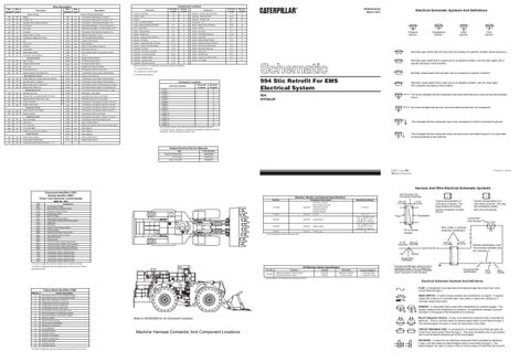
994 Stic Retrofit For EMS Electrical System
Machine Location
Park Brake - Lever Steer
WH
Normally open switch that is closed due to an applied condition, and will open again with a specific decrease in that condition.
Normally closed switch that will open with an increase of a specific condition.
YL
538
Flow Symbol
Level Symbol
Normally open switch that will close with an increase of a specific condition (temp-press-etc.).
B = Located on or near the Dash.
G756
536
Temperature Symbol
Pressure Symbol
C =Located under platform.
Alternator (R) Term.
Transmission Cont Neutral Switch to Ground
T
A = Located inside of cab.
GN
Hazard Switch to turn Switch
Electrical Schematic Symbols And Definitions
RENR6040-00 March 2001
Machine locations are repeated for components located close together.
403
Accessory Circuits
CJLTERPILLAR®
CONN 11
6
CONN 12
B
CONN 13
B
CONN 14
B
Normally closed switch that is open due to an applied condition, and will close again with a specific decrease in that condition.
w
994: 9YF28-UP
The circle indicates that the component has screw terminals and a wire can be disconnected from it.
No circle indicates that the wire cannot be disconnected from the component.
~
CONN 15 B The connectors shown in this chart are for harness to harness connectors. Connectors that join a harness to a component are generally located at or near the component. See the Component Location Chart.
~
This indicates that the component has a wire connected to it that is connected to ground.
i¥11-
This indicates that the component does not have a wire connected to ground. It is grounded by being fastened to the machine.
Related Electrical Service Manuals Title
Form Number
Electrical Schematic:
SENR5929
STIC Control:
RENR3306
Power Train ECM:
RENR2522
©2001 Caterpillar Ail Rights Reserved
~'rinled in U.S.A.
Harness And Wire Electrical Schematic Symbols
CID
Part No.
Resistor, Sender and Solenoid Specifications Component Description
147-5399
Solenoid:
First Gear Clutch #5 Second Gear Cl;utch #4 Third Gear Clutch #3 Forward Clutch #2 Reverse Clutch #1
5T-4434
Solenoid:
Air Start
Component
1-----------------------------------0041 +8 Volt Sensor Supply 0138 0143 0144 0168 0190 0191 0248 0444 0603 0623 0626 0627 0628 0650 0672 0678 0679 0826 1401 1402 1403 1404
Reduced Rimpull Selection Switch Neutralizer Pressure Switch Backup Alarm Relay System Voltage Engine Speed Sensor Signal Transmission Output Speed Sensor Signal
1405
Transmission Clutch 5 Solenoid Valve
r C
__
183-2047
Data Link
Start Relay Impeller Clutch Pressure Sensor Direction Switch Steering/Transmission Lock Switch Parking Brake Pressure Switch Quick-Shift Switch Harness Code Torque Converter Output Speed Sensor Torque Converter Impeller Clutch Solenoid Torque Converter Lockup Clutch Solenoid Torque Converter Oil Temperature Sensor Transmission Clutch 1 Solenoid Valve Transmission Clutch 2 Solenoid Valve Transmission Clutch 3 Solenoid Valve Transmission Clutch 4 Solenoid Valve
l
\ ____\_\
Solenoid:
8.15± 0.6
42.0 ± 4.0 7.75 ± 1.0 @ 25°C (77°F) 5.81 @ -40°C (-40°F) 12.68 @ 121°C (249.8°F)
Lockup Clutch
10
9
47
A 6
8
129-6303
B 46
Solenoid:
9X9482
Solenoid:
Resistance (Ohms)¹
7.75 ± 1.0 @ 25°C (77°F) 5.81 @ -40°C (-40°F) 12.68 @ 121°C (249.8°F)
Impeller Clutch Throttle Lock
C 6
Data valid but above normal operational range. Data valid but below normal operational range.
2
Data erratic, intermittent, or incorrect.
3
Voltage above normal or shorted high.
4
Voltage below normal or shorted low.
5
Current below normal or open circuit.
6
Current above normal or grounded circuit.
7
Mechanical system not responding properly.
8
Abnormal frequency, pulse width, or period.
9
Abnormal update.
10
Abnormal rate of change.
11
Failure mode not identifiable.
12
Bad device or component.
13
Out of calibration.
14
Parameter failures.
15
Parameter failures.
16
Parameter not available.
17
Module not responding.
18
Sensor supply fault.
19
Condition not met.
20
Parameter failures.
¹The FMI is a diagnostic code that indicates what type of failure has occurred.
Wire, Cable, or Harness Assembly Identification
~
Pin or Socket Number
68
Part No. 175-3245
Function
Off Machine Switch Specification
Brake Accumulation Pressure Switch Park Brake Pressure Switch
Actuate
Deactuate
Contact Position¹
8270 kPa 1200 psi
6890 kPa ± 345 kPa 1000 psi ± 50 psi
1 - 2 Normally Open 1 - 3 Normally Closed
Typical representation of a Sure-Seal connector. The plug and receptacle contain both pins and sockets. Component Part Number
\. I\\·>+-L-C12* 3E-5179
AG-C4* 111-7898 1
9X-1123
Harness identification code This example indicates wire 32 in harness "L'.
I
Socket
Single Wire Connector * Harness identification letter(s) and a serializing code. The "C" stands for connector and the number indicates which connector in the harness.
2
I
/
200-L32 BK-14
Circuit Number Identification
Wire Color
Wire Gauge
¹ Contact position at the contacts of the harness connector.
9
1
Receptacle
' 2 --H ___
Pin
B
0
H--
\
Plug /
□.
Typical representation of a Deutsch connector. The plug contains all sockets and the receptacle contains all pins.
L-C12 * 3E-5179
325-A135 PK-14
A
Failure Description
·--·--·---·--···--·--
□
* C-C4* AG-C3 130-6795 130-6795
² The MID is a diagnostic code that indicates which electronic control module diagnosed the fault.
FMI No.
_l
~, 1
¹ At room temperature unless otherwise noted.
¹ The CID is a diagnostic code that indicates which component is faulty.
Failure Mode Identifiers (FMI)¹
AG-C4 * 111-7898
1 2
1 ' 2
Part Numbers For Connector Assembly
325-L25 PK-14
Component Identifiers (CID¹) Module Identifier (MID²) Power Train Electronic Control System (MID No. 081)
Electrical Schematic Symbols And Definitions
46
10 47
FUSE - A component in an electrical circuit that will open the circuit if too much current flows through it.
8
REED SWITCH - A switch whose contacts are controlled by a magnet. A magnet closes the contacts of a normally open reed switch; it opens the contacts of a normally closed reed switch.
£¥3-1~1 T
Refer to SENR5929 for all component locations.
Machine Harness Connector And Component Locations
--~--6 -'6-t:3-
SENDER - A component that is used with a temperature or pressure gauge. The sender measures the temperature or pressure. Its resistance changes to give an indication to the gauge of the temperature or pressure. RELAY (Magnetic Switch) - A relay is an electrical component that is activated by electricity. It has a coil that makes an electromagnet when current flows through it. The electromagnet can open or close the switch part of the relay. CIRCUIT BREAKER (C/B) - A component in an electrical circuit that will open the circuit if too much current flows through it. This does not destroy the circuit breaker and it can be reset to become part of the circuit again. SOLENOID - A solenoid is an electrical component that is activated by electricity. It has a coil that makes an electromagnet when current flows through it. The electromagnet can open or close a valve or move a piece of metal that can do work.