Wire Number
Wire Color
101
RD
Description
Wire Number
Wire Color
414
PK
Power Circuits
22 28
4
23 8
15
1
27
25 26
6
12
36 1
14 19 34
17 42
29 13
32
38
B
A
7
11
35
2
D
4
5
30 31
3
C 2
3
21 33
9
37
6
24
7
10
40
18 20
39 16
8
5 41
BATTERY
Description Monitoring Circuits (Continued)
BU
HEAD LAMP
415
GN
OPR MON TEST SW
105
BR
KEY SW
417
GY
PRIMARY STER SW
106
WH
AUX CKT
419
YL
OPR MON PARKING BRAKE
107
WH
ENG SHUT-DOWN/AUTO FIRE SUPPR CONT
426
BR
OPR MON POWER TRAIN OIL FILTER
109
OR
ALTERNATOR OUTPUT (+) TERM.
432
PK
OPR MON BRAKE PRESS. (OIL)
112
PU
MAIN POWER RELAY OUTPUT
441
OR
ENG COOLANT TEMP GAGE
113
OR
OPR MON PANEL/VMIS B+ SWITCHED
442
GY
HYD SYSTEM TEMP GAGE
114
GN
WARNING HORN (FORWARD)
443
YL
POWER TRAIN TEMP GAGE
115
PK
AUX CKT
452
PU
TORQUE CONVERTER
118
GY
AUX CKT
119
PK
AUX CKT
500
BR
WIPER - FRONT (PARK)
120
YL
AUX CKT
501
GN
WIPER - FRONT (LO)
121
YL
BACKUP ALARM/LAMP
502
OR
WIPER - FRONT (HI)
123
WH
AUX CKT
503
BR
WIPER - REAR (PARK)
124
GN
A/C
504
YL
WIPER - REAR (LO)
127
OR
AUX CKT
505
BU
WIPER - REAR (HI)
128
PK
AUX CKT
506
PU
WASHER - FRONT
129
BU
AUX CKT
507
WH
WASHER - REAR
130
GN
AUX CKT
513
OR
A/C COMPRESSOR/REFRIGERANT PRESS. SW
131
BR
AUX CKT
515
GY
BLOWER MOTOR (HI)
516
GN
BLOWER MOTOR (MEDIUM)
200
BK
MAIN CHASSIS
517
BU
BLOWER MOTOR (LO)
201
BK
OPR MON PANEL/VMIS/CMS
519
PK
THERMOSTAT TO REFRIGERANT PRESS. SW
203
BK
CHASSIS DIAGNOSTIC
520
WH
OPR A/C SW TO THERMOSTAT/FUSE
207
BK
STARTER DIAGNOSTIC
533
OR
FIRE SUPPR HEAT SENSOR/TEST SW
209
BK
FIRE SUPP SYSTEM GROUND
534
WH
FIRE SUPPR HEAT SENSOR/TEST SW
BR
DASH LAMP BASIC
OR
STOP LAMP
B
33 34
10
32
22 28
35 17 15
25 42
2
27
26
1
8
19 3
C
2
6
38
30 31 21
23
D 6
7
14
36
7
8
9
37
11 12
3
29 13 4
41
5
STARTER NO. 1 RESISTOR TO DIAGNOSTIC
600
304
WH
STARTER RELAY NO. 1 OUTPUT
604
306
GN
STARTER RELAY COIL TO NEUT START SW
607
PK
FLOOD LAMP- FRONT
610
OR
HEAD LAMP BASIC
OR KEY SW
24
40
18 20
1
16 39
4 5
OR
308
YL
MAIN POWER RELAY COIL
615
YL
CAB FLOOD LAMP/ROPS
310
PU
START AID SW TO START AID SOL
616
BU
BUCKET FLOOD LAMP/BOOM FLOOD LAMP
311
WH
START AID SOL TO TEMP SW
313
GY
STARTER NO. 2 RESISTOR TO DIAGNOSTIC
736
YL
SWITCHING GEAR CODE 4 FRONT
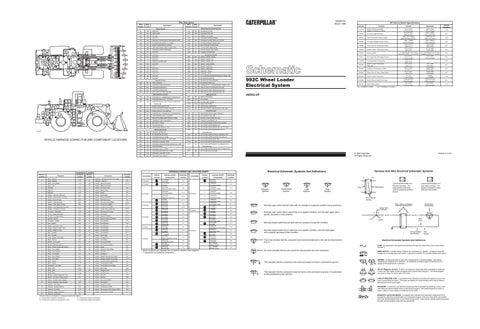
VEHICLE HARNESS CONNECTOR AND COMPONENT LOCATIONS
314
PU
STARTER RELAY NO. 2 OUTPUT
761
GY
LIFT KICKOUT SOL SW
321
BR
BACKUP ALARM/LAMP/TRAVEL ALARM
762
YL
BUCKET POSITIONER SOL SW
322
GY
WARNING HORN (FORWARD)
763
BU
TORQUE CONVERTER SW
326
PU
KEY SW “C” TERM.
803
BU
AUTO FIRE SUPPR SYSTEM SW POWER
327
PK
SHUTDOWN SOL
805
PK
AUTO FIRE SUPPR BRAKE SW
328
OR
SHUTDOWN MODULE “OFF”
807
BR
AUTO FIRE SUPPR NITROGEN SW TO CONT
808
PU
AUTO FIRE SUPPR NITROGEN SW TO
GN
AUTO FIRE SUPPR SYSTEM WARNING CKT
Machine Location 1
Component Alarm - Backup
Schematic Location D-12
Machine Location A
400
GN
SERVICE METER SW
403
GN
ALTERNATOR (R) TERM.
809
Component Solenoid - Nitrogen Actuator (Fire Supp)
Schematic Location F-3
404
YL
OPR MON HYD OIL TEMP
810
BU
AUTO FIRE SUPPR SYSTEM FAILURE CKT
405
GY
OPR MON OIL PRESS. (LO SETTING)
811
GY
AUTO FIRE SUPPR TEST CKT
406
PU
OPR MON COOLANT TEMP
812
GN
AUTO FIRE SUPPR NITROGEN ACTUATOR SOL
407
PK
OPR MON CONVERTER/RETARDER OIL TEMP
813
PK
AUTO FIRE SUPPR AGENT CYLINDER SW TO
409
OR
OPR MON NEUT
410
WH
OPR MON FAULT ALARM
814
YL
AUTO FIRE SUPPR AGENT SW TO AGENT SW
411
PK
OPR MON MASTER FAULT LAMP
816
BR
AUTO FIRE SUPPR ALARM
412
BU
OPR MON COOLANT FLOW
413
BR
OPR MON FUEL PRESS.
Connectors
Vehicle Location
F-11
*
Y-6W7257 Fire Detect Switch
C-9
C-8V1635 Diagnostic Connector
A-10
*
Y-6W7257 Fire Detect Switch
D-9
D-11
*
A-7
*
B-10
5
Alarm - Fire
F-2
23
Switch - Agent (Fire Supp)
F-11
3
Alternator
C-11
A
Switch - Aux Flood Lamp
E-5
4
Batteries
F-12
D
Switch - Backup Alarm
C-8
5
Batteries
A-12
A
Switch - Blower
D-5
C
Breaker - Alternator (80 Amp)
A-11
D
Switch - Brake (EMS)
F-8
B
Breaker - Blower Motor (10 Amp)
B-4
24
Switch - Bucket Positioner
B-1
*
C
Breaker - Key (10 Amp)
B-11
B
Switch - Cab Flood Lamp
F-5
3
C
Breaker - Main (80 Amp)
B-11
D
Switch - Converter Temp (EMS)
D-10
B
Breaker - Rear Wiper (3 Amp)
B-5
25
Switch - Coolant Flow (EMS)
E-11
B-11
26
Switch - Coolant Temp (EMS)
B-10
Breaker - Shutdown (15 Amp)
A-11
27
Switch - Coolant Temp (Start Aid)
B-10
C
Connector - Diagnostic
A-10
28
Switch - Discharge (Fire Supp)
F-10
C
Control - Engine Shutdown
A-11
29
Switch - Disconnect
C-11
6
Control - Fire Suppression
F-11
30
Switch - Engine Oil (EMS)
D-11
7
Controls - Kickout
A-9
31
Switch - Engine Oil (Service Meter)
D-11
A
Converter - Voltage
B-4
32
Switch - Fire Detection
C-9
B
Fuse - Holder
B-5
D
Switch - Fire Detection
D-9
B
Gauge - Converter Temp
E-5
33
Switch - Fire Detection
E-9
B
Gauge - Engine Coolant Temp
E-5
34
Switch - Fire Detection
E-11
B
Gauge - Hydraulic Temp
E-5
35
Switch - Fire Detection
C-11
8
Horn - Forward
B-2
36
Switch - Fire Detection
B-11
*
1 2 4 5
10 Contacts
5 4 1
9 Contacts
1 4 6
9
Horn - Forward
F-2
B
Switch - Flood Lamp
F-5
B
Lamp - Master Fault (EMS)
E-4
A
Switch - Forward Horn
D-4
B
Meter - Service
E-4
B
Switch - Front Wiper
D-4
B
Monitor - Fire Control
F-3
37
Switch - Fuel Level (EMS)
F-7
B
Monitor - Operator (EMS)
B-5
38
Switch - Fuel Pressure (EMS)
D-10
7
A
Motor - Blower (Heater and A/bs/C)
D-6
A
Switch - Heater
A-3
7
A
Motor - Floor Heater
A-2
39
Switch - Hydraulic Temp (EMS)
A-8
10
Motor - Front Washer
F-6
B
Switch - Key Start
D-5 C-1
A
Motor - Front Wiper
D-4
40
Switch - Lift Kickout
10
Motor - Rear Washer
E-6
A
Switch - Nitrogen Actuator (Fire Supp)
F-3
A
Motor - Rear Wiper
F-6
41
Switch - Nitrogen Actuator (Fire Supp)
F-10
11
Motor - Starter
E-10
B
Switch - Operator Monitor (EMS) Test
C-5
12
Motor - Starter
C-10
D
Switch - Parking Brake (EMS)
F-8
13
Receptacle - Aux Start
B-11
D
Switch - Parking Brake (Fire Supp)
F-9
C
Relay - Main
B-10
B
Switch - Rear Wiper
D-4
C
Relay - Start
A-10
42
Switch - Refrigerant A/C
B-11
C
Relay - Start
A-10
B
Switch - Running Lamp
F-5
14
Resistor - Starter/Diagnostic Conn
E-11
B
Switch - Start Aid
C-5
D
Sender - Converter Temp (Gauge)
D-11
B
Switch - Steering
B-9
15
Sender - Coolant Temp (Gauge)
C-10
D
Switch - Stop Lamp (EMS)
F-8
16
Sender - Hydraulic Temp (Gauge)
A-8
A
Switch - Thermostat
D-6
17
Solenoid - A/C Clutch
B-11
A
Switch - Torque Converter
A-4
18
Solenoid - Bucket Positioner
A-6
D
Switch - Transmission (EMS)
D-8
0
Solenoid - Converter
D-10
D
Switch - Transmission Filter Bypass (EMS)
D-8
19
Solenoid - Engine Shutdown
C-11
A
Switch - Transmission Neutral
C-8
20
Solenoid - Lift Kickout
A-5
Machine locations are repeated for components located close together. A = Components in operator's compartment C = Components located on relay panel D = Components located under platform B = Components in operator's compartment - Dash
7 Contacts
* *
Fire Supp. Agent (Pressure)
2270 kPa Max. (328.0 psi Max.)
1655 ± 138kPa (240.5 ± 20.0 psi)
N.O.
MAX HYD 3103kPa (MAX BYPASS SPOOL)
FORCE 66.7 N (MAX ACT 8.9 N)
N.O.
N.O.
3T9343
Power Train Filter Pressure (EMS)
6T6085
Fire Supp. Nitrogen Actuator (Press.)
1930 ± 138kPa (279.5 ± 20.0 psi)
1655 ± 138kPa (240.5 ± 20.0 psi)
N.O.
7N9560
Power Train Oil Temperature (EMS)
129.4 ± 2.8°C (265 ± 5°F)
118.3°C MIN (245°F MIN)
N.C.
7N9785
Engine Coolant Temperature (EMS)
107.2 ± 2.8°C (225 ± 5°F)
91 .0°C MIN (1 96°F MIN)
N.C.
7T2074
Steering (EMS)
11 L/min Max (25.4 mm ID line) [2.9 gal/min MAX (1.0 in. ID line)]
4.9 L/min MIN (25.4 mm ID line) [1.3 gal/min MIN (1.0 in. ID line)]
N.C.
7T4371
Fire Suppression Discharge Pressure
93 ± 21 kPa (13.5 ± 3.0 psi)
69 ± 21 kPa (10.0 ± 3.0 psi)
N.O.
7T4785
Fire Suppression Temperature
193.3 ± 8°C (380 ± 15°F)
8N1 693
Engine Coolant Temperature (Start Aid)
37.8 ± 2.8°C (100 ± 5°F)
26.7°C MIN (80°F MIN)
N.C.
8N2248
Hydraulic Oil Temperature (EMS)
101.7 ± 2.8°C (215 ± 5°F)
93.3°C MIN (200°F MIN)
N.C.
9G3341
Power Train Oil Temp. (Filter) (EMS)
51.7 ± 2.8°C (125 ± 5°F)
43.0°C MIN (110°F MIN)
N.C.
9W2343
Engine Coolant Flow (EMS)
37 ± 3g (1.3 ± 0.1 oz)
31gMIN (1.1 oz MIN)
N.O.
9W2653
Brake Pressure (EMS) (Fire Supp)
(1200 psi MAX) 8270 kPa MAX
(1000 ± 50.0 psi) 6890 ± 345 kPa
N.C.
9W3187
Fuel Pressure (EMS)
93 ± 21kPa (13.5 ± 3.0 psi)
69 ± 21kPa (10.0 ± 3.0 psi)
N.C.
N.O. = NORMALLY OPEN
-
N.O.
N.C. = NORMALLY CLOSED
F-8Vl6l9 N-8V1618 A-9V4483 N-8V1618 C-8V1635 N-8V1618 A-9V4483 K-7V9818 A-9V4483 D-7V9513 A-9V4483 G-7V9835 A-9V4483 K-7V9818 B-6W7259 M-6W7258 A-9V4483 H-9V4426 A-9V4483 K-7V9818 B-6W7259 Y - 6W7257 C-8V1635 Engine Shutdown Control M-6W7258 Fire Monitor Control N-8Vl6l8 XX-6W3354 N-9V4455 XX-6W3354
Printed in U.S.A.
F-3
6 Contacts
5 Contacts
4
B-3
5
C-3
4
E-3
*
C-7
8
C-6
*
E-3
4 Contacts
*
E-1
7
A-11
77
F-3
7
A-7
*
A-7
*
Vehicle locations are repeated for connectors located close together. * = Connector is located at component
Harness And Wire Electrical Schematic Symbols
N-8V1618 W-9C2169 Y-6W7257 Fire Detect Switch Y-6W7257 Fire Detect Switch
Schematic Location
B-6W7259 Fire Supp Control
A
Breaker - Running Lamps (10 Amp)
Harness And/Or Components
*
F-11
B
Vehicle Location
*
F-8
Switch - Agent (Fire Supp)
C
Connectors
B-5
2
Solenoid - Start Aid
22
12 Contacts
Schematic Location
*
25 Contacts
21
C-4
20 Contacts
Harness And/Or Components
A-11
1
C-12
Alarm - Fault (EMS)
69 ± 21 kPa (10.0 ± 3.0 psi)
Electrical Schematic Symbols And Definitions
B-7
37 Contacts
Alarm - Backup
93 ± 21 kPa (13.5 ± 3.0 psi)
© 1990 Caterpillar All Rights Reserved
7
2
Engine Oil Pressure (EMS) Engine Oil Pressure (S. Meter)
NITROGEN SW
A - 9V4483 N-8V1618 C - 8V1 635 F-8Vl619 A-9V4483 Operator Monitor (EMS)
A
Deactuate
NITROGEN SW
HARNESS CONNECTOR LOCATION CHART
Component Location
Normal Condition
Actuate
Control Circuits
Monitoring Circuits
C32237P1
992C Wheel Loader Electrical System
Function
49Z932-UP
Lighting Circuits
302
Part No.
3T9342
Accessory Circuits
Basic Machine Circuits
Off Vehicle Switch Specifications
3T4418
OPR MON LO FUEL
102
Ground Circuits
A
SENR4761 March 1990
Wire Description
Y-6W7257 Fire Detect Switch Y-6W7257 Fire Detect Switch K-7V9818 L-7V0007 J-3T2086 T-3T2087 A-9V4483 D-7V9513 A-9V4483 Not Used A-9V4483 Front Wiper Motor AA-9V0960 N-8Vl6l8 B-6W7259 Discharge Sw (Fire Supp) H-9V4426 Rear Wiper Motor N-8V1618 Not Used N-8V1618 V-6W0642 N-8V1618 U-8V1600 XX - 6W3354 Kickout Control XX - 6W3354 Kickout Control
A
AA
F-7
Typical representation of a Deutsch connector. The plug contains all sockets and the receptacle contains all pins.
E-11 C-11
T
Pressure Symbol
Temperature Symbol
Level Symbol
Flow Symbol
Receptacle
Plug 2
E-5 D-6 B-3
Wire, Cable, or Harness Assembly Identification
Normally open switch that will close with an increase of a specific condition (temp-press-etc.).
E-11
Normally open switch that is closed due to an applied condition, and will open again with a specific decrease in that condition.
C
A
A 325-PK-14
Pin
D-8
AA 1
2
Normally closed switch that is open due to an applied condition, and will close again with a specific decrease in that condition.
9X-1123 325-PK-14
Wire Color
Socket
Normally closed switch that will open with an increase of a specific condition.
F-10 F-6
Component Part Number
Single Wire Connector
F-2 D-4
Typical representation of a Sure-Seal connector. The plugand receptacle contain both pins and sockets.
Pin or Socket Number
E-9 B-11
1 2
1 2
1
200-BK-14
Circuit Number Identification
Wire Gauge
C-8 B-8 A-9
Electrical Schematic Symbols And Definitions
The circle indicates that the component has screw terminals and a wire can be disconnected from it.
FUSE - A component in an electrical circuit that will open the circuit if too much current flows through it.
A-9
No circle indicates that the wire cannot be disconnected from the component.
This indicates that the component has a wire connected to it that is connected to ground.
This indicates that the component does not have a wire connected to ground. It is grounded by being fastened to the machine.
REED SWITCH - A switch whose contacts are controlled by a magnet. A magnet closes the contacts of a normally open reed switch; it opens the contacts of a normally closed reed switch.
T
SENDER - A component that is used with a temperature or pressure gauge. The sender measures the temperature or pressure. Its resistance changes to give an indication to the gauge of the temperature or pressure. RELAY (Magnetic Switch) - A relay is an electrical component that is activated by electricity. It has a coil that makes an electromagnet when current flows through it. The electromagnet can open or close the switch part of the relay. CIRCUIT BREAKER (C/B) - A component in an electrical circuit that will open the circuit if too much current flows through it. This does not destroy the circuit breaker and it can be reset to become part of the circuit again. SOLENOID - A solenoid is an electrical component that is activated by electricity. It has a coil that makes an electromagnet when current flows through it. The electromagnet can open or close a valve or move a piece of metal that can do work. MAGNETIC LATCH SOLENOID - A magnetic latch solenoid is an electrical component that is activated by electricity and held latch by a permanent magnet. It has two coils (latch and unlatch) that make electromagnet when current flows through them. It also has an internal switch that places the latch coil circuit open at the time the coil latches.