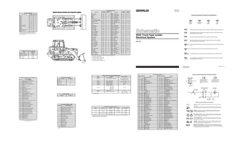
Connector Location¹
Machine Harness Connector And Component Locations
Schematic Location
Machine Location
CONN 2
C-7
19
CONN 3
C-7
19
CONN 4
C-7
19
CONN 5
C-7
19
CONN 6
C-7
19
CONN 7
B-6
E
CONN 8
B-6
E
CONN 9
C-5
16
Connector Number CONN 1
C-8
CONN 10
B-5
9
CONN 11 Harness Code
A-5
E
CONN 12 Service Tool
A-5
E
CONN 13
B-4
8
CONN 14
D-4
27
CONN 15
D-3
31
CONN 16 Caterpillar Monitoring System Harness Code
C-2
A
CONN 17
C-1
30
10
18
3
C
5
7
2
25
9 4
20
19
13 22
8
D
15
14
21 18
23
27
A
24
32
6
31
16
12 1
23
17 28
30
26
B
11 29
E
¹The connectors shown in this chart are harness to harness and special use connectors. Connectors which join a harness to a component are generally located at on near the component. See the component location chart.
D
9
11
25
12 C
8
Related Electrical Service Manuals Title
SENR4757
Caterpillar Monitoring System
RENR2014
Electronic Hydrostatic Control
SENR8314
28 19
15
21 3 1
32
22
26
Form Number
Alternator: (132-2156)
E
20
2
24
6
23
7
4
A
B
10
16 5
31
13
27
30
29 17
23
14
SENR3581
Consist: 106-8557
SENR3859
Machine Location A
Alarm - Backup
C-8
1
Sender - Trans Oil Temp
B-7
14
Alternator
D-8
2
Sensor - Bucket Positioner
C-1
27
Battery
A-8
32
Sensor - Center Pedal
B-2
15
Battery
D-8
3
Sensor - Charge Pressure
C-5
16
Breaker - Alt
A-6
E
Sensor - Coolant Temp
C-8
2
Caterpillar Monitoring System
A-2
A
Sensor - Hydraulic Oil Temp
C-1
17
Control - Electronic Hydrostatic
A-5
E
Sensor - Left Steering Pedal
B-2
15
Control - Pilot Valve
A-4
B
Sensor - Lift Kickout
C-1
28
Converter
B-4
D
Sensor - Right Steering Pedal
B-2
15
Diode - Arc Suppressor
B-8
4
Sensor - RPM
A-6
18
Fuses
A-7
E
Sensor - RPM
C-6
18
Gauge Cluster
D-2
A
Sensor - Speed/Direction
D-3
19
Ground - Cab Roof
C-4
D
Solenoid - A/C Clutch
B-8
4
Ground - Dash
C-2
A
Solenoid - Engine Shutdown
B-8
20
Ground - Engine
D-7
5
Solenoid - Left Forward
C-5
16
Ground - Engine
D-8
2
Solenoid - Left Rev
C-5
16
Ground - Engine
D-8
2
Solenoid - Override
C-5
16
Ground - Front Frame
D-2
6
Solenoid - Park Brake
C-5
16
Ground - Left Frame
C-7
3
Solenoid - Right Forward
C-5
16
Ground - Left Frame
A-8
3
Solenoid - Right Rev
C-5
16
Ground - Platform
D-2
6
Solenoid - Start Aid
D-7
21
Ground - Rear Frame
D-7
3
Solenoid - Sync
C-5
22
Heater - Air Inlet
D-7
7
Switch - A/C High/Low
B-8
4
Horn - Forward
D-1
6
Switch - Air Inlet Heater
C-2
A
Lamp - Action
B-2
A
Switch - Blower
B-4
B
Lighter - Cigar
B-2
A
Switch - Clear
A-4
23
Motor - Blower
B-5
8
Switch - Disconnect
A-8
21
Component Sender - Fuel Level
Schematic Location D-1
Machine Location 13
Motor - Condenser
B-5
9
Switch - Engine Oil
B-7
24
Motor - Front Washer
D-4
10
Switch - Forward Horn
C-3
C
Motor - Front Wiper
D-4
11
Switch - Front Wiper
C-4
25
Motor - Rear Washer
D-4
10
Switch - Governor Lever
C-3
C
Motor - Rear Wiper
D-4
12
Switch - Key Start
B-2
A
Motor - Starter
D-7
5
Switch - Lamp
C-2
A
Radio
B-4
D
Switch - Operator/Start Aid
C-2
A
Relay - Air Inlet Heater
D-7
7
Switch - Rear Wiper
C-4
25
Relay - Main
A-7
E
Switch - Sensor/Speed Cal
A-4
23
Relay - Start
A-6
E
Switch - Service
A-4
23
Relay Assembly
B-5
9
Switch - Start Aid Temp
C-8
2
Resistor - Blower Motor
B-5
8
Switch - Thermostat
B-5
8
Resistor - Dimming
D-2
A
Switch - Trans Control Brake
D-3
C
Sender - Engine Speed
B-7
5
Switch - Travel
C-3
A
SENR1832 April 1999
Electrical Schematic Symbols And Definitions
T
Temperature Symbol
Pressure Symbol
Flow Symbol
Level Symbol
Normally open switch that will close with an increase of a specific condition (temp-press-etc.). Normally open switch that is closed due to an applied condition, and will open again with a specific decrease in that condition.
963C Track-Type Loader Electrical System
Normally closed switch that will open with an increase of a specific condition.
Normally closed switch that is open due to an applied condition, and will close again with a specific decrease in that condition.
2DS1-UP
The circle indicates that the component has screw terminals and a wire can be disconnected from it.
No circle indicates that the wire cannot be disconnected from the component.
This indicates that the component has a wire connected to it that is connected to ground.
Machine locations are repeated for components that are located close together. A = Components located on Dash.
Starter Motor: (104-7040) Consist: 6V-5720
Alarm - Action
Schematic Location D-4
Component
1
Component Location
B = Components located on Right Console.
This indicates that the component does not have a wire connected to ground. It is grounded by being fastened to the machine.
C = Components located on Left Console. D = Components located in Headliner. E = Components located on Relay/Fuse Panel.
E86878
Printed in U.S.A.
© 1999 Caterpillar All Rights Reserved
Part No.
Component Identifiers (CID¹ ) and Module Identifiers (MID²)
CID No.
Component
Caterpillar Monitoring System (MID No. 30)
Monitoring System Mode Mode of Operation
Mode Number
Resistor, Sender, and Solenoid Specifications Component
3E-6332
Solenoid - Start Aid
4W-9972
Sender - XMSN Oil Temperature
Resistance (Ohms)¹ 6 560 to 716 @ 54ºC (130ºF) 72 to 82 @ 110ºC (230ºF)
Normal
0
Harness Code
1
6V-2455
Sender - Engine Speed
Harness And Wire Electrical Schematic Symbols
Wire Description Chart
110 - 200
Wire Number
Wire Color
Wire Number
Wire Color
101
RD
Bat (+)
506
PU
Washer - Front
102 105
BU
Hd Lmp
507
WH
Washer - Rear
BR
Key Sw
508
PU
Radio Speaker - Left
109
OR
Alt Output (+) Term.
509
WH
Radio Speaker - Left (Common)
112
PU
Main Power Rly Output
511
BR
Radio Speaker - Right
Description Power Distribution Circuits
Description
0096
Fuel Level Sender
Parameter Display
2
9G-1950
Resistor - A/C Motor
Overall 2.0 ± .1; Tap 1.0 ± .05
0110
Engine Coolant Temperature Sensor
Service
3
101-1759
Solenoid - A/C Clutch
14.4 ± 0.6
113
OR
Opr Mon Panel B (+) Switched
512
GN
Radio Speaker - Right (Common)
0177
Torque Converter Oil Temperature Sensor
Digital Tattletale
4
116-4152
Solenoid - Park Brake
34.3 ± 1.7
114
GN
Warning Horn (Forward)
513
OR
A/C Compressor/Refrigerant Pressure SW
0248
Data Link
Electronic Hydrostatic Control
5
116-6203
Resistor - Dimming
116
BR
Aux Ckt
515
GY
Blower Motor (HI)
118
GY
Aux Ckt
516
GN
Blower Motor (Medium)
0263
8 Volt Sensor Power Supply
124
GN
A/C
517
BU
Blower Motor (Low)
0271
Action Alarm
128
PK
Aux Ckt
521
YL
A/C SW To Refrigerant SW
0324
Action Lamp
129
BU
Aux Ckt
522
WH
A/C Clutch To Thermostat SW
0600
Hydraulic Oil Temperature Sensor
Right Reverse
158
BR
Aux Ckt
592
BU
DC/DC Converter Power Output
0601
Brake Air Pressure
Override
160
PU
Aux Ckt
A513
PK
DC/DC Converter Memory Output
0819
Display Data Link
164
WH
Hydro Ctrl
0821
9 Volt Display Power Supply
600
BR
Dash Lamp Basic
200
BK
Main Chassis
610
OR
Head Lamp Basic
0830
Brake Oil Temperature
201
BK
Operator Monitor Return
615
YL
Cab Flood Lamp/Rops
202
BK
XMSN Ctrl
663
GY
Gauge Lamps - CAT Mon Sys
260
BK
TEHC Ident Code 0
261
BK
TEHC Ident Code 1
761
GY
Lift Kickout Sol SW
262
BK
TEHC Ident Code 2
762
YL
Bucket Positioner Sol SW
263
BK
TEHC Ident Code 3
799
WH
Sensor Power
270
BK
CAT Mon Sys Ident Code 0
C744
PU
Parking Brake - Sol To SW
271
BK
CAT Mon Sys Ident Code 1
E707
GN
Display +V
272
BK
CAT Mon Sys Ident Code 2
E708
PK
Display Clock
273
BK
CAT Mon Sys Ident Code 3
E735
PU
CAT Mon Sys Tack/Serv Mtr/Odometer Select
274
BK
CAT Mon Sys Ident Code 4
F743
GY
Impl Lift Prop Sol 2
Solenoids - Left Forward Left Reverse 130-3310
Parking Brake Switch
0110
Engine Coolant Temperature Sensor
0168
Electrical System Voltage
0190
Engine RPM Sensor
0269
Sensor Supply Voltage
Right Forward
130-6913
Solenoid - Sync
155-4652
Solenoid - Engine Shutdown
7.75 ± 1.00
33.6 Latch - 1.55 ± 10% Unlatch - 10.3 ± 10%
¹ At room temperature.
Machine Code
Electronic Hydrostatic Control (MID No. 79) 0070
20 ± 1
Sales Model
Machine Code
963C
010
Ground Circuit
0299
Transmission Lever Position Sensor
0349
Transmission Sync Solenoid
275
BK
CAT Mon Sys Ident Code 5
F780
PK
Parking Brake SW
0358
Pilot Pressure Supply Actuator
290
BK
CAT Mon Sys Service
F793
OR
Air Inlet Heater Relay
0463
Implement Dual Pressure Relief Solenoid
291
BK
CAT Mon Sys Clear
F794
BU
Lift SW (N.C.)
0464
Implement Tilt Lever Position Switch
Basic Machine Circuits
F795
YL
Lift SW (N.O.)
0465
Governor Control Lever Switch
0
Data valid but above normal operational range.
0466
Left Track Steering Pedal Position Sensor
1
Data valid but below normal operational range.
0467
Right Track Steering Pedal Position Sensor
2
Data erratic, intermittent, or incorrect.
0468
Service Brake Pedal Position Switch
3
Voltage above normal or shorted high.
0469
Left Track Forward Direction Solenoid
4
Voltage below normal or shorted low.
0470
Left Track Reverse Direction Solenoid
5
Current below normal or open circuit.
0471
Right Track Forward Direction Solenoid
6
Current above normal or grounded circuit.
0472
Right Track Reverse Direction Solenoid
7
Mechanical system not responding properly.
0473
Charge Pressure Sensor
8
Abnormal frequency, pulse width, or period.
0589
Travel Speed Switch
9
Abnormal update.
0617
Air Inlet Heater Relay
10
Abnormal rate of change.
0650
Harness Code
11
Failure mode not identifiable.
0681
Parking Brake Solenoid
12
Bad device or component.
13
Out of calibration.
14
Parameter failures.
15
Parameter failures.
16
Parameter not available.
17
Module not responding.
18
Sensor supply fault.
19
Condition not met.
20
Parameter failures.
The CID is a diagnostic code that indicates which component is faulty. The MID is a diagnostic code that indicates which electronic control module diagnosed the fault.
Failure Description
The FMI is a diagnostic code that indicates what type of failure has occurred.
Off Machine Switch Specification Part No.
Function
Actuate
Deactuate
Contact Position
3E-6449
Start Aid Temperature
38.0 ± 3.0 ºC
27.0 º C
Normally
100.4 ± 5.4ºF
80.6 ºF
Closed
3E-7692 114-5333
Engine Oil Refrigerant Pressure (AC)
301
BU
Starter No. 1 Sol
F796
GY
Engine Speed
304
WH
Starter Relay No. 1 Output
822
PK
Forward Hydrst Sync Sol
306
GN
Starter Relay Coil
828
WH
Hydrst Left Ster Pedal Sensor
308
YL
Main Power Relay Coil
829
GN
Hydrst Pedal Sensor
310
PU
Start Aid SW To Start Aid Sol
830
OR
Hydrst Right Ster Pedal Sensor
311
WH
Start Aid Sol To Temp SW
831
PK
Hydrst Eng Speed Sensor
WH
Hydrst Throttle N/O SW
113.0kPa MAX
70.0 ± 20.0kPa
Normally
321
BR
Bckp Alarm
836
16.4psi MAX
10.2 ± 2.9psi
Open
322
GY
Warning Horn (Forward)
837
GN
Hydrst Throttle N/C SW
275 to 1750 kPa¹
--
Normally ²
326
PU
Key SW "C" Term.
843
WH
Hydrst Left Pump Forward Sol
40 to 255 psi
--
Open
844
GN
Hydrst Left Pump Reverse Sol
403
GN
Alternator (R) Term.
848
GY
Hydrst Speed Reverse Sol
405
GY
Opr Mon Oil Press. (Low Setting)
849
YL
Hydrst Right Pump Reverse Sol
410
WH
Opr Mon Action Alarm
850
PU
Hydrst Right Pump Forward Sol
411
PK
Opr Mon Master
851
WH
Hydrst Speed And Direction Sensor
419
YL
Opr Mon Parking Brake
852
GN
Hydrst Charge Press. Sensor
441
OR
Eng Coolant Temp Gauge
892
BR
CAT Data Link (-)
442
GY
Hyd System Temp Gauge
893
GN
CAT Data Link (+)
443
YL
Power Train Temp Gauge
F842
BU
AIH Post Heat
447
PK
Fuel Level Gauge
975
WH
Sol Return
C413
YL
Display Data
E900
WH
Trans Output SPD (+)
C414
BU
Display Load
E901
GN
Trans Output SPD (-)
E902
PU
Trans Intermediate SPD (+)
YL
Trans Intermediate SPD (-)
¹ A hysteresis band exists: with increasing pressure the closed condition can be maintained up to 2800 kPa (405 psi), with decreasing pressure the closed condition can be maintained down to 170 kPa (25 psi). ² Contact position at the contacts of the harness connector.
Monitoring Circuits
Accessory Circuits 500
BR
Wiper - Front (Park)
E903
501
GN
Wiper - Front (Low)
G939
PK
Hydro Cont Switch Return
502
OR
Wiper - Front (HI)
K997
BU
(+) V Sensor, CAT Mon Sys
503
BR
Wiper - Rear (Park)
R985
WH
Travel Speed SW Travel Mode
504
YL
Wiper - Rear (Low)
R986
BU
Travel Speed SW Work Mode
505
BU
Wiper - Rear (HI)
Typical representation of a Deutsch connector. The plug contains all sockets and the receptacle contains all pins.
Receptacle
Plug
1 2
1 2
1
2
Typical representation of a Sure-Seal connector. The plugand receptacle contain both pins and sockets.
Pin or Socket Number Wire, Cable, or Harness Assembly Identification
Component Part Number
Single Wire Connector C
A
A 325-PK-14
Pin
Control Circuits
Hydrostatic Transmission Electronic Control Module
Failure Mode Identifiers (FMI)
AA
Lighting Circuits
0296
FMI No.
A
Accessory Circuits (cont'd)
AA 1
9X-1123 325-PK-14
Wire Color
Socket
2
200-BK-14
Circuit Number Identification
Wire Gauge
Electrical Schematic Symbols And Definitions FUSE - A component in an electrical circuit that will open the circuit if too much current flows through it. REED SWITCH - A switch whose contacts are controlled by a magnet. A magnet closes the contacts of a normally open reed switch; it opens the contacts of a normally closed reed switch.
T
SENDER - A component that is used with a temperature or pressure gauge. The sender measures the temperature or pressure. Its resistance changes to give an indication to the gauge of the temperature or pressure. RELAY (Magnetic Switch) - A relay is an electrical component that is activated by electricity. It has a coil that makes an electromagnet when current flows through it. The electromagnet can open or close the switch part of the relay. CIRCUIT BREAKER (C/B) - A component in an electrical circuit that will open the circuit if too much current flows through it. This does not destroy the circuit breaker and it can be reset to become part of the circuit again. SOLENOID - A solenoid is an electrical component that is activated by electricity. It has a coil that makes an electromagnet when current flows through it. The electromagnet can open or close a valve or move a piece of metal that can do work. MAGNETIC LATCH SOLENOID - A magnetic latch solenoid is an electrical component that is activated by electricity and held latch by a permanent magnet. It has two coils (latch and unlatch) that make electromagnet when current flows through them. It also has an internal switch that places the latch coil circuit open at the time the coil latches.