Connector Location
Schematic Location
Machine Location
CONN 2
D-11
12
CONN 3
D-11
12
CONN 4
D-11
12
CONN 5
A-11
14
CONN 6
A-11
33
CONN 7
F-9
34
CONN 8
D-9
27
CONN 9
C-9
14
1
CONN 10
B-9
11
CONN 11
B-9
11
8 24
CONN 12
B-9
11
CONN 13
B-9
11
Connector Number CONN 1
E-11
RENR3561 June 2000
3
CONN 14
B-9
11
CONN 15
A-9
11
CONN 16
A-9
11
CONN 17
F-5
A
CONN 18
E-5
A
CONN 19
C-4
A
CONN 20
C-4, D-4
A
CONN 21
D-4
A
CONN 22
B-2, B-3
5
CONN 23
F-1
A
CONN 24
F-1
A
CONN 25
D-12
7
CONN 26
A-9
11
32 3
16
2
10
6
23
28 12
21 22 30 35
20
7
29 27 31
19
17 15
18
C A
33 2
10
14
1
9
13
B 34 D 11 25 5
6 4
26
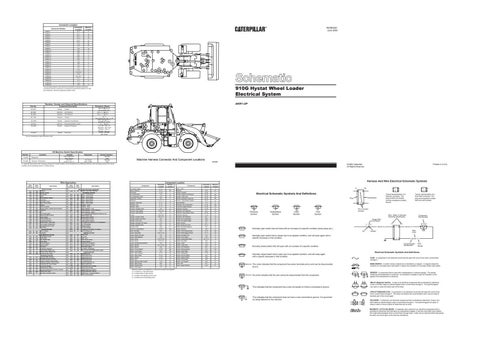
910G Hystat Wheel Loader Electrical System
The connectors shown in this chart are for harness to harness connectors. Connectors that join a harness to a component are generally located at or near the component. See the Component Location Chart.
Part No.
Resistor, Sender and Solenoid Specifications Component Description
4W-9972
Sender:
6E-4664
Solenoid:
Lift Positioner
6E-4665
Solenoid:
Tilt Positioner
9G-1950
Resistor:
Resistor
104-3008
Sender:
Hydraulic Temperature
122-4973
Solenoid:
Proportional (Motor) Valve
155-4032
Sender:
Engine Oil Pressure
172-4270
Sender:
Fuel Level
2
Resistance (Ohms)¹
560-716 @ 54.4°C 72.1-81.8 @ 110°C 20.6 ± 1.7 @ 25°C
Coolant
20.6 ± 1.7 @ 25°C 2 ± .1 Each Side of the Tap: 1 ± .05 5806-7264 @ 54.4°C 524-586 @ 115.6°C 7.75 ± 1 @ 25°C 0-21 kPa: 240 ± 15 48.3 kPa: 192 ± 27.5 276 kPa: 102 ± 11 552 kPa: 33.5 ± 14 Empty: 240-265 Full: 20-35
¹ At room temperature unless otherwise noted.
30 24 21 32 35 16 1
Function
114-5333
Refrigerant
104-3008
Hydraulic Temperature
Off Machine Switch Specification Actuate
275 to 2800 kPa¹ (40 to 406 psi) 102 ± 3°C (215.6 ± 37.4 °F)
Deactuate
--95 °C MIN (203 °F MIN)
B 14 23 D 11 25
A
18
9
4 5 27
22 8
Part No.
C
19 33 3 10 17 12 7 15 28
AKR1-UP
6
34
20
31
26
29
13
Contact Position Normally Open Normally Open
Machine Harness Connector And Component Locations
E97888
Wire Description Wire Number 101 102 105 109 112 114 115 117 118 120 122 123 124 127 128 129 130 158 160 161 181 188 200 202 304 306 307 308 310 321 322 327 330 331 373 403 419 441 442 443 447 449 464 483 C444
Wire Color
Description
Power Circuits Battery + RD Marker Lamps RD Key Switch RD Alt B+ RD Main Breaker Output PU Fwd Horn RD Fwd Horn/ Turn RD Main Power Relay RD Wipers GY Sw'd Converter YL Backup Alarm/ Lights/ Service Meter RD Lamp Sw WH A/C GN Aux Flood Lights OR Kickout & Ride Control PK Cigar Lighter BU Service Brake Sw RD Condensor Motors BR Start Aid Rly - AIH Lamp PU Turn Fuse to Flasher As. PK Eng Speed Ctrl (+) Bat GY AIH Timer WH Ground Circuits Main Chassis BK Controller BK Basic Machine Circuits Start Relay Output WH Start Relay GN Key Switch Start OR Main Relay YL Start Aid Signal PU Backup Alarm BR Fwd Horn GY Shutdown Solenoid PK Neutral Start Relay Coil YL Backup Alarm Relay Coil OR AIH Sw to AIH Timer GN Monitoring Circuits Alternator (R) Terminal GN Operator Monitor Test Sw YL Engine Coolant Temp Gauge OR Hydraulic System Temp Gauge GY Converter Oil Temp Gauge YL Fuel Level Gauge PK Speedometer Signal BU Opr Mon Panel Eng Oil Press. Sender GY Brake Fluid Level BR Alternator Indicator Lamp YL
Wire Number C446 500 501 502 503 504 505 506 507 508 509 511 513 515 516 517 518 521 522 537 567 593 A514 604 605 606 608 610 611 614 615 619 665 720 752 754 755 761 762 F747 F765 G742 922 923 975 976
Harness And Wire Electrical Schematic Symbols
Component Location
Wire Color
Description
Monitoring Circuits (continued) Power Train Filter Warning PK Accessory Circuits Wiper - Front (Park) BR Wiper - Front (Low) GN Wiper - Front (High) OR Wiper - Rear (Park) BR Wiper - Rear (Low) YL Wiper - Rear (High) BU Washer - Front PU Washer - Rear WH Radio Speaker - Left PU Radio Speaker - Left (Common) WH Radio Speaker - Right BR A/C Compressor/Refrigerant Pressure Sw OR Blower Motor (HI) GY Blower Motor (MED) GN Blower Motor (LOW) BU COSA Flasher Signal OR A/C High/Low Press Sw To Compressor YL A/C Thermostat WH Flasher Output GN A/C SW Jumper WH Condensor Fan Relay To Motors GN SW To Relay Coil YL Lighting Circuits Stop Lamp OR Left Turn YL Right Turn GY Rear Flood Lamps GN Dimmer Switch OR High Beam Headlights PU Park/Tail/Dash Lamps PU Cab Flood Lights YL Low Beam Headlights GN SW To Left Front / Right Rear Lights BR Control Circuits Neutralizer Sw PU XMSN Solenoid 2 YL XMSN Solenoid 3 BU XMSN Solenoid 4 OR Lift Positioner Sol GY Bucket Positioner Sol YL Speed Select Sw OR Park Brake SW To Relay BR Relay Coil to Diode GN XMSN Solenoid 2 Return BR XMSN Solenoid 3 Return GY XMSN Cont - Solenoid Return WH Ride Control Output OR
Schematic Machine Location Location Air Intake Heater E-12 21 Alarm- Backup E-11 24 Alternator C-12 7 Arc Suppressor C-4 A Arc Suppressor Atch F-2 A Assembly- Flasher E-5 C Batteries C-10, C-11 10 Breaker- Alternator F-11 3 Breaker- Aux F-11 3 Breaker- Main F-11 3 Control- Indicator Atch F-2 A Control- Over Speed F-8, F-9 D Control- Shift Handle F-4 A Fuses D-8, E-8 D Gauge- Coolant Temp E-3, F-3 A Gauge- Engine Oil Press E-4 A Gauge- Fuel Level E-3 A Gauge- Hydraulic Oil Temp F-4 A Gauge- Speedometer E-3 A Ground- Cab A-9 11 Ground- Engine Block D-12 20 Horn- Forward D-1 4 Lamp- Assembly A-12, F-12 1 Lamp- Brake Oil Level F-6 A Lamp- Filter Bypass F-6 A Lamp- Flood C-10, E-10 2 Lamp- Flood C-3, F-3 6 Lamp- Flood/Park Brake/Alt C-6 A Motor- Blower A-11, A-12 17 Motor- Blower D-9 27 Motor- Front Washer A-10 26 Motor- Front Wiper D-3 18 Motor- Rear Washer A-10 26 Motor- Rear Wiper E-10 19 Motor- Starter C-12 12 Relay- AIH F-11 3 Relay- Backup Alarm/Lights C-8 D Relay- Main Power E-8 D Relay- Neutral Start C-9 D Relay- Park Brake C-8 B Machine locations are repeated for components located close together. A = Located on or near dash panel. B = Located inside of right console. Component
C = Located in the steering column area. D = Located around Fuse/relay panel.
Printed in U.S.A.
© 2000 Caterpillar All Rights Reserved
¹ A hysteresis band exists: with increasing pressure the closed condition can be maintained up to 2800 kpa (405 psi), with decreasing pressure the closed condition can be maintained down to 170 kpa (25 psi).
Component Relay- Start Resistor Sender- Coolant Sender- Engine Oil Pressure Sender- Fuel Level Sender- Hydraulic Temp Sw Sensor- Transmission Speed Service Meter Solenoid- A/C Compressor Solenoid- Engine Shutoff Solenoid- Forward Solenoid- Lift Positioner Solenoid- Prop (Motor) Valve Solenoid- Reverse Solenoid- Tilt Positioner Switch- A/C Compressor Switch- Air Intake Heater Switch- Blower Switch- Brake Oil Level Switch- Bucket Positioner Switch- Dimmer Switch - ATCH Disconnect Switch- Filter Bypass Press Switch- Forward Horn Switch- Front Wiper Switch- Intermittent Wiper Switch- Key Start Switch- Lamp Switch- Lamp Test Switch- Lift Positioner Switch- Parking Brake Switch- Rear Wiper Switch- Refrigerant Switch- Service Brake Switch- Speed Select Switch- Thermostat Switch- Turn Signal Timer- AIH Timer- Engine Shutoff
Schematic Location F-11 D-9 D-12 D-12 E-12 B-12 B-12 F-4 C-12 D-12 F-12 E-1 B-12 F-12 D-1 D-6 E-6 E-7 E-11 D-1 D-3 C-11 E-11 F-4 C-5 E-7, F-7 D-4 F-5 E-6 D-1 F-9 B-5 D-12 D-3 D-6 D-9 E-5 E-7 E-9
Machine Location 3 27 7 22 15 28 29 C 30 16 8 13 31 8 13 B A B 3 9 C 35 32 A A A C A A 4 23 A 30 B B 27 C A D
A
AA
Electrical Schematic Symbols And Definitions
Typical representation of a Deutsch connector. The plug contains all sockets and the receptacle contains all pins.
Receptacle
Plug 2
Temperature Symbol
Level Symbol
Typical representation of a Sure-Seal connector. The plug and receptacle contain both pins and sockets.
Pin or Socket Number
T
Pressure Symbol
1 2
1 2
1
Flow Symbol
Wire, Cable, or Harness Assembly Identification
Component Part Number
Single Wire Connector C
A
A 325-PK-14
Normally open switch that will close with an increase of a specific condition (temp-press-etc.). Pin
Normally open switch that is closed due to an applied condition, and will open again with a specific decrease in that condition.
AA 1
9X-1123 325-PK-14
Wire Color
Socket
2
200-BK-14
Circuit Number Identification
Normally closed switch that will open with an increase of a specific condition.
Wire Gauge
Electrical Schematic Symbols And Definitions
Normally closed switch that is open due to an applied condition, and will close again with a specific decrease in that condition.
FUSE - A component in an electrical circuit that will open the circuit if too much current flows through it.
The circle indicates that the component has screw terminals and a wire can be disconnected from it.
REED SWITCH - A switch whose contacts are controlled by a magnet. A magnet closes the contacts of a normally open reed switch; it opens the contacts of a normally closed reed switch.
No circle indicates that the wire cannot be disconnected from the component.
SENDER - A component that is used with a temperature or pressure gauge. The sender measures the temperature or pressure. Its resistance changes to give an indication to the gauge of the temperature or pressure.
This indicates that the component has a wire connected to it that is connected to ground.
This indicates that the component does not have a wire connected to ground. It is grounded by being fastened to the machine.
T
RELAY (Magnetic Switch) - A relay is an electrical component that is activated by electricity. It has a coil that makes an electromagnet when current flows through it. The electromagnet can open or close the switch part of the relay. CIRCUIT BREAKER (C/B) - A component in an electrical circuit that will open the circuit if too much current flows through it. This does not destroy the circuit breaker and it can be reset to become part of the circuit again. SOLENOID - A solenoid is an electrical component that is activated by electricity. It has a coil that makes an electromagnet when current flows through it. The electromagnet can open or close a valve or move a piece of metal that can do work. MAGNETIC LATCH SOLENOID - A magnetic latch solenoid is an electrical component that is activated by electricity and held latch by a permanent magnet. It has two coils (latch and unlatch) that make electromagnet when current flows through them. It also has an internal switch that places the latch coil circuit open at the time the coil latches.