Wire Description
SENR5897 January 1996 FMI No.
Wire Number
0
Data valid but above normal operational range.
1
Data valid but below normal operational range.
2
Data erratic, intermittent, or incorrect.
3
Voltage above normal or shorted high.
4
Voltage below normal or shorted low.
5
Current below normal or open circuit.
6
Current above normal or grounded circuit.
7
Mechanical system not responding properly.
8
Abnormal frequency, pulse width, or period.
9
Abnormal update.
10
Abnormal rate of change.
11
Failure mode not identifiable.
12
Bad device or component.
13
Out of calibration.
Part No.
Module Identifiers (MID)
MID No.
Module
36
Engine Control
CID
Form Number
Alternator (3E-7577): Consist No. 3E-7577
SENR4978
Electronic Monitoring System (EMS)
SENR2945
Starting And Charging Systems
SENR2947
Starting Motor: (6V-0890) Consist No. 6V-0890
SENR3860
Troubleshooting Manual 3408E
SENR1052
Description Lighting Circuits
101
RD
BAT(+)
600
BR
DASH LAMP BASIC
102
BU
HEAD LAMP
604
OR
STOP LAMP
105
BR
KEY SW
607
PK
FLOOD LAMP - FRONT
106
WH
AUX CKT
608
GN
FLOOD LAMP - REAR
109
OR
ALT OUTPUT (+) TERM.
610
OR
HEAD LAMP BASIC
PU
MAIN POWER RLY OUTPUT
615
YL
CAB FLOOD LAMP/ROPS
616
BU
BUCKET FLOOD LAMP/BOOM FLOOD LAMP
Actuate
Deactuate
Contact Position
112
362 ± 29mN (45.6mm ID point) (1.3 ± 0.l oz, 1.8in ID point)
303mN MIN (1.1 oz MIN)
113
OR
OPR MON PANEL +B SWITCHED
Normally Open
114
GN
WARNING HORN (FORWARD)
129.44 ± 2.78°C (264.99 ± 37.00°F)
118.33°C MIN (248.66°F MIN)
115
PK
AUX CKT
A700
OR
DIGITAL SENSOR POWER(+8V)
Normally Closed
118
GY
AUX CKT
A701
GY
INJECTOR #1
119
PK
AUX CKT
A702
PU
INJECTOR #2
120
YL
AUX CKT
A703
BR
INJECTOR #3
121
YL
BCKP ALARM TO LAMP
A704
GN
INJECTOR #4
123
WH
AUX CKT
A705
BU
INJECTOR #5
124
GN
A/C
A706
GY
INJECTOR #6
127
OR
AUX CKT
A707
PU
INJECTOR #7
Coolant Flow (CMS)
7N-9560
Torque Converter Temperature
8N-2248
Hydraulic Oil Temp
101.7 ± 2.8°C (215.0 ± 5.0°F)
93.3°C MIN (200.0°F MIN)
Normally Closed
Power Train Oil Filter Temp
51.7 ± 2.8°C (125.0 ± 5.0°F)
43.0°C MIN (110.0°F MIN)
Normally Closed
Park Brake Pressure
8270 kPa MAX (1 200psi MAX)
6890 ± 345 kPa (1000 ± 50 psi)
Normally Closed
128
PK
AUX CKT
A708
BR
INJECTOR #8
1 .5grams MIN (0.05 oz MIN
BU
AUX CKT
A746
PK
TURBO OUTLET PRESSURE
Primary Steering Flow
4.0 grams Max (0.14 oz Max)
129
Normally Closed
130
GN
AUX CKT
A747
GY
ATMOSPHERIC PRESSURE
131
BR
AUX CKT
A751
YL
AFTER COOLER TEMP
210 ± 70 kPa (30 ± 10 psi)
— —
Normally Open
150
OR
BAT(+)
E793
BU
AT A DATA LINK (-)
158
BR
AUX CKT
E794
YL
AT A DATA LINK (+)
30 ± 7.0 kPa (4.3 ± 1.0 psi)
30 ± 7.0 kPa (4.3 ± 1.0 psi)
Normally Closed
E795
YL
CRANKCASE PRESS
275 to 1 750 kPa¹ (40 to 255 psi)
— —
Normally Open ²
9X-0008
Cylinder 1 Injector Solenoid Cylinder 2 Injector Solenoid Cylinder 3 Injector Solenoid Cylinder 4 Injector Solenoid Cylinder 5 Injector Solenoid Cylinder 6 Injector Solenoid Cylinder 7 Injector Solenoid Cylinder 8 Injector Solenoid Rail Control Valve Throttle Position Sensor Engine Oil Pressure Sensor Coolant Temperature Sensor Rail Pressure Reading Electrical System Voltage Fuel Temperature Engine Oil Temperature Engine RPM Sensor CAT Data Link Personality Module Mismatch Internal ECM Failure Timing Calibration Analog Sensor Power Supply Digital Sensor Power Supply Shutdown Inputs Are Incorrect Programmed Parameter Fault Turbo Outlet Pressure Calibration Atmospheric Pressure Calibration Engine Lamp EMS Engine On EMS Coolant Lamp EMS Oil Lamp Invalid Service Brake Switch Loss Of Sec Engine RPM Signal Ether Inject Control Relay Throttle Lock Lamp Ride Control Switch
Wire Color
3E-6428
9W-2653
Component Engine Control 36
001 002 003 004 005 006 007 008 042 091 100 110 164 168 174 175 190 248 253 254 261 262 263 264 268 273 274 281 284 285 286 298 342 545 548 680
Related Electrical Service Manuals Title
Function
9G-3341
Component Identifiers (CID) List
Off Machine Switch Specification
Wire Number
Description Power Circuits
Failure Mode Identifiers (FMI) List Failure Description
Wire Color
9X-7781
Power Train Filter Pressure
105-91 52 114-5333
Oil Pressure (CMS) Refrigerant Pressure (AC)
Ground Circuits
¹ A hysteresis band exists: with increasing pressure the closed condition can be maintained up to 2800 kPa (405 psi), with decreasing pressure the closed condition can be maintained down to 170 kPa (25psi).
834B Wheel Tractor And 836 Landfill Compactor Electrical System 834B: 7BR1-UP
Part No.
Component Description
836: 7FR1-UP
Resistance (Ohms)¹
9X-4383
Resistor - Blower Motor Speed
100-4512
Solenoid - A/C Clutch
14.4 ± 0.6
107-0677
Solenoid - Injection Actuation Control Valve
10.1 ± 3.0
7N-7259
Solenoid - Start Aid
200
BK
MAIN CHASSIS
E796
GN
OIL PRESS (UNFILTERED)
201
BK
OPR MON PANEL
E797
WH
PWM #3 RETURN
203
BK
CHASSIS DIAGNOSTIC
E798
PK
PWM #3
207
BK
STARTER DIAGNOSTIC
E799
BR
PWM #1 AND #2 RETURN
229
BK
BAT(-)
F700
BU
PWM#1 OUT (3.5A)
A234
BK
J1939 SHIELD GND
F701
BR
PWM#2 OUT (3.5A)
F702
GN
THROTTLE
Basic Machine Circuits
² Contact postion at the contacts of the harness connector.
Resistor, Sender and Solenoid Specifications
Control Circuits
Overall 3.0 ± .15; Tap 1.0 ± .05
302
OR
STARTER NO.1 RESISTOR TO DIAGNOSTIC
F702
GN
THROTTLE
304
WH
STARTER RLY NO.1 OUTPUT
F703
GY
LH TURBINE INLET EXH TEMP
306
GN
STARTER RLY COIL TO KEY SW
F704
OR
RH TURBINE INLET EXH TEMP
307
OR
KEY SW TO SENSOR MODULE
F705
PK
DOUT 6
307
OR
KEY SW TO SENSOR MODULE
F706
PU
DOUT 5
308
YL
MAIN POWER RLY COIL
F707
WH
ETHER CURRENT LEVEL RLY
310
PU
START AID SW TO START AID SOL
F708
YL
DOUT 3
321
BR
BCKP ALARM LAMP
F709
BU
DOUT 2 ETHER ON RELA Y
322
GY
WARNING HORN (FORWARD)
F711
GN
RS232 DATA LINK (T)
Monitoring Circuits
F712
GY
RS232 DATA LINK (R)
403
GN
ALTERNATOR (R) TERM
F713
OR
LEFT TURBO INLET PRESS
404
YL
OPR MON HYD OIL TEMP
F714
PK
RIGHT TURBO INLET PRESS
407
PK
OPR MON CONVERTER/RETARDER OIL TEMP
F715
PU
SHUTDOWN (NO)
409
OR
OPR MON NEUT
F716
WH
SHUTDOWN (NC)
410
WH
OPR MON ACTION ALARM
F717
YL
SW4
411
PK
OPR MON ACTION LAMP
F718
BU
SW5
412
BU
OPR MON COOL FLOW
F719
BR
SW 6/1
414
PK
OPR MON LO FUEL
F720
GN
SW 8/3
415
GN
OPR MON TEST SW
F721
GY
SW 9/4
417
GY
PRIMARY STER SW
F722
OR
SW 10/5
419
YL
OPR MON PARKING BRAKE
F723
PK
TBC PROBE (+)
426
BR
OPR MON POWER TRAIN OIL FIL TER
F724
PU
TDC PROBE (-)
432
PK
OPR MON BRAKE PRESS. (OIL)
F725
WH
FUEL PRESS
441
OR
ENG COOLANT TEMP GAUGE
F726
YL
INJECTOR COMMON
442
GY
HYD SYSTEM TEMP GAUGE
F727
BU
INJECTOR COMMON
443
YL
POWER TRAIN TEMP GAUGE
F728
BR
INJECTOR COMMON
A447
PK
PRELUBE PRESS. SW TO PRE LUBE TIMER
F729
GN
INJECTOR COMMON
F732
PK
BACKUP CAM SPD/TMG
F737
YL
ANALOG SENSOR INPUT 6
Accessory Circuits
6.0
¹ At room temperature unless otherwise noted.
500
BR
WIPER - FRONT (PARK)
501
GN
WIPER - FRONT (LO)
892
BR
CAT DATA LINK (-)
502
OR
WIPER - FRONT (HI)
893
GN
CAT DATA LINK (+)
503
BR
WIPER - REAR (PARK)
993
BR
ANALOG SENSOR COMMON
504
YL
WIPER - REAR (LO)
994
GY
OIL PRESSURE (FIL TERED)
505
BU
WIPER - REAR (HI)
995
BU
COOLANT TEMPERATURE
506
PU
WASHER - FRONT
996
GN
ENGINE SPEED/TIMING SENSOR POWER
507
WH
WASHER - REAR
997
OR
ANALOG SENSOR POWER (+ 5V)
513
OR
A/C COMPRESSOR/REFRIGERANT PRESS. SW
998
BR
DIGITAL SENSOR RETURN
515
GY
BLOWER MOTOR (HI)
999
WH
PRIMARY CAMSHFT SPEED/TIMING
516
GN
BLOWER MOTOR (MEDIUM)
517
BU
BLOWER MOTOR (LO)
519
PK
THERMOSTAT TO REFRIGERANT PRESS. SW
520
WH
OPR A/C SW TO THERMOSTAT/FUSE
593
GN
CONDENSER FAN RELAY TO MOTORS
Printed in U.S.A.
© 1996 Caterpillar All Rights Reserved
Connector Location
Schematic Location
Machine Location
CONN 1
B-2
1
CONN 2
C-2
2
CONN 3
B-3
B
CONN 4
A-4
3
CONN 5
F-4
CONN 6
F-5
CONN 7
F-5
B
CONN 8
E-5
B
CONN 9
D-5
B
CONN 10
C-5
A
CONN 11
B-5
CONN 12
Connector Number
Component Location Schematic Location
Machine Location
Schematic Location
Machine Location
Alarm - Action
C-5
A
Sensor - Coolant Temp
F-13
15
Alarm - Backup
C-15
Alternator
D-9
1
Sensor - Engine Oil Press
E-13
14
2
Sensor - Engine Oil Temp
E-13
14
C
Batteries - 12Volt
C
Breaker - Alternator (80A)
D-15
3
Sensor - Fuel Temp
E-13
14
A-10
D
Sensor - Injection Actuation Press
F-13
16
Breaker - Blower Motor (10A)
B-5
A
Sensor - Primary Cam S/T
F-13
14
Breaker - Condenser Fan
B-9
D
Sensor - Throttle
A-3
17
Breaker - Engine ECM (15A)
A-10
D
Sensor - Turbo Outlet Press
F-13
18
A
Breaker - Key (10A)
B-10
D
Solenoid - A/C Clutch
E-15
19
B-5
A
Breaker - Main (80A)
A-10
D
Solenoid - Injector 1 And 3
E-12
14
CONN 13
A-5
E
Breaker - Rear Wiper (3A)
B-6
A
Solenoid - Injector 2 And 4
D-12
16
CONN 14
A-6
4
CONN 15
C-6
5
Breaker - Running Lamps (10A)
B-10
D
Solenoid - Injector 5 And 7
E-11
20
CONN 16
D-6
C
Bus Bar
E-1 4
3
Solenoid - Injector 6 And 8
D-11
21
CONN 17
D-6
C
Control - Engine
A-1 4
4
Solenoid - Start Aid
C-8
22
CONN 18
D-6
C
B-5
5
Suppressor - Arc
E-15
19
CONN 19
E-6
B
CONN 20
F-7
6
CONN 21
F-7
7
CONN 22
C-7
4
CONN 23
C-7
8
CONN 24
B-7
8
CONN 25
A-7
9
Component
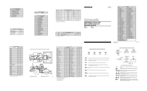
MACHINE HARNESS CONNECTOR AND COMPONENT LOCATIONS
24 15
16
4 18 19
16
15
25 21 12 26
21
1
20
19 12 22
14
3
17
13
18
22
B
6 7
11
C
9
D
11
14 20 10
2
2
6
E
3 17
23
10
7 9
Forward Horn
A
4
8
Converter - Voltage
8
5
1
5
6
13
Component
B-2,F-2
6
Switch - A/C Refrigerant
E-15
19
Fuses (10A)
B-5
A
Switch - Backup Alarm
C-8
23
Gauge - Converter Temp
E-6
B
Switch - Blower
D-6
C
Gauge - Coolant Temp
E-6
B
Switch - Cab Flood Lamp
E-6
B
Gauge - Hydraulic Temp
E-6
B
Switch - Converter
D-8
11
Lamp - Action
E-5
B
Switch - Coolant Flow
F-12
15
CONN 26
B-8
D
Lamp - Check Engine
E-5
B
Switch - Disconnect
D-13
3
CONN 27
C-8
10
Lamp - Throttle Lock Indicator
C-3
B
Switch - Eng Test/Diagnostic
C-6
A
CONN 28
F-9
C
Lighter - Cigar
C-6
A
Switch - Engine Oil Press
B-12
10
CONN 29
E-10
6
CONN 30 Starting and Charging System Diagnostic Connector
Meter - Service
F-5
B
Switch - Forward Horn
D-5
E
A-9
D
Monitor - Operator
B-6
A
Switch - Front Wiper
D-5
B
Motor - A/C Condenser
E-9
C
Switch - Fuel
F-7
24
Motor - Blower
D-6
C
Switch - Ground Level Shutdown
D-14
3
Motor - Floor Heater
A-4
E
Switch - Heater
A-4
A
Motor - Front Washer
F-6
7
Switch - Hydraulic
A-7
13
Motor - Front Wiper
D-5
8
Switch - Key Start
D-5
A
Motor - Rear Washer
F-6
7
Switch - Low Brake Press
F-8
25
Motor - Rear Wiper
F-6
9
Switch - Park Brake
F-7
25
Motor - Starter
D-8
10
Switch - Rear Wiper
D-5
B
Receptacle - Aux Start
D-14
3
Switch - RH Service Brake
C-3
17
Relay - A/C Condenser Motor
B-9
D
Switch - Running Lamp
F-6
B
Relay - Main
A-9
D
Switch - Start Aid
C-6
A
Relay - Start
A-9
D
Switch - Stop Lamp
F-8
25
C
CONN 31 Service Tool Diagnostic Connector
A-10
D
CONN 32
C-10
11
CONN 33
C-12
11
CONN 34
A-11
D
CONN 35
D-11
12
CONN 36
E-11
13
CONN 37
E-12
14
CONN 38
D-12
15
CONN 39
F-12
16
CONN 40
A-12
17
CONN 41
A-12
18
CONN 42 Timing Cal Connector
B-13
19
CONN 43
C-13
20
CONN 44
F-14
14
Relay - Start Aid
B-10
D
Switch - Thermostat
D-6
C
CONN 45
B-15
18
Resistor - Blower Motor
D-6
C
Switch - Throttle Lock On/OFF
C-3
B
CONN 46
B-15
17
Resistor - Floor Heater Motor
A-4
E
Switch - Throttle Lock Resume/Accel
B-3
B
CONN 47
C-15
21
CONN 48
C-15
22
Sender - Converter
E-8
11
Switch - Throttle Lock Set/Decel
B-3
B
Sender - Coolant
D-8
12
Switch - Transmission
D-8
26
Sender - Hydraulic
A-1
13
Switch - Transmission Filter
D-8
26
Sensor - Atmospheric Press
E-13
14
Switch - Transmission Neutral
C-8
23
Sensor - Backup Cam S/T
F-13
14
Valve - Injection Actuation Control
F-13
14
The connectors shown in this chart are for harness to harness connectors. Connectors that join a harness to a component are generally located at or near the component. See the Component Location Chart.
9
19
22
16
19
15 12
1 21
3
18
22
20
4 15
16
14 14
21
12
A
10 11
5
B
5
6
17
E
1
6
7
9
11 10
7
8
25
20 13
2 18
D
26
8
23
2
13 24
4 3
17
White callouts are for components, see Component Location chart.
Black callouts are for harness connectors, see Connectorsss Location chart.
D48556
Machine locations are repeated for components located close together. A = Components located in right instrument panel. B = Components located in left instrument panel. C = Components located in cab overhead. D = Components located on relay panel. E = Components located on cab floor.
Harness And Wire Electrical Schematic Symbols
Electrical Schematic Symbols And Definitions
A
AA
2
T
Pressure Symbol
Temperature Symbol
Typical representation of a Deutsch connector. The plug contains all sockets and the receptacle contains all pins.
Receptacle
Plug
Level Symbol
Flow Symbol
1 2
1 2
1
Typical representation of a Sure-Seal connector. The plugand receptacle contain both pins and sockets.
Pin or Socket Number Wire, Cable, or Harness Assembly Identification Single Wire Connector
Normally open switch that will close with an increase of a specific condition (temp-press-etc.).
C
A
A 325-PK-14
Normally open switch that is closed due to an applied condition, and will open again with a specific decrease in that condition.
Pin
AA 1
Normally closed switch that will open with an increase of a specific condition.
200-BK-14
Circuit Number Identification
Normally closed switch that is open due to an applied condition, and will close again with a specific decrease in that condition.
Wire Gauge
Electrical Schematic Symbols And Definitions FUSE - A component in an electrical circuit that will open the circuit if too much current flows through it.
The circle indicates that the component has screw terminals and a wire can be disconnected from it.
REED SWITCH - A switch whose contacts are controlled by a magnet. A magnet closes the contacts of a normally open reed switch; it opens the contacts of a normally closed reed switch.
No circle indicates that the wire cannot be disconnected from the component. T
This indicates that the component does not have a wire connected to ground. It is grounded by being fastened to the machine.
9X-1123 325-PK-14
Wire Color
Socket
2
This indicates that the component has a wire connected to it that is connected to ground.
Component Part Number
SENDER - A component that is used with a temperature or pressure gauge. The sender measures the temperature or pressure. Its resistance changes to give an indication to the gauge of the temperature or pressure. RELAY (Magnetic Switch) - A relay is an electrical component that is activated by electricity. It has a coil that makes an electromagnet when current flows through it. The electromagnet can open or close the switch part of the relay. CIRCUIT BREAKER (C/B) - A component in an electrical circuit that will open the circuit if too much current flows through it. This does not destroy the circuit breaker and it can be reset to become part of the circuit again. SOLENOID - A solenoid is an electrical component that is activated by electricity. It has a coil that makes an electromagnet when current flows through it. The electromagnet can open or close a valve or move a piece of metal that can do work. MAGNETIC LATCH SOLENOID - A magnetic latch solenoid is an electrical component that is activated by electricity and held latch by a permanent magnet. It has two coils (latch and unlatch) that make electromagnet when current flows through them. It also has an internal switch that places the latch coil circuit open at the time the coil latches.