Component Alarm - Action (EMS)
Schematic Location C-2
Component Location Machine Location 1
Connector
Component Solenoid - Down Shift
Schematic Location A-13
Machine Location 26
37 Contacts
25 Contacts
Alarm - Backup
B-15
2
Solenoid - Engine Shutdown
A-3
27
Alternator
A-3
3
Solenoid - Fan Clutch
A-5
20
Batteries
A-7
4
Solenoid - Lockup
A-13
28
Breakers
C-5, C-6, D-5,D-6 C-3
Solenoid - Proportional
A-14
24
5
Solenoid - Start Aid
A-4
29
Solenoid - Up Shift
A-14
26
Speedometer
F-2
A
Switch - A/C Press (Fan Clutch)
A-5
25
Control - Engine Shutdown
A
Control - Neutral/Start
F-15
6C
Control - Supplemental Steering
E-1
7
D-15
B
Control - Traction Aid Control - Transmission
E-13
B
Distributor - Transmission Speed
E-15
8C
Switch - Backup Alarm
D-11
30
Switch - Blower
E-11
16
Dryer - Air
A-8
9
Switch - Body Raise (Trans)
D-13
B
Flasher
E-5
A
Switch - Brake Master Cylinder Overstroke
A-10
31
Fuse - Supplemental Steering Lamp
A-8
Fuses
D-6
Gauge - Air Press
D3
Gauge - Brake Oil Temp Gauge - Coolant Temp Ground - Cab/Frame Ground - Frame Ground - Cab Lamp - Action (EMS) Lamp - Brake Retarder
29
32
D-3
A
F-2
A
Switch - Brake System Air Press (EMS)
C-15
33C
F-3
A
Switch - Converter/Retarder Temp (EMS)
A-9
34
32
C-11
10
Switch - Disconnect
A-6
4
11
B-9
10
Switch - Engine Coolant Flow (EMS)
A-3
35
F-2
A
Switch - Engine Oil Press (EMS)
A-4 A-3
25 3
F-15
Switch - Engine Coolant Temp (Start Aid)
34
18
20
41
14
D
28
21
2 13
10
24
16 31
30
D
22
3
8
Lamp - Engine Overspeed Warning (Not Used)
F-2
A
Switch - Fuel Press (EMS)
B-3
36
Lamp - Supplemental Steering
E-2
A
Switch - Key Start
F-3
A
Meter - Service
E-13
B
Switch - Operator Monitor Test
D-3
A
Module - Stop/Tail Lamp
B-14
12
Switch - Parking Brake Press (EMS)
C-15
37C
Monitor - Operator (EMS)
D-1
A
Switch - Refrigerant Press (AC)
B-7
38
Motor - Brake Retract
A-11
13
Switch - Running Lamp
E-3
A
Motor - Starting
A-6
14
Switch - Secondary Brake Press (Trans)
E-15
37C
Motor - Supplemental Steering
A-7
15
Switch - Service Brake Press (Tractn)
E-15
39C
Motors - Blower
E-10
16
Switch - Service Brake Press (Trans)
E-15
40C
Pickup - Engine Speed (Tach)
A-4
17
Switch - Service Clear (Trans)
E-13
B
Relay - Brake Retract
C-6
A
Switch - Service Set (Trans)
F-13
B
Relay - Main Power
D-6
A
Switch - Shift Lever
D-11
30
5
Relay - Starter
A-6
10
Switch - Start Aid
D-3
A
15
Relay - Supplemental Steering Motor
A-7
10
Switch - Stop Lamp Press (Module)
F-15
40C
Resistor - Blower Speed
E-10
16
Switch - Supplemental Steering
E-3
A
19 20
Resistor - Starter/Diagnostic Conn
A-6
14
Switch - Steering Flow
A-8
41
Sender - Brake Oil Temp (Gauge)
A-9
18
Switch - Thermostat
E-11
16
Sender - Coolant Temp (Gauge)
A-3
19
Switch - Traction Aid Test
D-3
A
Sensor - Fan Clutch
A5
20
Switch - Transmission
A-13
26
Sensor - Transmission Speed
A-13
21
Switch - Transmission Filter Press (EMS)
A-9
42
Sensor - Wheel Speed (LH)
B-15
22
Switch - Transmission Oil Temp (EMS)
A-9
42
Sensor - Wheel Speed (RH)
A-15
23
Switch - Turn Signal
D-5
A
Solenoid - 4 Way
A-14
24
Tachograph
F-12
B
A-3 25 Solenoid - Air Conditioner Clutch Machine locations are repeated for components located close together. A = Components in dash area. B = Components behind operator’s seat. C = Components in rear compartment.
Tachometer
F-3
A
8 10 6
12
17
11
40
18
39
33
A-715546 G8X1249
E-3
A-715546 L-715544
E-14
L-715544 Transmission Control
E-13
C
14 A C
B
29 38
16
30
7 32
4 4
9 Contacts
9
27 36
25 21
20
19
3 35
9
15
17 14
10
28 34
21
41
26 7
13 31
42 13 16
24
12
23
8 Contacts
Part No. 9G1950
Component Description
6T2217
Resistor - Starter/Diagnostic Conn
9G9988
Solenoid - 4 Way
8T8813 7X1120
Overall 2.0 ± .1; Tap 1.0 ± .05
Solenoid - A/C Clutch
A-715546 G-8X1249
P-8W8484 Supplemental Steering Control
E-2
A-7I5546 Not Used
E-7
C
A-7I5546 P-8W8484
E-8
A
A-7I5546 Q-7I5649
A
A-7I5546 Q-7I5649
E-5
V-8X8728 X-8X8727
A-14
Part No.
Function
C-3
A-715546 Not Used
C-10 D-5
15
A-715546 T-715825
D-4
E-715822 J-8W9717
B-14
12 C
P-8W8484 Engine Overspeed Monitor
17 C
A7l5546 M-8W8471
D-4
18 C
A-715546 N-7X1784
E-10
A-715546 R-714854
D-15
*
17 C 19 20
A-5
P-8W8484 ZZ-8X1482
D-9
T-715825 TT-715823
B-1
U-715824 U-715823
*
*
B-14
H-715819 MM-1028644
L-715544 Body Raise Switch
22 C
B-1
E-715822 Stop/Tail Lamp Module
L-715544 Actual Gear Indicator
3E2035 3E7868
B-5 D-10 D-13
L-715544 LL-2A7073
F-14
V-8X8728 4 Way Solenoid
A-14
E-5
Form Number
Contact Position
Normally Closed
Brake Retarder Air Pressure
60 kPa (8.5 psi)
28± 15 kPa (4.0 ± 2.0 psi)
Normally Open
210 ± 70 kPa (30 ± 10 psi)
-
Normally Open
552 ± 35 kPa (80 ± 5 psi)
93 ± 20.8 kPa (13.5 ± 3.0 psi)
68.9 ± 20.8 kPa (10.0 ± 3.0 psi)
Normally Open
Brake Oil Temp (EMS) Converter/Retarder Temp (EMS)
123.9 ± 2.8°C (255 ± 9°F)
112.8°C MIN (235°F MIN)
Normally Closed
7N9785
Engine Coolant Temp (EMS)
107.2 ± 2.8°C (225 ± 5°F)
91.0°C MIN (196°F MIN)
Normally Closed
8N1693
Engine Coolant Temp (Start Aid)
37.8 ± 2.8°C (100 ± 5°F)
26.7°C MIN (80°F MIN)
Normally Closed
8T9792
Brake System Air Press (EMS)
517 ± 35 kPa (75.0 ± 5.0 psi)
448 ± 35 kPa (65.0 ± 5.0 psi)
9G3341
Transmission Oil Temp (EMS)
51.7 ± 2.8°C (125 ± 5°F)
43.0°C MIN (110°F MIN)
Normally Closed
9W3187
Fuel Press (EMS)
93± 21 kPa (13.5 ± 3.0 psi)
69 ± 21 kPa (10.0 ± 3.0 psi)
Normally Closed
4 grams (.14 oz)
1.5 grams (.05 oz)
Normally Open
362 ± 29 mN (45.6 mm ID point) (1.3 ± .1 oz, 1.8 in ID point)
303 mN MIN (1.1 oz MIN)
Normally Open
6.0
Related Electrical Service Manuals
Deactuate
55 ± 20 kPa (8.0 ± 3.0 psi)
Solenoid - Start Aid
¹ At room temperature unless otherwise noted.
Actuate
656 ± 35 kPa (95 ± 5 psi)
3T3195
Parking Brake Air Press (EMS)
9X1159
Steering Flow
9X3040
Engine Coolant Flow (EMS)
Wire Color
101
RD
102
Wire Description Wire Number
Wire Color
BAT
513
OR
A/C COMPRESSOR/REFRIGERANT PRESS SW
BU
HD LMP
515
GY
BLOWER MOTOR (HI)
103
YL
AUX CKT
516
GN
BLOWER MOTOR (MEDIUM)
105
BR
KEY SW
517
BU
BLOWER MOTOR (LO)
107
WH
ENG SHUT - DOWN FIRE SUPPR
521
YL
A/C SW TO REFRIGERANT SW
109
OR
ALT OUTPUT (+) TERM
522
WH
A/C CLUTCH TO THERMOSTAT SW
112
PU
MAIN POWER RELAY OUTPUT
537
GN
TURN SIGNAL SW TO FLASHER
113
OR
CPR MON PANEL B+ SWITCHED
539
BU
TURN SIGNAL INDICATOR BASIC/RIGHT
121
YL
BACKUP ALARM TO LAMP
540
WH
TURN SIGNAL INDICATOR LEFT
122
BU
AUX CKT
A510
OR
A/C PRESSURE CUT OUT SW SIGNAL 1
123
WH
AUX CKT
124
GN
A/C
602
WH
DOME LAMP
126
PK
XMSN CONT
604
OR
STOP LAMP
132
PK
AETACONT
605
YL
TURN LAMP - LEFT
136
GN
SUPPLSTER
606
GY
TURN LAMP - RIGHT
137
OR
SUPPL STER MOTOR FUSE
610
OR
HEAD LAMP BASIC
138
GN
AUTO LUBE PUMP TO PAYLOAD MON
611
PU
HEAD LAMP HI
139
OR
AUX CKT
614
PU
PARK/TAIL/DASH LAMP
173
YL
AUX CKT
619
GN
HEAD LAMP LO
192
GN
SUPPL STER BKR TO RELAY
639
WH
LEFT HAND STOP/TAiL LAMP
640
GN
RIGHT HAND STOP/TAiL LAMP
Description Power Circuits
Normally Open
Contacts 1 - 3 (NC.) Contacts 1 - 2 (NO.)
SENR5652 April 1993
Description Accessory Circuits
Lighting Circuits
Control Circuits
200
BK
MAIN CHASSIS
201
BK
OPR MON PANEL
700
PK
AETA TEST SW
202
BK
XMSN CONT
703
BU
XMSN UP SOL
203
BK
CHASSIS DIAGNOSTIC
704
GY
XMSN DOWN SOL
207
BK
STARTER DIAGNOSTIC
705
PK
XMSN LOCKUP CLUTCH SOL BASIC
209
BK
ARE SUPPR GROUND
706
BR
XMSN RETARDER SW
212
BK
AETA CODING PIN 16
707
PU
XMSN BED RAISE SW
213
BK
AETA CODING PIN 17
709
OR
SENSOR POWER SUPPLY
215
BK
AETA CODING PIN 19
710
GN
XMSN SPEED PICKUP SIGNAL
216
BK
AETA CODING PIN 20
711
BR
XMSN LEVER CODE 1
217
BK
XMSN ID CODE 2
712
WH
XMSN LEVER CODE 2
218
BK
XMSN ID CODE 1
713
OR
XMSN LEVER CODE 3
219
BK
XMSN ID CODE 0
714
YL
XMSN LEVER CODE 4
227
BK
XMSN ID CODE 3
715
GN
XMSN LEVER CODE 5
231
BK
XMSN SW
716
BU
XMSN LEVER CODE 6
237
BK
KBI ETHER CONT GROUND
720
PU
XMSN BRAKE SW
Basic Machine Circuits
721
BR
XMSN GEAR CODE 1
STARTER NO 1 SOL
722
WH
XMSN GEAR CODE 2
OR
XMSN GEAR CODE 3
301
BU
302
OR
STARTER NO 1 RESISTOR TO DIAGNOSTIC
723
304
WH
STARTER RELAY NO 1 OUTPUT
724
YL
XMSN GEAR CODE 4
306
GN
STARTER RELAY COIL TO NEUT START SW
725
GN
XMSN GEAR CODE 5
307
OR
KEY SW TO NEUT START
726
BU
XMSN GEAR CODE 6
308
YL
MAIN POWER RELAY COIL
727
GN
SUPPL STER MOTOR RELAY
310
PU
START AiD SW TO START AiD SOL
728
BU
SUPPL STER CONT SW
311
WH
START AiD SOL TO TEMP SW
733
BR
SWITCHING GEAR CODE 1 FRONT
313
GY
STARTER NO 2 RESISTOR TO DIAGNOSTIC
734
WH
SWITCHING GEAR CODE 2 FRONT
314
PU
STARTER RELAY NO.2 OUTPUT
735
OR
SWITCHING GEAR CODE 3 FRONT
321
BR
BCKP AlARM LAMP TRAVEL ALARM
736
YL
SWITCHING GEAR CODE 4 FRONT
326
PU
KEY SW "C" TERM.
737
GN
SWITCHING GEAR CODE 5 FRONT
327
PK
SHUTDOWN SOL
767
WH
AETA PICKUP POWER
768
OR
AETA PICKUP XMSN
Monitoring Circuits
Off Machine Switch Specification
Transmission Filter Bypass Press (EMS)
Wire Number
Ground Circuits
H-715819 Fan Clutch Sensor
A 4 Contacts
F-1
80 kPa (12.0 psi)
3E2034
7N7259
SENR2947
P-8W8484 Engine Shutdown Control
Service Brake Air Pressure (Tractn) Service Brake Air Pressure (Trans)
24.9
7N7854
SENR3860
D-10
Normally Open
16.0
Starting Motor (3T8967)
L-715544 Actual Gear Indicator
530 ± 40 kPa (77.0 ± 6.0 psi)
Solenoid - Proportional
Starting And Charging Systems
C-10
640 kPa (92.0 psi)
3T0062
SENR5618
D-2A6782 P-8W8484
Secondary Brake Air Pressure (Trans)
Engine Oil Pressure (EMS)
Electronic Programmable Transmission Control II
E-15
Normally Open
6T7663
SENR3889
A-715546 Transmission Speed Distributor
5 kPa MIN (0.5 psi MIN)
24.0
Electronic Neutral Start Control
E-9
A
14 C
E-7
A-715546 P-8W8484
A-715546 S-6G9462
16
5 Contacts
Schematic Location
45 kPa MAX (6.5 psi MAX)
Solenoid - Fan Clutch
SENR2945
6 Contacts
F-3
F-15
101-0329
Electronic Monitoring System
14 C
21
3E2033
3.70 ± .37
SENR2986
*
C10
Solenoid - Engine Shutdown
Automatic Electronic Traction Aid
A
C-8W9720 P-8W8484
9X1413
SENR2082 SENR4130
9
*
150 ± 7.5
33.7
Alternator (1005047): Consist No. 1005046 Consist No. 1005045
7 Contacts
E-8
Stop Lamp Press (Module)
14.4 ± 0.6
Title
*
A-715546 P-8W8484
2M9346
Solenoids - Down Shift, Up Shift, Lockup
C
Harness And/Or Components
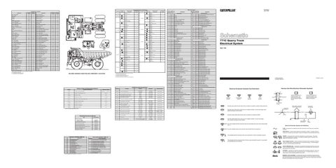
Machine locations are repeated for connectors located close together. * = Connector is located at the component. A = Connector is located behind the dash. B = Connector is located behind the operator’s seat. C Connector is located in the rear compartment. D = Connector is located at the right side wall of the rear compartment.
Resistance (Ohms)¹
Resistor - Blower Motor Speed
A-13
P-8W8484 Neutral/Start Control
C
13
Resistor, Sender and Solenoid Specifications
Z-7T3418 Transmission Switch
E-12
C37283P3
MACHINE HARNESS CONECTOR AND COMPONENT LOCATIONS
A-13
B
12 C 8
V-715821 Z-7T3418
L-715544 Diagnostic Connector (Transmission Control)
11 22
D-11
F-8X1250 P-8W8484
2
18
VV-8W6419 Shift Lever Switch
Machine Location
8
E-3
A
10
Connector
D-2
A
9 11
C-13
A
8
A
L-715544 Y-715821
A-715546 G-8X1249
*
1
D-12
C-14
7
D
A-715546 Diagnostic Connector (Starting And Charging)
R-714854 V-8X8728
D
2
C
C-12
D-10
*
1
A-715546 J-8W9717
L-715544 VV-8W6419
5
37
C-11
4
*
3
22
6
A-715546 H-715819
D-15
10 Contacts
19
D-13
*
6
3
L-715544 Transmission Control
R-714854 Traction Aid
5
7
Schematic Location
P-8W8484 Operator Monitor
B
4
Harness Connector Location Chart
Harness And/Or Components
*
14 Contacts
16
1
3
12
18
9
9
A
15
17
19
19 5
26
20 Contacts
13
42
7
15
27
38
Switch - Brake Retract
A
35 36
21
Switch - Brake Retarder Press
F-2
23
20
A
B-3
D
B
A
Switch - Engine Coolant Temp (EMS)
1 2
A-9
11C
*
4
Switch - Brake Oil Temp (EMS)
E-12
10
Machine Location
403
GN
ALTERNATOR (R) TERM.
769
BU
WHEEL SPEED PICKUP LEFT
405
GY
OPR MON OIL PRESS. (LO SETTING)
770
GN
WHEEL SPEED PICKUP RIGHT
406
PU
OPR MON COOLANT TEMP
772
BR
AETA RETARDER SW
407
PK
OPR MON CONVERTER/RETARDER OIL TEMP
773
GY
AETA SERVOVALVE
408
WH
OPR MON SYSTEM AIR PRESS
774
YL
AETA SOL - LEFT
409
OR
OPR MON NEUT
775
BR
AETA SOL - RIGHT
410
WH
OPR MON ACTION ALARM
777
PU
BRAKE RELEASE MOTOR
411
PK
OPR MON ACTION LAMP
794
YL
PAYLOAD MON XMSN SPEED
412
BU
OPR MON COOLANT FLOW
891
BU
NEUT START CONT TO PAYLOAD MON SYSTEM
413
BR
OPR MON FUEL PRESS.
892
BR
DATALINK(-)
415
GN
OPR MON TEST SW
893
GN
DATA LINK (+)
417
GY
PRIMARY STER SW
918
OR
ENG OVERSPEED LIGHT AND HORN
419
YL
OPR MON PARKING BRAKE
919
GN
ENG OVERSPEED TEST SW
426
BR
OPR MON POWER TRAIN OIL FILTER
930
BR
BRAKE RETRACT SW TO RELAY COIL
437
BR
OPR MON FUEL LEVEL TO FUEL FILTER JUMPER
943
OR
TEHC SWING - JOY 2
441
OR
ENG COOLANT TEMP GAGE
A983
BU
ENG THROTTLE CONT - SIGNAL
446
PU
BRAKE OIL TEMP GAGE
B770
YL
FAN CONTROL SOLENOID POSITIVE
449
BU
SPDOM SENDER (SIGNAL NO. 1)
B771
BR
FAN CONTROL SOLENOID RETURN
450
YL
TACH SENDER (+)
B943
PK
START AID CONT LAMP 1 OUTPUT
454
GN
RETARDER INDICATOR LAMP
B946
OR
START AID CONT MANUAL INPUT
462
YL
SUPPL STER MOTOR INDICATOR
B954
YL
START AID coNT TEST SW INPUT
470
PU
CANE SW NEUT
B998
BU
START AID CONT LAMP 2 OUTPUT
472
OR
PARKING BRAKE SW TO OVERSTROKE SW
D966
GY
AFTERCODLER COOLANT LEVEL
481
GN
CONVERTER TEMP SW TO BRAKE OIL TEMP SW
D983
PK
SEVERE SHIFT LIMIT CONT RACK SOL
D996
PU
TRANSMISSION CONT SERVICE SET
D997
YL
TRANSMISSION CONT SERVICE CLEAR
771C Quarry Truck Electrical System 3BJ1-199
Printed in U.S.A.
© 1993 Caterpillar All Rights Reserved
Harness And Wire Electrical Schematic Symbols
Electrical Schematic Symbols And Definitions A
AA
T
Pressure Symbol
Temperature Symbol
Level Symbol
Flow Symbol
Typical representation of a Deutsch connector. The plug contains all sockets and the receptacle contains all pins.
Receptacle
Plug
1 2
1 2
1
2
Typical representation of a Sure-Seal connector. The plugand receptacle contain both pins and sockets.
Pin or Socket Number
Normally open switch that will close with an increase of a specific condition (temp-press-etc.).
Wire, Cable, or Harness Assembly Identification
Component Part Number
Single Wire Connector
Normally open switch that is closed due to an applied condition, and will open again with a specific decrease in that condition.
C
A
A 325-PK-14
Pin
Normally closed switch that will open with an increase of a specific condition.
AA 1
325-PK-14
Wire Color
Socket
2
Normally closed switch that is open due to an applied condition, and will close again with a specific decrease in that condition.
9X-1123
200-BK-14
Circuit Number Identification
The circle indicates that the component has screw terminals and a wire can be disconnected from it.
Wire Gauge
Electrical Schematic Symbols And Definitions FUSE - A component in an electrical circuit that will open the circuit if too much current flows through it.
No circle indicates that the wire cannot be disconnected from the component.
REED SWITCH - A switch whose contacts are controlled by a magnet. A magnet closes the contacts of a normally open reed switch; it opens the contacts of a normally closed reed switch.
This indicates that the component has a wire connected to it that is connected to ground. CID 168 190 248 269 627 650 700 701 702 704 705 706 707 708 709
Component Identifiers (CID) List Component
Electrical System Voltage Engine RPM Sensor CAT Data Link Sensor Supply Parking Brake Switch Harness Code Transmission Gear Switch Transmission Output Speed Sensor Shift Lever Switch Service Brake Pressure Switch Body Raise Switch Body Up Switch Up Solenoid Down Solenoid Lockup Solenoid
FMI No.
Failure Mode Identifiers (FMI) List
T
Failure Description
0
Data valid but above normal operational range.
1
Data valid but below normal operational range.
2
Data erratic, intermittent, or incorrect.
3
Voltage above normal or shorted high.
4
Voltage below normal or shorted low.
5
Current below normal or open circuit.
6
Current above normal or grounded circuit.
7
Mechanical system not responding properly.
8
Abnormal frequency, pulse width, or period.
9
Abnormal update.
10
Abnormal rate of change.
11
Failure mode not identifiable.
12
Bad device or component.
13
Out of calibration.
This indicates that the component does not have a wire connected to ground. It is grounded by being fastened to the machine.
SENDER - A component that is used with a temperature or pressure gauge. The sender measures the temperature or pressure. Its resistance changes to give an indication to the gauge of the temperature or pressure. RELAY (Magnetic Switch) - A relay is an electrical component that is activated by electricity. It has a coil that makes an electromagnet when current flows through it. The electromagnet can open or close the switch part of the relay. CIRCUIT BREAKER (C/B) - A component in an electrical circuit that will open the circuit if too much current flows through it. This does not destroy the circuit breaker and it can be reset to become part of the circuit again. SOLENOID - A solenoid is an electrical component that is activated by electricity. It has a coil that makes an electromagnet when current flows through it. The electromagnet can open or close a valve or move a piece of metal that can do work.
This CID list applies to the transmission control (EPTC II).
MAGNETIC LATCH SOLENOID - A magnetic latch solenoid is an electrical component that is activated by electricity and held latch by a permanent magnet. It has two coils (latch and unlatch) that make electromagnet when current flows through them. It also has an internal switch that places the latch coil circuit open at the time the coil latches.