COMPONENT LOCATION CHART Machine Location 1
COMPONENT IDENTIFIER (CID) LIST Automatic Retarder Control (ARC)
CID No. 091 168 190 248 627 650 700 702 710 711 712 713 714 715
Component Accelerator Position Signal¹ Electrical System Voltage Engine RPM Sensor CAT Data Link Parking Brake Signal¹ Harness Code Actual Gear Signal ¹ Selected Gear Signal¹ ARC Supply Solenoid ARC Control Solenoid Retarder Lamp ARC On/Off Switch Auto Retarder Pressure Switch Retarder Pressure Switch
¹ Signal recieves by ARC on the CAT data link.
Schematic Location
Component
Alarm - Action (EMS)
C-2
27C
Solenoid - ARC Supply Valve
C-9
Alarm - Backup
B-15
A
Alarm - Engine Overspeed
F-1
28 29
Solenoid- Down Shift Solenoid - Engine Fan (Fan Clutch)
A-14 A-5
3
Alternator
A-3
30
Solenoid - Engine Shutdown
A-3
4
Batteries
A-7 C-5, C-6, D-5, D-6 C-8
16
Solenoid - Lockup
A-13
25
Solenoid - Proportional
A-14
31
Solenoid - Start Aid
A-5
A
Breakers
5C
Control - Auto Retarder (ARC)
6
Control - Engine Shutdown
C-3
28
Solenoid - Up Shift
A-14
7
Control - Supplemental Steering
E-1
A
Speedometer
F-2
B
Control - Traction Aid (AETA)
D-15
26
Switch - AC Pressure (Fan Clutch)
A-5
B
Control - Transmission (EPTC II)
D-13
32C
Switch - Accelerator Press (ARC)
C-9
8C
Converter - 24V/12V
C-4
A
Switch - Auto Retarder OFF/ON (ARC)
D-3
9C
Distributor - Transmission Speed
E-15
33
Switch - Backup Alarm
D-11
10
Dryer - Air
A-8
17
Switch - Blower
E-11
A
Flasher
E-5
B
Switch - Body Raise (EPTC II)
D-12
11
Fuse - Supplemental Steering Lamp
A-8
34
Switch - Brake Master Cylinder Overstroke
A-10
A
Fuses
D-6
19
Switch - Brake Oil Temp (EMS)
A-9
A
Gauge - Air Press
D-3
35
Switch - Brake Retarder Press
F-15
A
Gauge - Brake Oil Temp
F-2
36C
Switch - Brake System Air Press (EMS)
C-15
A
COMPONENT IDENTIFIER (CID) LIST
Machine Location
2
Gauge - Coolant Temp
F-3
37
Switch - Converter/Retarder Temp
A-9
Ground - Cab
E-12
4
Switch - Disconnect
A-6
13
Ground - Cab/Frame
C-11
A
Switch - EMS/AETA Test
D-3
13
Ground - Frame
B-9
38
Switch - Engine Coolant Flow (EMS)
A-4
A
Indicator - Transmission Gear
D-10
3
Switch - Engine Coolant Temp (EMS)
B-4
A
Lamp - Action (EMS)
F-2
39
Switch - Engine Coolant Temp (Start Aid)
A-5
A
Lamp - Brake Retarder
F-2
29
Switch - Engine Oil Press (EMS)
A-4
A
Lamp - Engine Overspeed Warning
F-2
40
Switch - Fuel Press (EMS)
B-4
A
Lamp - Retarder (ARC)
C-9
A
Switch - Key Start
F-3
A
Lamp - Supplemental Steering
E-2
35
Switch - Manual Retarder Press (ARC)
C-9
12C
Electronic Programmable Transmission Control II (EPTC II) (MID No. 027) CID No. Component 168 Electrical System Voltage 190 Engine RPM Sensor 248 CAT Data Link 269 Sensor Supply 627 Parking Brake Switch 650 Harness Code 672 Torque Converter Output Speed Sensor 700 Transmission Gear Switch 701 Transmission Output Speed Sensor 702 Shift Lever Switch 704 Service Brake Pressure Switch 705 Body Raise Switch 706 Body Up Switch 707 Up Solenoid 708 Down Solenoid 709 Lockup Solenoid
Component
Schematic Location
B
Meter - Service
E-13
41C
Switch - Parking Brake Press (EMS)
C-15
14
Module - Stop/Tail Lamp
B-14
42
Switch - Refrigerant Press (AC)
B-7
Switch - Retarder Press (ARC)
C-9
Switch - Running Lamp
E-3
6
Monitor - Engine Overspeed
E-1
27C
A
Monitor - Operator (EMS)
D-1
A
15
Motor - Starting
A-6
41C
Switch - Secondary Brake Press (EPTC II)
E-15
16
Motor - Supplemental Steering
A-7
43C
Switch - Service Brake Press (AETA)
E-15
17
Motors - Blower
E-10
43C
Switch - Service Brake Press (EPTC II)
E-15
18
Pickup - Engine Speed (Tachometer)
A-5
5C
Switch - Service Clear (ARC)
C-8
6
Relay - Main Power
D-6
B
Switch - Service Clear (EPTC II)
E-13
11
Relay -Starter
A-6
5C
Switch - Service Set (ARC)
C-8
11
Relay - Supplemental Steering Motor
A-7
B
Switch - Service Set (EPTC II)
F-13
17
Resistor - Blower Speed
E-10
33
Switch - Shift Lever
D-11
15
Resistor - Start/Charge Diagnostic Conn
A-6
A
Switch - Start Aid
D-3
19
Sender - Brake Oil Temp (Gauge)
A-9
10
Switch - Steering Flow
A-8
20
Sender - Coolant Temp (Gauge)
A-4
43C
Switch - Stop Lamp Press (Module)
F-15
OFF MACHINE SWITCH SPECIFICATIONS Part No. 2M-9346
Function Stop Lamp Pressure (Module)
Actuate 45 kPa MAX (6.5 psi MAX)
Deactuate 5 kPa MIN (0.5 psi MIN)
Contact Position Normally Open
3E-2033
Secondary Brake Air Pressure (EPTC II) Parking Brake Pressure (EMS)
640 kPa (92.0 psi)
530 ± 40 kPa (77.0± 6.0 psi)
Normally Open
3E-2034
Service Brake Air Pressure (AETA) Service Brake Air Pressure (EPTC II)
80 kPa (12.0 psi)
55± 20 kPa (8.0 ± 3.0 psi)
Normally Closed
3E-2035
Brake Retarder Air Pressure Manual Retarder Pressure (ARC)
60 kPa (8.5 psi)
28± 15 kPa (4.0 ± 2.0 psi)
Normally Open
3E-7868
Transmission Filter Bypass Pressure (EMS)
210 ± 70 kPa (30 ± 10 psi)
_ --
Normally Open
6T-7663
Engine Oil Pressure (EMS)
93 ± 20.8 kPa (13.5± 3.0 psi)
68.9 ± 20.8 kPa (10.0 ± 3.0 psi)
Normally Open
7N-7854
Brake Oil Temperature (EMS) Converter/Retarder Temperature (EMS)
123.9 ± 2.8°C (255 ± 9°F)
112.8°C MIN (235°F MIN)
Normally Closed
7N-9785
Converter/Retarder Temperature (EMS)
107.2± 2.8°C (225 ± 5°F)
91.0°C MIN (196°F MIN)
Normally Closed
8N-1693
Engine Coolant Temperature (Start Aid)
37.8 ± 2.8°C (100 ± 5°F)
26.7°C MIN (80°F MIN)
Normally Closed
8T-9792
Brake System Air Pressure (EMS)
517 ± 35 kPa (75.0± 5.0 psi)
448 ± 35 kPa (65.0± 5.0 psi)
1-3, Normally Closed 1-2, Normally Open
9G-3341
Transmission Oil Temperature (EMS)
51.7 ± 2.8°C (125 ± 5°F)
43.0°C MIN (110°F MIN)
Normally Closed
9W-0263
Retarder Pressure (ARC)
48.2± 13.8 kPa (7.0 ± 2.0 psi)
24.1 kPa MIN (3.5 psi MIN)
Normally Closed
9W-3187
Fuel Pressure (EMS)
93 ± 21 kPa (13.5 ± 3.0 psi)
69 ± 21 kPa (10.0 ± 3.0 psi)
Normally Closed
9X-3040
Engine Coolant Flow (EMS)
303 mN MIN (1.1 oz MIN)
Normally Open
101-0912
AC Pressure (Fan Clutch)
1600 ± 135 kPa (230 ± 20 psi)
1275 ± 100 kPa (185± 15 psi)
Normally Open
107-0615
Accelerator Pressure (ARC)
48± 14 kPa (7.0 ± 2.0 psi)
24 kPa MIN (3.5 psi MIN)
Normally Closed
109-4215
Steering Flow
4 grams (.14 oz)
1.5 grams (.05 oz)
Normally Open
114-5334
Refrigerant Pressure (AC)
275 to 1750 kPa 1 (40 to 255 psi)
_ --
Normally Open 2
362 ± 29 mN (45.6 mm ID point) (1.3± .1 OZ, 1.8 in ID point)
Component
RESISTOR AND SOLENOID SPECIFICATIONS Part No.
Sensor - Body Up (EPTC II)
A-13
A
Switch - Supplemental Steering
E-3
Sensor - Engine Coolant Temp (Fan Clutch)
A-5
17
Switch - Thermostat
E-11
Resistor - Starter/Diagnostic Conn
6T-2217
150± 7.5
22
Sensor - Transmission Speed
A-13
28
Switch - Transmission
A-13
Solenoid - 4 Way
9G-9988
24.9
23
Sensor - Wheel Speed (LH)
B-15
44
Switch - Transmission Filter Press (EMS)
A-9
Solenoid - A/C Clutch
8T-8813
14.4 ± 0.6
24
Sensor - Wheel Speed (RH)
A-15
44
Switch - Transmission Oil Temp (EMS)
A-9
Solenoids - ARC Control Valve, ARC Supply Valve
9X-7876 (from 3E-8691)
29.8± 1.5
25
Solenoid - 4 Way
A-14
A
Switch - Turn Signal
D-5
Solenoids - Down Shift, Up Shift, Lockup
7X-1120
33.7
26
Solenoid - Air Conditioner Clutch
B-3
B
Tachograph
F-12
Solenoid - ARC Control Valve
C-9
A
Tachometer
F-3
Solenoid - Engine Fan
101-0329
62.0±: 6.2
Solenoid - Engine Shutdown
9X-1413
3.70 ± .37
Solenoid - Proportional
3T-0062
16.0
Solenoid - Start Aid
7N-7259
6.0
B = Components located behind operator's seat.
769C: 1X6600-UP
771C: 3BJ200-UP
9G-1950
Resistance (Ohms) 1
21
A = Components located in dash area.
768C: 2X400-UP
² Contact postion at the contacts of the harness connector.
14
27C
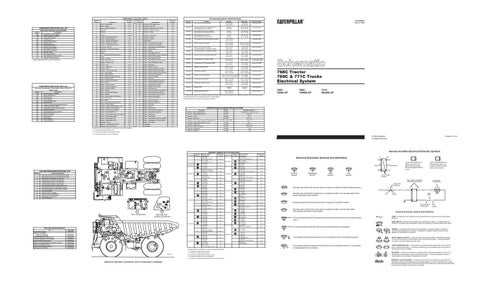
768C Tractor 769C & 771C Trucks Electrical System
¹ A hysteresis band exists: with increasing pressure the closed condition can be maintained up to 2800 kpa (405 psi), with decreasing pressure the closed condition can be maintained down to 170 kpa (25psi).
Resistor - Blower Motor Speed
Machine locations are repeated for components located close together.
SENR6839 March 1994
Overall 2.0 ± .1; Tap 1.0 ± .05
C = Components located in rear compartment
Printed in U.S.A.
© 1994 Caterpillar All Rights Reserved
Connectors 37 Contacts
Machine Location
* *
25 Contacts
18
FMI No. 0 1 2 3 4 5 6 7 8 9 10 11 12 13
FAILURE MODE IDENTIFIER (FMI) LIST Failure Description Data valid but above normal operational range. Data valid but below normal operational range. Data erratic, intermittent, or incorrect. Voltage above normal or shorted high. Voltage below normal, or shorted low. Current below normal or open circuit. Current above normal, or grounded circuit. Mechanical system not responding properly. Abnormal frequency, pulse width, or period. Abnormal update. Abnormal rate of change. Failure mode not identifiable. Bad device or component. Out of calibration.
38 40 20 21 26 3
19 6
30
20 15
29 13 11
A
17 33 4
11
44
39
42 1
16 35 14
2 D
24
31
37 16
B
7 28
22
18
25
* 23
34
14 Contacts
10 B
7
6 C
13
8
27
21
6
41
12
5
3
32
10 Contacts
*
2
36 5 17
* 7
D
C
Rear Compartment
A
Right Side Wall Of Rear Compartment
8 C
1 11
A 9 Contacts
B
A
Actual Gear Indicator Alternator (100-5047): Consist No.100-5046 Consist No.100-5045 Automatic Electronic Traction Aid Automatic Retarder Control System Electronic Monitoring System Electronic Programmable Transmission Control II Engine Overspeed Indicator Starting And Charging Systems Starting Motor (3T-8967)
SENR2082 SENR4130 SENR2986 SENR5683 SENR2945 SENR5666 SENR4263 SENR2947 SENR3860
35 16 6 18 7 31 1914 42
* *
1
43
10
Form No. SENR4252
5 D
A
8
Title
4
A
9
RELATED SERVICE MANUALS
3 D
*
2
12
9
20 Contacts
14
19
1 D
33
4
A
17 4
9
B
13
9
26 30 40 11 39 20 21 20 18 3 29 10 38 15
16
37
*
14 44 22
7
28
34
12
25
8 C
2
15
8 Contacts
19
A 10 C
23 24
*
HARNESS CONNECTOR LOCATION CHART
Harness And/Or Components
L-109-4159 Transmission Control PP-111-0715 Auto Retarder Control A-109-4160 H-111-8137 A-109-4160 J-111-8138 Diagnostic Connector (Starting And Charging) L-109-4159 Y-111-0719 P-109-4196 Operator Monitor R-71-4854 Traction Aid L-109-4159 VV-8W-6419 R-71-4854 V-8X-8728 A-109-4160 G-109-4052 A-109-4160 G-109-4052 A-109-4160 L-109-4159 L-109-4159 Transmission Control PP-111-0715 Auto Retarder Control VV-8W-6419 Shift Lever Switch Z-7T-3418 Transmission Switch Y-111-0719 Z-7T-3418 A-109-4160 G-109-4052 A-109-4160 P-109-4196 A-109-4160 Q-109-4341 C-104-3938 P-109-4196 F-108-4529 P-109-4196 L-109-4159 Diagnostic Connector (Transmission Control) P-109-4196 Supplemental Steering Control A-109-4160 P-109-4196 A-109-4160 Q-109-4341 A-109-4160 PP-111-0715 MM-111-0714 Engine Overspeed Monitor
Schematic Machine Harness And/Or Connectors Location Location Components
C-7
8 Contacts
11 12
C-11 C-12
8 C
D-12
*
C-13
7 Contacts
*
D-15
13 C
D-10
A
C-14 E-3
9 A
D-2
6 Contacts
E-3
14 15
*
E-14
16
E-13 C-8
10 C
D-11
17 C
*
A-13 A-13
18 5 Contacts
F-3
13 C
E-8
10 C 19
E-5
9
C-10
*
E-7
20
E-12 E-2
4 Contacts
21 C
E-8
*
E-5
A
C-6
*
E-1
Machine locations are repeated for components located close together. * = Connector is located at the component.
D01108
*
D-13
A = Connector is located behind the dash. B = Connector is located behind the operator's seat. C = Connector is located in the rear compartment.
MM-111-0714 Engine Overspeed Monitor NN-106-9506 Radio (Attachment) V-8X-8728 X-8X-8727 A-109-4160 P-109-4196 A-109-4160 Transmission Speed Distributor D-104-3939 P-109-4196 L-109-4159 Transmission Gear Indicator P-109-4196 Engine Shutdown Control A-109-4160 M-111-0713 A-109-4160 S-6G-9462 A-109-4160 T-71-5825 E-104-7638 J-111-8138 NN-106-9506 Converter P-109-4196 MM-111-0714 A-109-4160 N-7X-1784 A-109-4160 R-71-4854 Coolant Temp Sensor (Fan Clutch) U-71-5824 TT-71-5823 P-109-4196 ZZ-8X-1482 PP-111-0715 RR-109-4050 T-71-5825 TT-71-5823 Y-111-0719 RR-109-4050 E-104-7638 Stop/Tail Lamp Module H-111-8137 MM-111-0714 L-109-4159 LL-2A-7073 L-109-4159 Body Raise Switch L-109-4159 Transmission Gear Indicator V-8X-8728 4 Way Solenoid
Harness And Wire Electrical Schematic Symbols Schematic Location E-1
Electrical Schematic Symbols And Definitions
A
AA
C-3 A-14 E-9 E-15 C-10
2
T
Pressure Symbol
Temperature Symbol
Typical representation of a Deutsch connector. The plug contains all sockets and the receptacle contains all pins.
Receptacle
Plug
Level Symbol
Flow Symbol
Wire, Cable, or Harness Assembly Identification
C-3
Normally open switch that will close with an increase of a specific condition (temp-press-etc.).
C
A
A
D-4
C-4
325-PK-14
Normally open switch that is closed due to an applied condition, and will open again with a specific decrease in that condition.
Pin
F-1 E-10
B-1
AA 1
Normally closed switch that will open with an increase of a specific condition.
9X-1123 325-PK-14
Wire Color
Socket
2
200-BK-14
Circuit Number Identification
D-15 A-5
Component Part Number
Single Wire Connector
D-4
B-14
Typical representation of a Sure-Seal connector. The plugand receptacle contain both pins and sockets.
Pin or Socket Number
D-10
D-5
1 2
1 2
1
Normally closed switch that is open due to an applied condition, and will close again with a specific decrease in that condition.
Wire Gauge
Electrical Schematic Symbols And Definitions
D-9 C-7 B-1
FUSE - A component in an electrical circuit that will open the circuit if too much current flows through it.
The circle indicates that the component has screw terminals and a wire can be disconnected from it.
REED SWITCH - A switch whose contacts are controlled by a magnet. A magnet closes the contacts of a normally open reed switch; it opens the contacts of a normally closed reed switch.
B-12 B-14
No circle indicates that the wire cannot be disconnected from the component.
B-5
T
SENDER - A component that is used with a temperature or pressure gauge. The sender measures the temperature or pressure. Its resistance changes to give an indication to the gauge of the temperature or pressure.
F-14 D-12
This indicates that the component has a wire connected to it that is connected to ground.
RELAY (Magnetic Switch) - A relay is an electrical component that is activated by electricity. It has a coil that makes an electromagnet when current flows through it. The electromagnet can open or close the switch part of the relay.
This indicates that the component does not have a wire connected to ground. It is grounded by being fastened to the machine.
CIRCUIT BREAKER (C/B) - A component in an electrical circuit that will open the circuit if too much current flows through it. This does not destroy the circuit breaker and it can be reset to become part of the circuit again.
D-10 A-14
SOLENOID - A solenoid is an electrical component that is activated by electricity. It has a coil that makes an electromagnet when current flows through it. The electromagnet can open or close a valve or move a piece of metal that can do work.
D = Connector is located at the right side wall of the rear compartment.
Machine Harness Connector And Component Locations
MAGNETIC LATCH SOLENOID - A magnetic latch solenoid is an electrical component that is activated by electricity and held latch by a permanent magnet. It has two coils (latch and unlatch) that make electromagnet when current flows through them. It also has an internal switch that places the latch coil circuit open at the time the coil latches.