RENR1497 April 1999
Component Location Schematic Location
Machine Location
Schematic Location
Machine Location
Actuator - Water Valve
F-5
6
Air Dryer
A-6
5
Solenoid - Air Conditioner Clutch
A-9
2
Solenoid - ASBS
A-15
Alarm - Action
E-9
1
A
Solenoid - Axle Suspension
B-12
D
Alarm - Backup Alternator
C-15
32
Solenoid - FWD Horn
C-9
24
A-8
2
Solenoid - Impl Valve Detent
A-13
15
Batteries
A-12
3
Solenoid - Start Aid
A-5
25
Breaker - Alternator
E-13
B
Solenoid - Torque Converter
C-13
10
Breaker - Blower Motor
E-13
B
Speedometer
C-4
A
Breaker - Dome, Stop, Turn Lamp
E-13
B
Switch - Air
C-9
D
Breaker - Head, Panel, Tail & Park Lamp
E-13
B
Switch - Air Pressure
C-12
26
Breaker - Key
E-13
B
Switch - A/C
F-1
2
Electronic Monitoring System (EMS)
F-10
A
Switch - Backup Alarm
F-12
C
Control Board Assembly
F-6
6
Switch - Converter
B-11
10
Flasher
F-9
E
Switch - Coolant
B-9
30
Fuse Block
F-12
B
Switch - Coolant Flow
B-14
22
Gauge - Air Pressure
C-4
A
Switch - Disconnect
A-12
2
Gauge - Converter Temp
B-5
A
Switch - Dome Lamp
F-10
E
Gauge - Coolant Temp
B-4
A
Switch - Ejector Detent
A-9
29
Gauge - Fuel
C-4
A
Switch - Ejector Detent Press
A-13
15
Ground
E-15
32
Switch - El Neu Start
F-11
A
Ground - Cab
C-2
D
Switch - EMS Test
D-3
A
Ground - Chassis
C-2
D
Switch - Engine Oil
A-9
29
Ground - Compartment
D-13
B
Switch - Engine Oil Press
A-9
29
Ground - Scraper Chassis
D-15
32
Switch - Fan Speed
F-2
A
Component
14 3 5 25 34
4
2 29
13
28
30
22
24 18
17
19
27
10
23
11
8 26
15
A
7
31 16
E
12
9
20
21
B
7
9 31
E
5
A 13
25 34
8 2
6
26
C 29
30 22 18
D
24
1
C D
6
33
32
12
21
28
B
14 4
15 10
17
19
32
33 27 23
20
11
3
1
16
Lamp - EMS Action
B-5
A
Switch - Flood Lamp
F-2
A
Meter - Tach/HR
C-5
A
Switch - Forward Horn
F-9
E
Motor - Blower
F-8
6
Switch - Front Wiper
F-5
A
Motor - Front Washer Pump
A-2
6
Switch - Front/Rear Washer
D-5
A
Motor - Front Wiper
F-8
7
Switch - Fuel
B-9
22
Motor - Fuel Pump
B-15
1
Switch - Fuel Pump
D-2
A
Motor - Rear Washer Pump
A-3
34
Switch - Head Lamp Dimmer
C-9
E
Motor - Rear Wiper
F-14
9
Switch - Headlamp
F-3
A
Motor - Starter
A-11
10
Switch - Key
E-1
A
Receptacle - Aux Start
A-10
2
Switch - Neutral
F-11
A
Relay - Fuel Pump
D-11
12
Switch - Neutral Start
F-11
A
Relay - Head Lamp
E-14
D
Switch - Panel Dimmer
E-6
A
Relay - Main
E-12
12
Switch - Parking Brake
C-9
27
Relay - Start
D-12
12
Switch - Rear Wiper
D-5
A
Relay - Suspension Axle
D-13
B
Switch - Refrigerant
C-9
2
Resistor - Blower Motor
E-8
6
Switch - Start Aid
D-3
A
Resistor - Diagnostic
B-11
10
Switch - Start Aid Temp
B-9
30
F-5
A
Switch - Steering
B-12
23
Sender - Converter
B-11
10
Switch - Stop Lamp
C-10
D
Sender - Coolant
B-9
13
Switch - Thermostat
E-8
6
Sender - Fuel Level
D-15
14
Switch - Torqe Converter
F-12
E
Sender - Tachometer
B-11
15
Switch - Turn Signal
F-8
E
Sender - Trans Output Speed
A-11
16
Resistor - Panel Dimmer
E79930
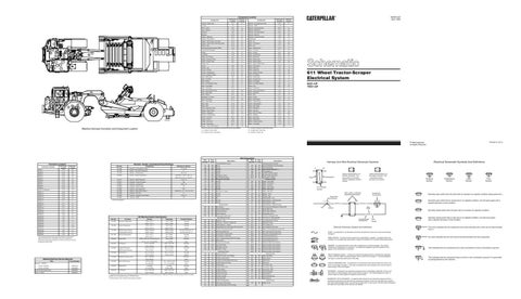
Machine Harness Connector and Component Location
Component
Machine locations are repeated for components located close together.
C = Located in operator's right hand console.
A = Located in Tractor dash.
D = Located under Tractor cab.
B = Located in cab on relay panel.
E = Located in Tractor cab.
611 Wheel Tractor-Scraper Electrical System 6SZ1-UP 7WZ1-UP
Printed in U.S.A.
© 1999 Caterpillar All Rights Reserved
Wire Description Wire Number
Connector Location¹
Machine Location
CONN 1
E-14
32
CONN 2
C-14
23
CONN 3
D-14
B
CONN 4
E-14
B
CONN 5
F-14
B
CONN 6
C-13
23
CONN 7
C-13
23
CONN 8
E-13
B
CONN 9
E-13
B
CONN 10 Diagnostic
F-12
B
CONN 11
B-12
23
CONN 12
B-12
23
CONN 13
C-12
10
CONN 14
C-12
11
CONN 15
C-11
11
CONN 16
C-11
11
CONN 17
E-11
B
CONN 18
F-11
B
CONN 19
F-11
B
CONN 20
F-11
B
CONN 21
C-10
11
CONN 22
E-9
E
CONN 23
F-8
7
Part No.
CONN 24
E-8
6
7N-9560
CONN 25
E-7
A
CONN 26
A-6
18
CONN 27
A-6
18
CONN 28
C-6
A
CONN 29
B-5
A
CONN 30
C-3
D
¹The connectors shown in this chart are harness to harness and special use connectors. Connectors which join a harness to a component are generally located at on near the component. See the component location chart.
Part No.
Component Solenoid - Air Conditioner Clutch
17.6 ± 0.6
3E-7259
Sender - ConverterTemperature
6
3T-3123
Resistor - Panel Dimmer
6N-5926
Sender - Coolant Temperature
7N-9785 7X-1598 8N-1683 9X-3040
114-5334
Electronic Monitoring System
SENR2945
Starter: 6V-5537
SENR3581
Converter/Retarder Oil Temp Gauge
PK
Fuel Level Gauge
103
RD
Aux Ckt
449
BU
Spdom Sender (Signal No. 1)
450
YL
Tach Sender (+)
488
WH
Air SW To Air SW Jumper
524-586 @ 115.6 C (240.1 F)
109
RD
Alt Output (+) Term.
B443
BR
Bk Oil Press/Coolant Flow
5806-7264 @ 54.4 C (129.9 F)
112
PU
Main Power Rly Output
B445
GN
Elec Speedo (-) Signal
150 ± 7.5
114
GN
Warning Horn (Forward)
116
BR
Aux Ckt
500
BR
Wiper - Front (Park)
117
YL
Aux Ckt
501
GN
Wiper - Front (Low)
118
GY
Aux Ckt
502
OR
Wiper - Front (HI)
119
PK
Aux Ckt
503
BR
Wiper - Rear (Park)
120
YL
Aux Ckt
504
YL
Wiper - Rear (Low)
Overall 2.0 ± 0.1; Tap 1.0 ± .05
121
RD
Back Alarm To Lamp
505
BU
Wiper - Rear (HI)
6
122
BU
Aux Ckt
506
PU
Washer - Front
108 ± 5.5
123
WH
Aux Ckt
507
WH
Washer - Rear
68
124
GN
A/C
508
PU
Radio Speaker - Left
125
OR
Aux Ckt
509
WH
Radio Speaker - Left (Commom)
141
PK
Aux Ckt
511
BR
Radio Speaker - Right
512
GN
Radio Speaker - Right (Common)
74.0 ± 7.4
8C-9634
Solenoid - Ejector Detent
34
8T-8692
Solenoid - Axle Suspension
9G-1950
Resistor - Blower Motor Speed
9G-4365
Solenoid - Start Aid
9T-6590
Solenoid - Implement Valve Detent
9X-9482
Solenoid - ASBS
68
34.2
125-9352 134-6547 160-2445
Deactuate
Contact Position
129.4 ± 2.8° C
118.3° C MIN
Normally
(265.0 ± 5.0° F)
(245.0° F MIN)
Closed
107.2 ± 2.8° C
93.0° C MIN
Normally
(225.0 ± 5.0° F)
(200.0° F MIN)
Closed
Ejector Kickout Pressure
15200 ± 280 kPa
13800 kPa MIN
Normally Closed pin 1-3
Hyd Pilot Filter Pressure
(2200 ± 40 psi)
(2000 psi MIN)
Normally Open pin 1-2
37.8 ± 2.8° C
26.7° C MIN
Normally
(100.0 ± 5.0° F)
(80.0° F MIN)
Closed
362.0 ± 29.0 mN, 45.6 mm ID point
303 mN MIN
Normally
(1.3 ± 0.1 oz, 1.8 in ID point)
(1.1 oz MIN)
Open
517.0 ± 35.0 kPa
448.0 ± 35.0 kPa
Normally
(75.0 ± 5.0 psi)
(65.0 ± 5.0 psi)
Open
62.0 ± 21.0 kPa
38.0 ± 21.0 kPa
Normally
(9.0 ± 3.0 psi)
(5.5 ± 3.0 psi)
Open
93.0 ± 21.0 kPa
69.0 ± 21.0 kPa
Normally
(13.5 ± 3.0 psi)
(10.0 ± 3.0 psi)
Closed
275 to 1750 kpa¹
--
Normally ²
(40 to 255 psi)
--
Open
83.0 kPa MAX
48.0 ± 20.0 kPa MIN
Normally
(12.0 psi MAX)
(7.0 ± 3.0 psi MIN)
Open
Coolant Temperature
Start Aid Temperature Coolant Flow Air Pressure Engine Oil Pressure Fuel Pressure Refrigerant Pressure (AC) Stop Lamp Pressure
Alternator: 100-5047 SENR2082
GN
447
Key Sw
Solenoid - Forward Horn
Related Electrical Service Manuals
SENR4130
445
Hd Lmp Aux Ckt
Off Machine Switch Specification
107-0616
Consist: 100-5046
Bat (+)
RD YL
Solenoid - Torque Converter
Ejector Detent Pressure
Consist: 100-5045
RD
102
Ground Circuits
107-0613
Form Number
101
Steering Flow Air Pressure
4.0 g MAX
1.5 g MIN
Normally
(0.14 oz MAX)
(0.05 oz MIN)
Open
517.0 ± 35.0 kPa
448.0 ± 35.0 kPa
Normally
(75.0 ± 5.0 psi)
(65.0 ± 5.0 psi)
Open
¹ A hysteresis band exists: with increasing pressure the closed condition can be maintained up to 2800 kpa (405 psi), with decreasing pressure the closed condition can be maintained down to 170 kpa (25 psi). ² Contact position at the contacts of the harness connector.
BK
Main Chassis
513
OR
A/C Compressor/Refrigerant Pressure SW
201
BK
Operator Monitor Return
515
GY
Blower Motor (HI)
203
BK
Chassis Diagnostic
516
GN
Blower Motor (Medium)
207
BK
Starter Diagnostic
517
BU
Blower Motor (Low)
A292
BK
Reversing fan option code 1
521
YL
A/C SW To Refrigerant SW
Basic Machine Circuits
522
WH
A/C Clutch To Thermostat SW
301
BU
Starter No. 1 Sol
537
GN
Turn Signal SW To Flasher
302
OR
Starter No. 1 Resistor To Diagnostic
584
YL
Wiper SW Jumper
304
WH
Starter Relay No. 1 Output
A514
YL
SW To Relay Coil
306
GN
Starter Relay Coil To Neut Start SW Or Key SW
A519
GN
Axle Suspension Sol Valve
307
OR
Key SW To Neutral Start SW
A520
BU
Relay To Axle Suspension Rocker SW
308
YL
Main Power Relay Coil
A521
WH
SW To Sol Valve 2nd Imp Pump
310
PU
Start Aid SW To Start Aid Sol
A522
GN
Press SW To Ejector Detent Coil
311
WH
Start Aid Sol To Temp SW
A523
PU
Temp Potentiometer Pos 1
316
PK
Cane To Elevator Neutral Start SW Jumper
A524
BR
Temp Potentiometer Pos 2
321
BR
Backup Alarm
A525
GN
Temp Potentiometer Pos 3
322
GY
Warning Horn (Forward)
A526
PK
Electronic Water Valve Actuator
323
WH
Fuel Pump Power
A527
BU
Electronic Water Valve Actuator
324
BU
Differential Lock Sol
A528
YL
Electronic Water Valve Actuator
326
PU
Key SW "C" Term.
A529
WH
Electronic Water Valve Actuator
A530
OR
Electronic Water Valve Actuator
403
GN
Alternator (R) Term.
405
GY
Opr Mon Oil Press. (Low Setting)
600
BR
Dash Lamp Basic
406
PU
Opr Mon Coolant Temp
601
GY
Dash Lamp HI
407
PK
Opr Mon Converter/Retarder Oil Temp
602
WH
Dome Lamp
408
WH
Opr Mon System Air Press.
604
OR
Stop Lamp
409
OR
Opr Mon Neut
605
YL
Turn Lamp - Left
410
WH
Opr Mon Action Alarm
606
GY
Turn Lamp - Right
411
PK
Opr Mon Master
608
GN
Flood Lamp - Rear
412
BU
Opr Mon Cool Flow
610
OR
Head Lamp Basic
413
BR
Opr Mon Fuel Press.
611
PU
Head Lamp Hi
415
GN
Opr Mon Test SW
614
PU
Park/Tail/Dash/Lamp
417
GY
Primary Ster SW
619
GN
Head Lamp Lo
419
YL
Opr Mon Parking Brake
441
OR
Eng Coolant Temp Gauge
444
BU
Converter/Retarder Oil Temp Gauge
Monitoring Circuits
A
AA
Typical representation of a Deutsch connector. The plug contains all sockets and the receptacle contains all pins.
Receptacle
Plug
Lighting Circuits
Control Circuits 763
BU
XMSN Up Sol
1 2
1 2
1
Accessory Circuits
200
Electrical Schematic Symbols And Definitions
Harness And Wire Electrical Schematic Symbols
Monitoring Circuits Continued
RD
7N-9719
Converter Temperature
Description
105
7T-9074
Actuate
Wire Color
104
Resistor - Starter/Diagnostic
Function
Wire Number
25.0 ± 0.3
¹ At room temperature.
9X-3210
Title
Resistance (Ohms)¹
3E-1906
6T-2217
Description Power Distribution Circuits
Resistor, Sender, and Solenoid Specifications
Schematic Location
Connector Number
Wire Color
2
Typical representation of a Sure-Seal connector. The receptacle contain both pins and sockets.
T
Pressure Symbol
Temperature Symbol
Level Symbol
Flow Symbol
Pin or Socket Number Wire, Cable, or Harness Assembly Identification
Component Part Number
Normally open switch that will close with an increase of a specific condition (temp-press-etc.).
Single Wire Connector C
A
A 325-PK-14
Pin
AA 1
9X-1123 325-PK-14
Wire Color
Socket
2
Normally open switch that is closed due to an applied condition, and will open again with a specific decrease in that condition.
Normally closed switch that will open with an increase of a specific condition.
200-BK-14
Circuit Number Identification
Wire Gauge
Electrical Schematic Symbols And Definitions
Normally closed switch that is open due to an applied condition, and will close again with a specific decrease in that condition.
The circle indicates that the component has screw terminals and a wire can be disconnected from it.
FUSE - A component in an electrical circuit that will open the circuit if too much current flows through it. REED SWITCH - A switch whose contacts are controlled by a magnet. A magnet closes the contacts of a normally open reed switch; it opens the contacts of a normally closed reed switch.
T
SENDER - A component that is used with a temperature or pressure gauge. The sender measures the temperature or pressure. Its resistance changes to give an indication to the gauge of the temperature or pressure.
RELAY (Magnetic Switch) - A relay is an electrical component that is activated by electricity. It has a coil that makes an electromagnet when current flows through it. The electromagnet can open or close the switch part of the relay. CIRCUIT BREAKER (C/B) - A component in an electrical circuit that will open the circuit if too much current flows through it. This does not destroy the circuit breaker and it can be reset to become part of the circuit again. SOLENOID - A solenoid is an electrical component that is activated by electricity. It has a coil that makes an electromagnet when current flows through it. The electromagnet can open or close a valve or move a piece of metal that can do work. MAGNETIC LATCH SOLENOID - A magnetic latch solenoid is an electrical component that is activated by electricity and held latch by a permanent magnet. It has two coils (latch and unlatch) that make electromagnet when current flows through them. It also has an internal switch that places the latch coil circuit open at the time the coil latches.
No circle indicates that the wire cannot be disconnected from the component.
This indicates that the component has a wire connected to it that is connected to ground.
This indicates that the component does not have a wire connected to ground. It is grounded by being fastened to the machine.