Component Identifiers (CID¹) Machine Control (MID² 39) Component
CID
Connector Location Wire Description Wire Number
Wire Color
Description
Wire Number
Wire Color
Resistor, Sender and Solenoid Specifications
Schematic Location
Machine Location
CONN 1
C-15
36
CONN 2
C-15
36
Connector Number Description
RENR2697 April 2000
Component Description Solenoid:
Cooler Blocker
33.7 ± 1.0
3T-3123
Resistor:
Dimmer
25.0 ± 0.3
Solenoid:
CAT Data Link
0291
Engine Fan Solenoid
101
RD
Bat (+)
655
GN
Dome Lamp 3-Way Jumper
CONN 3
D-15
40
5T-4434
0292
Hydraulic Fan Solenoid
102
BU
Hd Lmp
656
GY
Dome Lamp 3-Way Jumper
CONN 4
D-15
40
0295
Machine Control
103
YL
Aux Boom Lamp Relay
657
YL
Service Lamps - Compartment
7T-4003
Resistor:
AirStart Autolube Defroster
CONN 5 Service Center Attachment
F-15
41
7T-9074
Solenoid:
Forward Horn Valve
CONN 6 Service Center Attachment
F-15
41
CONN 7
D-14
13
7T-9746
Solenoid:
Boom Lower Value Warm Up Valve
A-13 A-13 C-13
26 26 42
Lighting Circuits (Continued)
Power Circuits
0371
Horn Solenoid
105
BR
Key Sw
0372
Bucket Open Solenoid
108
BU
Wipers
0373
Bucket Close Solenoid
109
OR
Alt Output (+) Term.
0374
Swing Brake Solenoid
0376
Travel Alarm Solenoid
0377
Travel Brake Solenoid
0378
658
BR
Walkway Lamp
709
OR
Sensor Power Supply
Control Circuits
112
PU
Main Power Rly Output
786
GN
Eng Speed Cont - Hi Press Sw
113
OR
Opr Mon Panel VIMS B+ Switched
791
PK
Eng Speed Control Lo Sol
115
PK
House Lamp
A700
OR
Digital Sensor Power(+8V)
CONN 8 VIMS Serial Port CONN 9 ECAP Service Tool (Engine) CONN 10
116
BR
Machine Control
A701
GY
Injector #1
CONN 11
C-13
42
Autolube Solenoid
117
YL
Ladder Lamp
A702
PU
Injector #2
CONN 12
G-13
A³
0379
Autolube Pressure Sensor
118
GY
Service Lamp
A703
BR
Injector #3
CONN 13
H-13
A³
0463
Dual Pressure Relief Solenoid
119
PK
Engine Lamp
A704
GN
Injector #4
CONN 14
H-13
43
0558
Autolube Relay
120
YL
Converter
A705
BU
Injector #5
Air Dryer
A706
GY
Injector #6
44
Boom Float Relay
BU
I-13
0559
122
CONN 15
GN
A/C
A707
PU
Injector #7
I-13
44
Harness Code
124
CONN 16
0650
127
OR
Lube
A708
BR
Injector #8
CONN 17 Telemetry Serial Port
G-11
D
0733
Cooler Blocker Solenoid
135
BU
Converter Output Circuit Breaker
A709
OR
Injector #9
CONN 18 Cab Serial Port
G-11
D
0736
Automatic Engine Speed Control (AESC)
138
GN
Auto Lube Pump
A710
GY
Injector #10
CONN 19 ECAP Service Tool Connection
G-11
D
142
BU
Float/Implement
A711
PU
Injector #11
CONN 20
F-11
A¹
149
PU
Boom Lamp
A712
BR
Injector #12
CONN 21
E-10
12
150
OR
Bat (+)
A713
GN
Injector #13
CONN 22
F-10
12
156
YL
Defrosters
A714
BU
Injector #14
177
OR
Main Breaker
A715
GY
Injector #15
CONN 23
G-10
D
A716
PU
Injector #16
CONN 24
H-10
D
YL
Injector Common #1 and #3
² The MID is a diagnostic code that indicates which electronic control module diagnosed the fault.
Component Identifiers (CID¹) Engine Control (MID² 36) Component
CID
Cylinder 1 Cylinder 2 Cylinder 3 Cylinder 4 Cylinder 5 Cylinder 6 Cylinder 7 Cylinder 8 Cylinder 9 Cylinder 10 Cylinder 11 Cylinder 12 Cylinder 13 Cylinder 14 Cylinder 15 Cylinder 16 Throttle Switch Inputs Oil Pressure Signal Crankcase Pressure Coolant Temperature Electrical System Voltage Engine RPM Signal CAT Data Link Personality Module Engine ECM Timing Calibration Analog Sensor Supply Digital Sensor Supply Shutdown Inputs System Parameters Turbocharger Outlet Pressure Atmospheric Pressure Turbocharger Inlet Right Pressure Turbocharger Inlet Left Pressure Timing Calibration Aftercooler Temperature Engine Fan Pump Pressure Start Aid Relay Start Aid Hold Relay Throttle Lock Lamp Power Shift Pressure Power Shift Solenoid Hydraulic Temperature
0001 0002 0003 0004 0005 0006 0007 0008 0009 0010 0011 0012 0013 0014 0015 0016 0091 0100 0101 0110 0168 0190 0248 0253 0254 0261 0262 0263 0267 0268 0273 0274 0275 0276 0277 0279 0290 0545 0546 0548 0580 0581 0600
¹ The CID is a diagnostic code that indicates which component is faulty. ² The MID is a diagnostic code that indicates which electronic control module diagnosed the fault.
Component Identifiers (CID¹) for VIMS (MID² 49, 57, 58) Component
CID
Ground Circuits
CONN 25
I-10
D
Injector Common #2 and #4
CONN 26
I-10
D
Injector Common #5 and #7
CONN 27
I-10
D
YL
Injector Common #6 and #8
CONN 28
B-9
13
OR
Injector Common #9 and #11
CONN 29
E-9
B
PK
Injector Common #10 and #12
CONN 30 Diagnostic Connector
I-8
E
A735
WH
Injector Common #13 and #15
CONN 31
G-8
E
XMSN Ctrl Ident Code 2
A736
YL
Injector Common #14 and #16
BK
XMSN Ctrl Ident Code 3
A746
PK
Turbo Outlet Pressure
CONN 32
C-8
40
280
BK
XMSN Ctrl Ident Code 4
A747
GY
Atmospheric Pressure
CONN 33
A-7
5
A209
BK
HEX Machine Control Gnd
A748
GY
Timing Wheel Cal
CONN 34
G-7
E
A755
PK
Throttle Sw #1
CONN 35
C-7
13
200
BK
Main Chassis
A729
201
BK
Opr Mon Panel VIMS
A730
OR
203
BK
Chassis Diagnostic
A731
WH
207
BK
Starter Diagnostic
A732
229
BK
Bat (-)
A733
276
BK
XMSN Ctrl Ident Code 0
A734
277
BK
XMSN Ctrl Ident Code 1
278
BK
279
Basic Machine Circuits 306
GN
Start Rly Sol to Neut Start or Key Sw
A756
BU
Throttle Sw #2
CONN 36
C-7
13
307
OR
Key to Neut Start or VIMS Sensor Mod
A757
GY
Throttle Sw #3
CONN 37
C-7
13
308
YL
Main Power Rly Coil
A758
BR
Throttle Sw #4
CONN 38
C-6
40
310
PU
Start Aid Sw to Sol
A768
BU
Pump Control Valve #1 (+)
CONN 39
C-6
40
311
WH
Start Aid Sol to Temp Sw
A771
PU
Float Sw
CONN 40
C-6
42
315
GN
Start Aid Breaker to Rly
B770
YL
Fan Control Solenoid Positive
317
YL
Start Aid Rly to Sol
B771
BR
Power Shift Solenoid
CONN 41
C-6
5
321
BR
Bckp Alarm Lamp
D772
BR
Crank
CONN 42
C-5
5
322
GY
Warning Horn
E703
WH
Alarm Cancel
CONN 43
E-5
10
360
GN
Engine Shutdown Signal C
E706
OR
AEC Enable Sw
CONN 44 VIMS Serial Port
F-5
35
361
OR
Engine Shutdown Signal D
E707
GN
VIMS Display +V
CONN 45
G-5
10
Monitoring Circuits
E708
PK
VIMS Display Clock
CONN 46
G-5
10
403
GN
Alternator (R) Term.
E709
WH
VIMS Service Lamp
CONN 47
G-5
10
410
WH
Opr Mon Action Alarm
E710
BU
VIMS LCD Lamp Driver
CONN 48
H-5
10
411
PK
Opr Mon Master Action Lamp
E711
OR
Pump Cntl Pwr Mode Low
CONN 49
I-5
10
412
BU
Opr Mon Cool Flow
E712
GY
Pump Cntl Pwr Mode Med
420
OR
Opr Mon Fuel Filter
E713
BU
Pump Cntl Pwr Mode High
CONN 50
I-5
A³
425
PK
Opr Mon Power Train Oil Level
E738
GN
GLB Backup Sw to Resistor
CONN 51
F-4
A³
442
GY
Hyd System Temp Gauge
E761
BU
Sensor Module to Warm Up Valve #1
CONN 52
F-3
447
PK
Fuel Level Gauge
E762
WH
Sensor Module to Warm Up Valve #2
CONN 53
F-3
A421
GY
Boom Lower Sensor
E763
GN
Sensor Module to Warm Up Valve #3
CONN 54 Timing Calibration Connector
B428
OR
Engine Oil Level Sw
E764
OR
Sol 1 to Sw 1 GLB
B429
YL
Engine Coolant Level Sw
E765
PK
Sol 2 to Sw 2 GLB
B437
BR
Hydraulic Oil Filter Indicator
E775
PK
Sensor Module to Warm Up Valve #4
B491
WH
Case Drain Filter Press Sw
E782
GN
Boom Float Press Sw
B496
GN
Hyd Oil Return Filter
E783
WH
Dead Eng Boom Lower Sw
B497
WH
Auto Lube Press
E784
YL
Track Travel Sol
B498
PU
Hyd Shutoff Valve #1 to #2
E785
GY
Fwd Horn Sol
B499
YL
Hyd Shutoff Valve #2 to #3
E786
BR
Bucket Open Valve
C400
GN
Hyd Shutoff Valve
E787
PK
Bucket Close Valve
C401
BR
Splitter Box Oil Temp
E788
BU
Ladder Position Sw
C410
GN
Pump Control Mode Select
E789
PU
HEX Machine Cntl Sol Return #1
C411
OR
Hyd Fan Sol
E790
PK
HEX Machine Cntl Sol Return #2
C412
BR
Splitter Box Press
F721
GY
AESC Enable Switch
C413
YL
VIMS Display Data
G701
BU
2ND Ground Lvl Shutoff (Secondary)
Air Dryer
A-6
1
C414
BU
VIMS Display Load
G725
GN
Hydraulic Fan Blocker Sol
Alarm - Action
D-2
E
C415
WH
VIMS Display Keydata
H748
OR
Power Shift Press Wire
Alarm - Travel
E-15
C424
GY
Swing Motor (Front) Chip Detector
H749
BU
Power Shift Solenoid
Alternator
C453
YL
Ambient Temp
801
PK
Auto Lube Sol or Motor
C461
OR
Implement Pilot Press
802
YL
C479
GN
Straight Travel Press
875
BU
5230 Front Shovel Electrical System
SENR2947 SENR6059
C-5
17
F-11
14
2
Solenoid - Air Start
D-13
26
C-6
3
Solenoid - Auto Lube
F-15
27
Battery - 12V
A-9
4
Solenoid - Dual Pressure Relief
G-15
37
Auto Lube Press Sw
Breaker - Alternator
I-4
B
Solenoid - Engine Fan Control
B-15
28
VIMS RS 232 Port Trans
Breaker - Blower
I-11
D
Solenoid - Fuel Injectors 1 thru 16
C-3,4
29
I-11
D
Solenoid - Hydraulic Fan
B-15
28
Schematic Location
Machine Location
Component
VIMS RS 232 Port Receive
PK
VIMS Sens Module Right (-) Comm Port
Breaker - Engine Control
I-2
B
Solenoid - Power Shift
D-15
28
H448
BR
High Pressure Implement Filter #3
883
GY
VIMS Sens Module Right (+) Comm Port
Breaker - Key
H-2
B
Solenoid - Start Aid #1
C-4
5
892
BR
VIMS Start Mod Port/CAT Data Link (-)
Breaker - Main
H-4
B
Solenoid - Start Aid #2
C-4
5
500
BR
Wiper - Front (Park)
893
GN
VIMS Start Mod Port/CAT Data Link (+)
Breaker - Start Aid
H-4
B
Solenoid - Swing Brake Engage
H-15
A²
501
GN
Wiper - Front (Lo)
982
GY
Boom Lower Sol
Control - Air Conditioner
F-12
A¹
Solenoid - Travel Brake
G-14
A¹
502
OR
Wiper - Front (Hi)
993
BR
Analog Sensor Common
Control - Engine
A-2
5
Solenoid - Cooler Blocker
F-14
E
506
PU
Washer - Front
994
GY
Oil Pressure (Filtered)
Control - Machine
G-2
B
Suppressor - Arc
F-11
14
508
PU
Radio Speaker - Left
995
BU
Coolant Temperature
Control - Start Aid
509
WH
Radio Speaker - Left (Common)
996
GN
Engine Speed/Timing Sensor Power
Converter - 24V to 12V
511
BR
Radio Speaker - Right
997
OR
Analog Sensor Power (+ 5V)
Fuse Block
Radio Speaker - Right (Common)
998
BR
Digital Sensor Return
Fuse Block
I-11
D
Switch - Boom Lower
G-15
F
OR
A/C Compressor/Refrigerant Press Sw
999
WH
Primary Camshft Speed/Timing
Gauge Cluster
F-2
E
Switch - Boom Raise Pressure
H-14
A²
D-2
E
Switch - Cab Subfloor
H-12
A 30
C-5
B
Switch - A/C Pressure
F-11
14
G-11
E
Switch - Auto Eng Spd Ctrl (AESC) Enable
H-11
G
I-2
B
Switch - Blower
H-8
E
0271
Action Alarm
515
GY
Blower Motor (Hi)
A980
GY
Service Meter B+ to Eng Oil Press
Ground - Cab Floor
0280
Gear Box Temperature Sensor
516
GN
Blower Motor (Medium)
B926
GY
Start Aid Timer Output
Ground - Cab Floor
D-7
E
Switch - Case Drain Filter
E-14
0295
HEX Electronic Control Module
517
BU
Blower Motor (Lo)
C994
PU
Swing Brake Press Sw
Ground - Cab Floor
E-3
E
Switch - Coolant Flow
A-5
5
0324
Action (Warning) Lamp
521
YL
A/C Sw to Refrigerant Sw
C995
YL
Swing Brake Solenoid
Ground - Enclosure
G-2
A
Switch - Coolant Level
B-1
22
0341
Hyd Control Valve Warm Up Sol #4
522
WH
A/C Clutch to Thermostat Sw
C996
YL
Pump Control Valve #2 (+)
Ground - Engine ECM
A-3
5
Switch - Defroster Fan
I-9
E
Pitch Sol to Trigger Sw - Dual Tilt
D942
GN
VIMS RS232 Port 2 Trans
A-4
6
Switch - Disconnect
A-9
4
Hyd Control Valve Warm Up Sol #1
YL
Ground - Engine Mount to RH Frame
0438
553
0439
Hyd Control Valve Warm Up Sol #2
0440
Hyd Control Valve Warm Up Sol #3
0590
Engine Electronic Control Module
0650
Harness Code VIMS Interface Module #1
554
PK
Momentary Sw to Sol
D943
YL
VIMS RS232 Port 2 Receive
Ground - Frame
A-8
7
Switch - Dome Lamp
D-9
C
559
YL
Auto Lube Sol
D944
BU
VIMS Exh Module Rt (+) Comm Port
Ground - Frame
A-9
4
Switch - Dome Lamp
I-7
C
592
BU
DC/DC Converter Power Output
D945
PK
VIMS Exh Module Rt (-) Comm Port
Ground - Frame
D-11
8
Switch - Engine Lamp
B-15
46
A503
PK
Front Defroster Fan (Lo)
D963
BU
VIMS Sensor Module #1 +8V Supply
Ground - Frame
I-7
9
Switch - Engine Oil Level
A-7
31
A506
OR
Front Defroster Fan (Hi)
D970
WH
VIMS System Air Press Sensor
Ground - Front Housing to Engine Control
A-4
5
Switch - Engine Shutoff
B-3
5
A523
PU
Temp Potentiometer Pos 1
D976
PK
VIMS Turbo #1 Exhaust Temp
Ground - LH Frame to Cab Superstructure
G-5,6
10
Switch - Front Wiper
H-9
E
E-2
11
Switch - Fuel Filter Pressure
A-7
32 33
A524
BR
Temp Potentiometer Pos 2
D977
PU
VIMS Turbo #2 Exhaust Temp
Ground - Overhead
A525
GN
Temp Potentiometer Pos 3
D982
PK
Timing Calib
Ground - Start Aid
B-7
5
Switch - Ground Level Shutoff
F-5
E959
GN
AESC Indicator Lamp
Ground - Swing Frame to LH Frame
D-10
12
Switch - House and Boom Lamp
I-7
E
D-13
13
Switch - Hydraulic Enclosure Lamp
I-15
34
E960
OR
HEX Engine Shutdown Aux
0817
ECM Internal Backup Battery
602
WH
Dome Lamp
E972
BU
SPI Data Link End
Keypad
D-2
E
Switch - Hydraulic Oil Level
D-12
15
0819
Display Data Link
607
PK
Flood Lamp - Front
E983
YL
Service Console Position Sw
Lamp - Temperature Control
I-9
E
Switch - Implement Filter
C-15
36
YL
Flood Lamp - Side
E985
BR
Auto Lube Fill Indicator
Lamp - VIMS Action
G-7
E
Switch - Implement Pressure
F-14
37
I-14
F
H-8
E
0820
Keypad Data Link
609
0821
Display Power Supply (9 Volt)
610
OR
Head Lamp Basic
F975
OR
VIMS - Sensor Mod 2 + 8V Supply
Lighter - Cigar
G-7
E
Switch - Key Start
0822
Display Lighting Power Supply
620
WH
Flood Lamp - Front
G979
BU
Boom Up Hi Pilot Press Sw
Message Center
E-2
E
Switch - Ladder Lamp
0823
VIMS Service Lamp
622
PU
Flood Lamp 3-Way Sw Jumper
L917
BU
Manual Lube Sw (Reel)
Meter - Service
D-2
11
Switch - Ladder Lamp
I-6
33
0827
Left Exhaust Temperature Sensor
Dual Pressure Relief Solenoid
Motor - Blower
F-12
A¹
Switch - Ladder Position
C-8
33
0828
Right Exhaust Temperature Sensor
0849
Motor - Front Washer Pump
I-2
A
Switch - Left Pistol Grip
I-11
G
Motor - Front Wiper
E-1
11
Switch - Neutral Start
G-14
A² 30
System Air Pressure Sensor
Motor - LH Defroster Fan
D-4
A¹
Switch - Return Filter
E-14
0851 Gear Box Pressure Sensor ¹ The CID is a diagnostic code that indicates which component is faulty.
Motor - RH Defroster Fan
D-4
A¹
Switch - Right Pistol Grip
G-12
F
Relay - Auto Lube
H-3
B
Switch - Shutoff Valve #1
E-12
20
² The MID is a diagnostic code that indicates which electronic control module
Relay - Auxiliary Boom Lamp
H-11
D
Switch - Shutoff Valve #2
E-12
20
Relay - Boom Lamp
H-11
D
Switch - Shutoff Valve #3
F-12
20
Relay - Float/Lower
H-2
B
Switch - Shutoff Valve #4
F-11
20
Relay - House Lamp
H-11
D
Switch - Start Aid
H-7
E
Relay - Main
I-4
B
Switch - Start Aid Temperature
B-7
22
Relay - Start Aid
C-5
D
Switch - Swing Brake Pressure
F-14
37
Resistor - A/C
F-12
14
Switch - Swing Filter
C-15
36
0
Data valid but above normal operational range.
Resistor - Defroster
D-4
A¹
Switch - Temperature Control
G-8
E
1
Data valid but below normal operational range.
Resistor - Dimmer
D-3
E
Switch - Thermostat
F-11
E
Data erratic, intermittent, or incorrect.
Resistor - Start Aid
C-6
5
Switch - Throttle
I-14
F
Current below normal or open circuit.
6
Current above normal or grounded circuit.
7
Mechanical system not responding properly.
Attachment Codes Description Front Shovel with service console
33
8
Abnormal frequency, pulse width, or period.
9
Abnormal update.
Front Shovel without service console
10
Abnormal rate of change.
Mass Excavator with service console
11
Failure mode not identifiable.
12
Bad device or component.
13
Out of calibration.
Code
Mass Excavator without service console
Sensor - Ambient Air Temperature
H-6
15
Switch - Travel Alarm Cancel
H-7
E
Sensor - Atmospheric Pressure
B-1
5
Switch - Travel Pressure
F-14
38
Sensor - Auto Lube
F-15
16
Switch - VIMS Service Key
E-4
35
Sensor - Coolant Temperature
B-5
17
Valve - A/C Water
F-11
A¹
Sensor - Fuel Level
C-8
19
Valve - Boom Lower #1
D-12
37
Sensor - Hydraulic Oil Temperature
D-13
20
Valve - Boom Lower #2
D-12
37
Sensor - Left Turbo Inlet Pressure
B-5
22
Valve - Bucket Close
H-15
37
53
Sensor - Left Turbo Temperature
C-7
23
Valve - Bucket Open
H-15
37
76
Sensor - Oil Pressure
B-5
5
Valve - Forward Horn
C-4
4
45
Sensor - Power Shift Pressure
D-15
28
Valve - Warm Up #1
E-12
B-5
22
Valve - Warm Up #2
E-12
37
Sensor - Right Turbo Temperature
C-7
24
Valve - Warm Up #3
E-15
38
Sensor - Speed Timing
C-5
17
Valve - Warm Up #4
E-15
38
Sensor - Splitter Box Pressure
B-7
22
VIMS Main Module
G-1
B
Sensor - Splitter Box Temperature
A-13
6
VIMS Sensor Module #1
F-1
B
Sensor - System Air Pressure
B-13
26
VIMS Sensor Module #2
A-14
26
240VAC Wiring
A-11
39
Parameter failures.
15
Parameter failures.
16
Parameter not available.
17
Module not responding.
18
Sensor supply fault.
Machine Locations are repeated for components located close together.
19
Condition not met.
A = Located in cab support.
C = Located in cab.
20
Parameter failures.
A¹ = Located along upper left side of cab support.
D = Located in cab fuse/relay panel.
A² = Located along forward overhead of cab support.
E = Located in dash.
A³ = Located in cab support above Electronics box.
F = Located in seat right hand console.
B = Located in Electronics box in cab support.
G = Located in seat left hand console.
Printed in U.S.A.
© 2000 Caterpillar All Rights Reserved
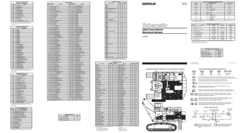
Machine Harness Connector And Component Locations
Electrical Schematic Symbols And Definitions T
39
32
4
7
3
5
26
6
Pressure Symbol
28
Circuit Breaker Symbol
Flow Symbol
Level Symbol
Temperature Symbol
24 22
1
Normally open switch that will close with an increase of a specific condition (temp-press-etc.). The circle indicates that the component has screw terminals and a wire can be disconnected from it.
29 23
17
14
42
31
13
36
40
Normally closed switch that will open with an increase of a specific condition. No circle indicates that the wire cannot be disconnected from the component.
46
This indicates that the component has a wire connected to it that is connected to ground.
25 2 18
30
20
38
37
This indicates that the component does not have a wire connected to ground. It is grounded by being fastened to the machine.
21
45
Reed Switch - A switch whose contacts are controlled by a magnet. A magnet closes the contacts of a normally open reed switch; it opens the contacts of a normally closed reed switch.
8 16 34
10 E F
9
12
D
B
15
Sender- A component that is used with a temperature or pressure gauge. The sender measures the temperature or pressure. Its resistance changes to give an indication to the gauge of the temperature or pressure.
43
11
27 A
C
44
T
41
G
19
Relay (Magnetic Switch) - A relay is an electrical component that is activated by electricity. It has a coil that makes an electromagnet when current flows through it. The electromagnet can open or close the switch part of the relay.
35 33
Solenoid - A solenoid is an electrical component that is activated by electricity. It has a coil that makes an electromagnet when current flows through it. The electromagnet can open or close a valve or move a piece of metal that can do work.
11 C D
Harness And Wire Symbols Component Part Number
E
F
G 44
43
Pin 32 23 24
22 17 B
3
39
5
28
20
15
16
Single Wire Connector
46 25
8
21 1
10
A
7
38 41 42
4 31
13
12 19
6 40
26 9
Fuse
AA
105-9344
1
325-PK-14
35
37
Wire Color
30
45 18
Socket
Wire, Cable, or Harness Assembly Identification
36
14 34
29
A
37
Sensor - Right Turbo Inlet Pressure
14
¹The FMI is a diagnostic code that indicates what type of failure has occurred.
Form Number
Vital Information Management System
GN
5
Fuel Filter Pressure
SENR6126
Solenoid - A/C Compressor
Dash Lamp Hi
Normally Closed
Starting and Charging Systems
Component
GY
338.0 ± 27.0 kPa (49.0 ± 3.9 psi)
138.0 ± 14 kPa 83 kPa MIN Normally (20.0 ± 2.0 psi) (12.0 psi MIN) Closed 362.0 ± 29.0 mN 303.0 mN MIN Normally 171-8712 Coolant Flow (1.3 ± 0.1 oz) (1.1 Oz MIN) Open at point X at point X ¹ A hysteresis band exists: with increasing pressure the closed condition can be maintained up to 2800 kpa (406 psi), with decreasing pressure the closed condition can be maintained down to 170 kpa (25 psi). 144-5661
Component Location
601
400.0 kPa (58.0 psi)
A³
513
Voltage below normal or shorted low.
Case Drain Filter Pressure Return Filter Pressure Boom Raise Pressure Swing Brake Pressure Implement Pressure
H-2
512
4
Travel Pressure
CONN 56
5 Volt Sensor Power Supply
Voltage above normal or shorted high.
115-7102
SENR6410
0262
3
A/C High/Low Pressure
Normally Closed Normally Closed Normally Open ² Normally Open Normally Closed
Machine Electronic Control System
Sensor - Turbo Outlet Pressure
Failure Description
114-5333
Contact Position
13.0 °C (55.4 °F) 860.0 ± 170.0 kPa (124.7 ± 24.7 psi) 448 ± 34 kPa (65 ± 4.9 psi) 83 kPa MIN (12.0 psi MIN)
C
CAT Data Link
FMI No.
Boom Lower Pressure
Deactuate
D-2
Machine Location
Failure Mode Identifiers (FMI)¹
3E-7808
Actuate 21.0 ± 3.0°C (69.8 ± 5.4°F) 1100.0 kPa (159.5 psi) 275 to 1750 kPa¹ (40 to 255 psi) 517 ± 34 kPa (75 ± 4.9 psi) 138.0 ± 14 kPa (20.0 ± 2.0 psi)
CONN 55
Schematic Location
diagnosed the fault.
Start Aid Temperature
SENR8737
OR
PU
Function
3E-7298
CONN 57 H-2 A³ CONN 58 Harness Code Plug E-1 A³ CONN 59 E-1 45 The connectors shown in this chart are for harness to harness connectors. Connectors that join a harness to a component are generally located at or near the component. See the Component Location Chart.
Ground - Swing Frame to RH Frame
3.00; 7.85 MAX
Engine Electronic Troubleshooting
882
M915
Solenoid:
5
876
Ladder Lamp
127-0272
34.3 ± 1.7
B-3
High Pressure Implement Filter - Rear
Flood Lamp 3-Way Sw Jumper
Solenoid:
12.0
SENR7508
Hydraulic Oil Filter
BU
104-7015
Power Shift Bucket Close Valve Bucket Open Valve Dual Pressure Relief Swing Brake Travel Brake Engine Fan Control Hydraulic Fan
Automatic Lubrication System
PK
OR
20.0 ± 0.2
Solenoid:
E
BR
641
Start Aid
100-4338
E
E455
623
Start Aid
Resistor:
Title
Ambient Air Temperature Sensor
Message Center #1
Solenoid:
9X-9584
Alternator: 9X-7803
0248
0815
9X-7137
Related Electrical Service Manuals
G423
Lighting Circuits
A/C
² Contact Position at the contacts of the harness connector.
0171
Gauge (Quad) Cluster #1
Resistor:
116-9933
7LL99-UP
Fuel Level Sensor
VIMS Interface Module #2
9X-4383
117-7881
0096
0811
33.6 Overall 3.0 ± 0.15 Tap 1.0 ± 0.05 3.3 ± 1.0
Part No.
8 Volt Sensor Power Supply
0802
10.0 ± 0.5 55.17 ± 5.77
Off Machine Switch Specification
0041
0801
42.0 ± 4.0
¹ At room temperature unless otherwise noted.
Breaker - Converter Output
Accessory Circuits
Resistance (Ohms)¹
3E-9257
0248
¹ The CID is a diagnostic code that indicates which component is faulty.
2
Part No.
33
Circuit Number Identification
Ground Connection
27
Receptacle
Wire Gauge Plug 2
200-BK-14
Pin or Socket Number
2
1 2
Typical representation of a Deutsch connector. The plug contains all sockets and the receptacle contains all pins.
1 2
Typical representation of a Sure-Seal connector. The plug and receptacle contain both pins and sockets.