Schematic Location
Component
5
C
14
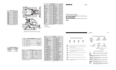
Connector Location Connector Number CONN 1 CONN 2 CONN 3 CONN 4 CONN 5 CONN 6 CONN 7 Diagnostic CONN 8 CONN 9 CONN 10 CONN 11 CONN 12 CONN 13 CONN 14 CONN 15 CONN 16 CONN 17 CONN 18 CONN 19 CONN 22 CONN 23 CONN 24 CONN 25 CONN 26 CONN 27 CONN 28 CONN 29 CONN 30
E
2
Schematic Location F-9 E-9 E-9 D-9 A-8 E-8 F-8 F-7 C-7 A-7 D-6 F-5 D-5 C-S C-5 C-4 F-4 C-3 B-3 D-2 D-2 D-2 D-2 E-2 E-2 F-2 F-2 F-1
Machine Location C C C C C C C C 1 15 A C A A A A C B A 18 18 18 18 18 18 18 18 7
10 18
11
4
B
15 8 22
11
4
The connectors shown in this chart are for harness to harness connectors. Connectors that join a harness to a component are generally located at or near the component. See the Component Location Chart.
7
21 6
19
3
1
9
B
D
C
20
14 5
16
12
20 17
2
9
A
D
13
1
17
A
E
8 10 12
16
21 18
15
22
13 19 6
Alarm - Action
E-5
Alarm - Backup
F-9
Alternator
Component Location Machine Location
Component
Schematic Location
Machine Location
1
Relay - Grapple 2
C-8
2
Relay - Main
F-7
C
B-2
3
Relay - Start
F-7
C
Assembly - Grapple Control Handle
B-6
D
Resistor - Blower Motor
A-3
8
Assembly - Relay
D-9
4
Resistor - Starter/Diagnostic
C-2
6
Batteries
F-9
5
Sender - Coolant Temp
E-2
13
Breaker - Alternator
F-8
C
Sender - Fuel Level
E-9
14
Breaker - Blower Motor
F-6
C
Sender - Powertrain Oil Temp
E-2
15
Electronic Monitoring System
E-6
A
Solenoid - Air Conditioner
F-1
16
Fuse - Front Dash and Dome Lamp
F-B
C
Solenoid - Grapple Rotate
A-9
17
Fuse - Key
F-B
C
Solenoid - Grapple Swing
B-9
17
Fuses
F-7
C
Solenoid - Grapple Tong
B-9
17
Gauge - Coolant Temp
C-4
A
Solenoid - Start Aid
F-2
16
Gauge - Fuel Level
C-4
A
Switch - A/C Refrigerant Press
F-2
16
Gauge - Powertrain Oil Temp
C-4
A
Switch - Auto Grab
B-4
D
Ground - Engine Block
B-2
6
Switch - Backup Alarm
E-7
E
Ground - Frame
B-2
6
Switch - Blower
B-3
A
Ground - Frame
F-9
C
Switch - Disconnect
F-9
C
Ground - Module
E-5
A
Switch - Engine Coolant Temp
F-1
13
Ground - Module
F-8
C
Switch - Engine Oil Press
D-1
18
Ground - Module
F-9
C
Switch - Forward Horn
D-6
D
Horn - Forward
F-1
7
Switch - Front Dash and Dome Lamp
C-6
A
Lamp - Master Action
D-6
A
Switch - Front Wiper
B-7
B
Lighter-Cigar
D-6
A
Switch-Fuel Press
C-1
19
Meter - Service
D-6
A
Switch - Grapple Press
C-9
17
Motor - Blower
B-3
8
Switch - Hydraulic Oil Temp
E-9
20
Motor - Blower
D-9
4
Switch - Key Start
C-6
A
Motor - Front Washer
F-8
C
Switch - Left Wiper
B-7
B
Motor - Front Wiper
E-4
9
Switch - Neutral Start
E-7
E
Motor - Left Washer
F-8
C
Switch - Operator Monitor Test
D-6
A
Motor - Left Wiper
E-7
10
Switch - Powertrain Filter Press
A-7
15
RENR2032 August 1998
1
Motor - Rear Washer
F-9
C
Switch - Powertrain Oil Temp
E-1
15
Motor - Rear Wiper
D-8
11
Switch - Powertrain Temp
A-7
15
Motor - Right Washer
F-9
C
Switch - Rear and Side Lamp
C-6
A
Motor - Right Wiper
B-6
12
Switch - Rear Wiper
B-8
B
Motor - Starter
C-2
6
Switch - Right Wiper
B-8
B
Power Post
F-7
C
Switch - Start Aid
D-6
A
Radio Relay - Grapple 1
C-3 C-8
B 1
Switch - Start Aid Coolant Temp Thermostat
F-2 B-3
21 A
517 Track Skidder Electrical System 6PW1-UP 5WW1-UP
Machine locations are repeated for components located close together.
7
A = Located on dash. B = Located in cab overhead.
3
C = Located in fuse panel. D = Located in operator’s right side console. E = Located in operator’s left side console.
D90909
Machine Harness Connector And Component Locations Printed in U.S.A.
© 1998 Caterpillar All Rights Reserved
Wire Number
Wire Color
101
RD
Wire Number
Wire Color
Bat(+)
500
BR
Wiper - Front (Park)
102 105
RD
Hd Lmp
501
GN
Wiper - Front (Low)
RD
Key Sw
502
OR
Wiper - Front (HI)
109
RD
Alt Output (+) Term.
503
BR
Wiper - Rear (Park)
112
PU
Main Power Rly Output
504
YL
Wiper - Rear (Low)
113
OR
Opr Mon Panel B (+) Switched
505
BU
Wiper - Rear (HI)
114
RD
Warning Horn (Forward)
506
PU
Washer - Front
116
BR
Aux Ckt
507
WH
Washer - Rear
118
GY
Aux Ckt
508
PU
Radio Speaker - Left
Description Power Circuits
Resistor, Sender and Solenoid Specifications
Part No.
Component Description
3E-1906
Resistance (Ohms)¹
Solenoid - A/C Clutch
2G-0413
Resistor - OROPS Heater
9G-1950
Resistor - Blower Speed
9G-4365
Solenoid - Start Aid
6N-5926
17.6±0.6 5 Overall 2.0 ± 0.1 Tap 1.0 ± 05
6
Sender - Coolant Temperature
8N-3844
Sender - Powertrain Oil Temp
6T-2217
Resistor - Starter/Diagnostic
123-7408
Sender - Fuel Level
PK
Aux Ckt
509
WH
Radio Speaker - Left (Commom)
524-586 @ 115.6°C(240.1°F) 5806-586 @ 54.4°C(129.9°F)
121
RD
Back Alarm To Lamp
511
BR
Radio Speaker - Right
123
WH
Aux Ckt
512
GN
Radio Speaker - Right (Common)
124
GN
A/C
513
OR
A/C Compressor/Refrigerant Pressure SW
129
BU
Aux Ckt
515
GY
Blower Motor (HI)
158
BR
Aux Ckt Ground Circuits
516
GN
Blower Motor (Medium)
517
BU
Blower Motor (Low)
200
BK
Main Chassis
521
YL
A/C SW To Refrigerant SW
201
BK
Operator Monitor Return
522
WH
A/C Clutch To Thermostat SW
203
BK
Chassis Diagnostic
523
BR
Wiper - Left (Park)
207
BK
Starter Diagnostic Basic Machine Circuits
524
BU
Wiper - Left (Low)
525
GY
Wiper - Left (HI)
150 ± 75 Full: 27.5 - 39.5 Empty: 240-260
Form Number SENR7508
Electronic Monitoring System
SENR2945
Starting and Charging
SENR2947
Starting Motor: 106-8555 Consist No. 6V-5207 Consist No. 6V-5023 Consist No.6V-5226
SENR3581 SENR3536 SENR4979
Part No.
Function
Off Machine Switch Specification
3E-2026 Engine Oil Pressure 3E-2028 Engine Coolant Temperature 3E-6425 Coolant Temp (St Aid) 3E-6451 Hydraulic Oil Temperature 3E-6453 Powertrain Oil Temperature 3E-9350 Powertrain Filter Bypass Temperature 9X-7781 Power Train Filter Pressure 107-0616 Fuel Pressure 114-5334 Refrigerant Pressure (AC) 135-7748 Grapple Pressure
Actuate 60 kPa MAX (8.7 psi MAX) 107.0 ± 3.0°C (224.6 ± 5.4 °F) 38.0 ± 3.0°C (100.0 ± 5.0°F) 107.0 ± 3.0°C (224.6 ± 6.0°F) 129.0 ± 3.0°C (264.0 ± 6.0°F) 52 ± 3°C (125.6 ± 5.4°F) 210 ± 70 kPa (30 ± 10 psi) 93 ± 21 kPa (13.5 ± 3.0 psi) 275 to 1750 kPa¹ (40 to 255 psi) 20103 ± 517 kPa (2915.7 ± 74.9 psi)
Accessory Circuits
119
Related Electrical Service Manuals Alternator: 114-2401
Description
524-586 @ 115.6°C(240.1°F) 5806-586 @ 54.4°C(129.9°F)
¹ At room temperature unless otherwise noted.
Title
Harness And Wire Electrical Schematic Symbols
Wire Description
Deactuate 38 ± 20 kPa (5.5 ± 2.9 psi) 93.00°C (199.4 °F) 27.0°C MIN (81 .0°F MIN) 93.0°C MIN (199.0°F MIN) 118.0°C MIN (244.0°F MIN) 43°C MIN (109.4°F MIN) — — 69 ± 21 kPa (10.0 ± 3.0 psi) — — 18517 ± 517 kPa (2685.6 ± 74.9 psi)
301
BU
Starter No. 1 Sol
526
YL
Wiper - Right (Park)
302
OR
Starter No. 1 Resistor To Diagnostic
527
GN
Wiper - Right (Low)
304
WH
Starter Relay No. 1 Output
528
PK
Wiper - Right (HI)
306
GN
Starter Relay Coil To Neut Start SW Or Key SW
529
WH
Washer Left
308
YL
Main Power Relay Coil
530
OR
Washer Right
310
PU
Start Aid SW To Start Aid Sol
592
BU
DC/DC Converter Power Output
311
WH
Start Aid Sol To Temp SW
593
GN
321
BR
Bckp Alarm
Condenser Fan Relay To Motors Lighting Circuits
322
GY
Warning Horn (Forward) Monitoring Circuits
600
BR
Dash Lamp Basic
607
PK
Flood Lamp - Front
GN
Alternator (R) Term.
608
GN
Flood Lamp - Rear
404
YL
Opr Mon Hyd Oil Temp
609
YL
Flood Lamp - Side
405
GY
Opr Mon Oil Press. (Low Setting)
610
OR
Head Lamp Basic
406
PU
Opr Mon Coolant Temp
630
GY
Flood Lamp Rear (Attach)
Normally Open
410
WH
Opr Mon Action Alarm
A513
PK
DC/DC Converter Memory Output
411
PK
Opr Mon Master
E852
YL
Grapple Tong Close Press Sensor
Normally Closed
413
BR
Opr Mon Fuel Press.
E853
PU
Grapple Tong Open Sol
415
GN
Opr Mon Test SW
E854
GN
Grapple Tong Close Sol
424
GY
Opr Mon Power Train Temp
E855
WH
Grapple Rotate CW Sol
426
BR
Opr Mon Power Train Oil Filter
E856
GY
Grapple Rotate CCW Sol
441
OR
Eng Coolant Temp Gauge
F838
BR
Grapple Tong Close Auto/Manual SW
443
YL
Power Train Temp Gauge
F839
OR
Grapple Tong Off Input
447
PK
Fuel Level Gauge
K932
GN
Swing Sol Left
K934
GN
Swing Sol Right
Contact Position Normally Open Normally Closed Normally Closed Normally Closed Normally Closed Normally Closed
Normally Open² Normally Closed
¹ A hysteresis band exists: with increasing pressure the closed condition can be maintained up to 2800 kPa (405 pressure the closed condition can be maintained down to 170 kPa (25 psi). ² Contact position at the contacts of the harness connector.
403
A
Electrical Schematic Symbols And Definitions
AA
Typical representation of a Deutsch connector. The plug contains all sockets and the receptacle contains all pins.
Receptacle
Plug
1 2
1 2
1
2
Typical representation of a Sure-Seal connector. The plug and receptacle contain both pins and sockets.
T
Pressure Symbol
Temperature Symbol
Level Symbol
Flow Symbol
Pin or Socket Number Wire, Cable, or Harness Assembly Identification
Component Part Number
Single Wire Connector C
Normally open switch that will close with an increase of a specific condition (temp-press-etc.).
A
A 325-PK-14
Pin
Normally open switch that is closed due to an applied condition, and will open again with a specific decrease in that condition.
AA 1
Wire Color
Socket
2
Normally closed switch that will open with an increase of a specific condition.
Wire Gauge
Electrical Schematic Symbols And Definitions FUSE - A component in an electrical circuit that will open the circuit if too much current flows through it.
The circle indicates that the component has screw terminals and a wire can be disconnected from it.
REED SWITCH - A switch whose contacts are controlled by a magnet. A magnet closes the contacts of a normally open reed switch; it opens the contacts of a normally closed reed switch.
No circle indicates that the wire cannot be disconnected from the component. T
This indicates that the component does not have a wire connected to ground. It is grounded by being fastened to the machine.
200-BK-14
Circuit Number Identification
Normally closed switch that is open due to an applied condition, and will close again with a specific decrease in that condition.
This indicates that the component has a wire connected to it that is connected to ground.
9X-1123 325-PK-14
SENDER - A component that is used with a temperature or pressure gauge. The sender measures the temperature or pressure. Its resistance changes to give an indication to the gauge of the temperature or pressure. RELAY (Magnetic Switch) - A relay is an electrical component that is activated by electricity. It has a coil that makes an electromagnet when current flows through it. The electromagnet can open or close the switch part of the relay. CIRCUIT BREAKER (C/B) - A component in an electrical circuit that will open the circuit if too much current flows through it. This does not destroy the circuit breaker and it can be reset to become part of the circuit again. SOLENOID - A solenoid is an electrical component that is activated by electricity. It has a coil that makes an electromagnet when current flows through it. The electromagnet can open or close a valve or move a piece of metal that can do work. MAGNETIC LATCH SOLENOID - A magnetic latch solenoid is an electrical component that is activated by electricity and held latch by a permanent magnet. It has two coils (latch and unlatch) that make electromagnet when current flows through them. It also has an internal switch that places the latch coil circuit open at the time the coil latches.