Component Location Alarm-Action
Schematic Location D-5
Machine Location B
Schematic Location E-1
Machine Location 20
Alarm-Backup
A-9
1
Alternator
C-2
21
Solenoid-Cable Winch In
B-9
3
Solenoid-Cable Winch Out
C-9
Batteries-12V
F-2
3
23
Solenoid-Differential Lock
C-9
Breaker-Lamps Circuit (15A)
3
A-2
C
Solenoid-Fuel Shutdown
C-2
C
Breaker-Main (80A)
A-3
C
Solenoid-Grapple Rotate
A-9
1
Control-Caterpillar Monitoring System
E-4
B
Solenoid-Grapple Tong
A-9
1
Control-Relay
C-3
C
Solenoid-Start Aid
E-2
18
Control-Secondary Steering
E-3
C
Solenoid-Transmission Valves
E-9,F-9
13
Control-Steering Wheel Group
B-5
B
Solenoid-Winch Free Spool
Control-Transmission/Grapple
A-5
B
Suppressor-Arc
Converter-24 to 12 Volts
E-4
15
Fuses-10A,15A,20A
B2
Gauge-Quad Ground-Cab Roof
Component
8
10 12
17
4
2
5
3
1
18
15 7
11
20
D
B
22
23
9 13
6
A
14
21
19
C 16
7
10
14
15
17
B A
4
C
8 9
3 1
18 12
21 19
D
22
20
13
23
2 5
11
C-9
3
B-9,C-9
20
Suppressor-Arc A/C
F-2
3
C
Switch-Accumulator Charge Pressure
C-3
C
E-4
B
Switch- Blower
B-8
A
A-7
A
Switch-Cat Monitor Sys. Select
C-5
B 20
C-2
21
Switch-Coolant Temp
D-1
21
Switch-Differential Lock
B-8
A
Ground-Lower Cab to Frame
A-7
9
Switch-Disconnect
F-2
21
Ground-Platform
C-7
9
Switch-Engine Oil Pressure
D-2
19
Handle-Grapple Control Assembly
A-8
A
Switch-Forward Horn
B-5
B
Horn-Forward
D1
11
Switch-Front Differential Pressure
F-5
12
Lamp-Action
D-5
B
Switch-Front Lamp
D-6
14
Lamp-Primary Steering Press. Warning
C-6
B
Switch-Front Wiper
E-6
14
Lamp-Secondary Steering Press. Warning
C-6
B
Switch-Front/Rear Washer
E-6
14
Motor-Blower
D-7
7
Switch-Grapple Auto/Manual
C-7
B
Motors-Front and Rear Washer
F-7
8
Switch-Key Start
C-6
B
Motor-Front Wiper
F-3
17
Switch-Left Defrost Fan
F-5
14
Motor-Left and Right Defrost Fan
F-5
7
Switch-Park Brake Pressure
D-3
C
Motor- Rear Wiper
A-8
6
Switch-Primary Steering Pressure
F-3
3
Motor-Secondary Steer
D-2
3
Switch-Rear Wiper
E-6
14
Motor-Starter
C-2
19
Switch-Rear/Center Lamp
D-6
14
Receptacle-Aux. Start
F-2
21
Switch-Refrigerant
E-2
20
Relay-Grapple Solenoid Return
A-4
B
Switch-Right Defrost Fan
F-6
14
Relay-Main
A-2
C
Switch-Secondary Steering Pressure
E-3
3
Relay-Secondary Steer
D-2
3
Switch-Secondary Steering Test
C-5
B
Relay-Spool Control
B-6
A
Switch-Spool Control
B-7
A
Relay-Start
A-3
C
Switch-Spool Direction
B-7
A
Resistor-Blower
C-8
A
Switch-Start Aid
C-6
B
Sender-Converter Temp
E-9
13
Switch-Transmission Filter Pressure
F-8
13
Sender-Coolant Temp
D-3
20
Switch-Transmission Neutral Lock
C-6
B
Sender-Fuel Level
B-9
2
Switch-Winch Position
C-9
3
Sender-Hydraulic Temp
D-3
18
Thermostat
D-8
7
Sensor-Grapple Pressure Group
A-9
B
Ground-Frame
6
Solenoid-A/C Clutch
A-7,C-2,F-2
Ground-Engine Block
16
Component
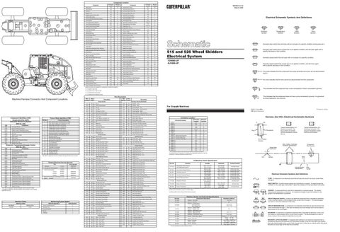
Electrical Schematic Symbols And Definitions
T
Temperature Symbol
Pressure Symbol
Flow Symbol
Level Symbol
Normally open switch that will close with an increase of a specific condition (temp-press-etc.).
Normally open switch that is closed due to an applied condition, and will open again with a specific decrease in that condition.
Normally closed switch that will open with an increase of a specific condition.
1DN980-UP 4LR306-UP
Normally closed switch that is open due to an applied condition, and will close again with a specific decrease in that condition.
The circle indicates that the component has screw terminals and a wire can be disconnected from it.
No circle indicates that the wire cannot be disconnected from the component.
Machine locations are repeated for components located close together.
This indicates that the component has a wire connected to it that is connected to ground.
A = Located in dash area. B = Located inside of right console. C = Located around relay panel. D = Located around hydraulic oil tank.
This indicates that the component does not have a wire connected to ground. It is grounded by being fastened to the machine.
Wire Description
Machine Harness Connector And Component Locations
Wire Number
Wire Color
Wire Number
Wire Color
101
RD
Bat (+)
506
PU
103
Washer - Front
YL
Panel Lamps/Gauges
507
WH
Washer - Rear
105
RD
Key Sw
508
PU
Radio Speaker - Left
108
BU
Op. Seat
509
WH
Radio Speaker - Left (Common)
109
RD
Alt Output (+) Term.
511
BR
Radio Speaker - Right
112
PU
Main Power Relay Output
512
GN
Radio Speaker - Right (Common)
114
RD
Warning Horn (Forward)
513
OR
A/C Compressor/Refrigerant Pressure SW
115
RD
STD Lamps
515
GY
Blower Motor (HI)
118
GY
Front Washer and Wiper Ckt
516
GN
Blower Motor (Medium)
BU
Blower Motor (Low)
Description Power Circuits
Component Identifiers (CID¹) Module Identifier (MID²) Caterpillar Monitoring System (MID No. 030)
Failure Mode Identifiers (FMI)¹ FMI No.
Failure Description
A
F-7
10
CONN. 8
B-5
B
CONN. 9 - Service Tool Connector
D-5
B B
Front Defroster Fan (Lo)
PK
Defrost Fans
A504
GN
GY
Spool Control
A506
OR
0248
Data Link
Parking Brake Switch
A-7
CONN. 7
DC/DC Converter Power Output
PK
146
0070
CONN. 6
BU
A503
Current above normal or grounded circuit.
Component
Front Defroster Fan (Hi)
592
Secondary Steering
Current below normal or open circuit.
CID
A
Attach Lamps
GN
6
Electronic Transmission/Grapple Control (MID No. 081)
C-8,F-2
OR
136
5
Display Power Supply
CONN. 5
127
Torque Converter Oil Temperature Sensor
Display Data Link
4
Rear Defroster Fan (Lo)
A/C Clutch To Thermostat SW
Engine Coolant Temperature Sensor
0821
5
D-8
WH
0177
0819
F-9
CONN. 4
A/C SW To Refrigerant SW
522
0110
Hydraulic Oil Temperature Sensor
CONN. 3
YL
XMSN Ctrl
141
0600
1
521
PK
4
Action Lamp
D-9
A/C
126
Engine Oil Pressure Sensor
Action Alarm
CONN. 2
GN
Data valid but below normal operational range.
0100
0324
1
124
1
Voltage above normal or shorted high.
0271
B-9
517
Data erratic, intermittent, or incorrect.
Sensor Power Supply
CONN. 1
Rear Washer and Wiper Ckt
3
0263
Machine Location
PK
2
Voltage below normal or shorted low.
7
Mechanical system not responding properly.
8
Abnormal frequency, pulse width, or period.
9
Abnormal update.
10
Abnormal rate of change.
165
YL
Differential Lock Ground Circuits
A507
YL
Rear Defroster Fan (Hi)
A513
PK
DC/DC Converter Memory Output Lighting Circuits
BK
Main Chassis
CONN. 10 - Service Mode Plug
D-5
201
BK
Operator Monitor Return
607
PK
Flood Lamp - Front
CONN. 11 - Harness Code Plug
E-5
B
202
BK
XMSN Ctrl
608
GN
Flood Lamp - Rear
CONN. 12
C-4
C
11
Failure mode not identifiable.
12
Bad device or component.
13
Out of calibration.
270
BK
CAT Mon Sys Ident Code 0
614
PU
Park/Tail/Dash Lamp
CONN. 13
B-4
C
14
Parameter failures.
271
BK
CAT Mon Sys Ident Code 1
630
GY
Flood Lamp Rear (Attach)
CONN. 14
B-3
C
15
Parameter failures.
272
BK
CAT Mon Sys Ident Code 2
CONN. 15
D-3
C
16
Parameter not available.
273
BK
CAT Mon Sys Ident Code 3
727
GN
Secondary Steering Relay
CONN. 16
C-2
C
274
BK
CAT Mon Sys Ident Code 4
751
GN
XMSN Shift Sol No. 1 or 3
CONN. 17
B-2
C
CONN. 18
A-2
C
275
BK
CAT Mon Sys Ident Code 5
752
YL
XMSN Shift Sol No. 2
290
BK
CAT Mon Sys Service
754
BU
XMSN Shift Sol No. 3 or 1
291
BK
CAT Mon Sys Clear
755
OR
XMSN Shift Sol No. 4 or 5
E707
GN
Display +V
17
Module not responding.
18
Sensor supply fault.
Control Circuits
Electrical System Voltage
0248
CAT Data Link
0368
Transmission Auto/Manual Switch
0417
Grapple Solenoid Return Voltage
0444
Start Relay
301
BU
Starter No. 1 Sol
E708
PK
Display Clock
0449
Grapple Rotate Switch
304
WH
Starter Relay No. 1 Output
E735
PU
Cat Mon Sys Tach/Serv Mtr/Odometer Select Sw
0450
Tong Position Switch
306
GN
Starter Relay Coil
G750
BU
XMSN Control Forward Sw
0451
Grapple Clockwise Solenoid
OR
Key Start Sw To Neutral Start Sw
G755
GY
XMSN Control Reverse Sw
Grapple Counterclockwise Solenoid
Form Number
307
0452 0453
Tong Open Solenoid
Alternator:
114-2401
SENR7508
308
YL
Main Power Relay Coil
G760
WH
XMSN Control Speed 2 Sw
0454
Tong Close Solenoid
Caterpillar Monitoring System:
175-0027
SENR1394
310
PU
Start Aid SW To Start Aid Sol
G761
YL
XMSN Control Speed 3 Sw
0455
Tong Closed Pressure Sensor
Electric Starting Motor:
0621
Downshift Switch
0622
Upshift Switch
0623
Directional Switch
Consist:
0631
Transmission Clutch 1 Solenoid (Forward High)
0632
Transmission Clutch 2 Solenoid (Reverse)
0633
Transmission Clutch 3 Solenoid (Forward Low)
0634
Transmission Clutch 4 Solenoid (Speed)
19 20
Condition not met. Parameter failures.
¹The FMI is a diagnostic code that indicates what type of failure has occurred.
Related Electrical Service Manuals Title
Basic Machine Circuits
106-8555
311
WH
Start Aid Sol To Temp SW
G762
BR
XMSN Control Speed 4 Sw
Consist:
6V-5023
SENR3536
321
BR
Backup Alarm
G763
PU
XMSN Control Neutral SW
Consist:
6V-5207
SENR3581
322
GY
Warning Horn (Forward)
G768
GN
XMSN Control Speed 1 SW
6V5226
SENR4975
322
GY/BK
Forward Horn Sw
E851
BU
Grapple Rotate CCW Select Sw
324
BU
Diff Lock Sol
E852
YL
Grapple Tong Closed Pressure Sensor
326
PU
Key SW "C" Term.
E853
PU
Grapple Tong Open Sol
E854
GN
Grapple Tong Closed Sol
Electronic Transmission and Grapple Control System : 169-5426
SENR6686
Monitoring Circuits 403
GN
Alternator (R) Term.
E855
WH
Grapple Rotate CW Sol
GY
Grapple Rotate CCW Sol
0635
Transmission Clutch 5 Solenoid (Speed)
0636
Transmission Clutch 6 Solenoid (Speed)
405
GY
Opr Mon Oil Press. (Low Setting)
E856
0687
Options ID Code
410
WH
Opr Mon Action Alarm
F838
BR
Grapple Tong Close Auto/Manual Sw
411
PK
Opr Mon Master
F839
OR
Grapple Tong Off Input
¹ The CID is a diagnostic code that indicates which component is faulty. ² The MID is a diagnostic code that indicates which electronic control module diagnosed the fault.
Machine Codes
Monitoring System Modes
Machine Codes
Mode Of Operation Machine Code
515,525
51,60
Connector Number
200
0168
Sale Model
Harness And Wire Electrical Schematic Symbols
Connector Location ¹ Schematic Location
119
Data valid but above normal operational range.
Fuel Level Sender
Component
Accessory Circuits (Continued)
0
0096
CID
Description
Mode Number
Operator Mode Sequence
0
Harness Code
1
Numeric Readout
2
Service
3
Tattletale
4
A
2
Wire, Cable, or Harness Assembly Identification
C
¹ The connectors shown in this chart are for harness to harness connectors. Connectors that join a harness to a component are generally located at or near the component. See the Component Location Chart.
Pin
Part No. 117-7773
Function Transmission Filter Pressure Front Differential Pressure
3E-7806
Accumulator Charge Pressure
3E-7807
Park Brake Pressure
3E-7808
Secondary Steering Pressure
128-5091
Primary Steering Pressure
114-5333
Refrigerant Pressure
Actuate
Deactuate
Contact Position
138.0 ± 28.0 kPa (20.0 ± 4.0 psi)
69.0 kPa MIN (10.0 psi MIN)
Normally Closed
9500 kPa MAX (1375 psi MAX) 4000 kPa MAX (580 psi MAX) 1100 kPa MAX (160 psi MAX) 551.0 kPa MAX (80.0 psi MAX)
8300 ± 350 kPa (1200 ± 50 psi) 3500 ± 110 kPa (510 ± 16 psi) 860 ± 110 kPa (125 ± 25 psi) 344.0 ± 20.0 kPa (50.0 ± 3.0 psi)
A-B,Normally Open A-C,Normally Closed A-B,Normally Open A-C,Normally Closed A-B,Normally Open A-C,Normally Closed A-B,Normally Open A-C,Normally Closed
275 to 1750 kPa¹ (40 to 255 psi)
_ _
Primary Steering Pressure Sw
F840
YL
Grapple Rotate Off Input
F868
OR
Winch Sol Cable Out
² Contact position at the contacts of the harness connector.
426
BR
Opr Mon Power Train Oil Filter
F869
PK
Winch Sol Cable In
432
PK
Opr Mon Brake Pressure (Oil)
F870
BU
Winch Freespool Sol
441
OR
Eng Coolant Temp Gauge
F877
WH
Spool Control Sw to Spool Control Relay
442
GY
Hyd System Temp Gauge
F878
BR
Spool Control Relay to Spool Direction SW
101-5459
Engine Oil Pressure
YL
Power Train Temp Gauge
F879
PK
Winch Position Sw
447
PK
Fuel Level Gauge
900
PU
XMSN Shift Sol No. 5 or 4
3E-6332
453
PK
Secondary Steering Pressure Sw
901
WH
XMSN Shift Sol No. 6
484
YL
Primary Steering Pressure Indicator
921
WH
XMSN Sol No. 1 or 3 Return
498
WH
Diff. Lock Indicator
944
OR
Data Link + (Cat)
C413
YL
Display Data
945
BR
Data Link - (Cat)
C414
BU
Display Load
961
BR
Grapple Rotate CW Select Sw
C436
BU
Differential Filter Pressure Sw
991
WH
XMSN Neutral Lock
Accessory Circuits
C903
BU
Grapple Sol Return Relay
Wiper - Front (Low)
C907
WH
Tong Closed Select Sw
502
OR
Wiper - Front (HI)
K927
BU
Grapple and Tong Solenoids Return
503
BR
Wiper - Rear (Park)
K932
GN
Grapple Swing CW Sol
504
YL
Wiper - Rear (Low)
K934
GN
Grapple Swing CCW Sol
505
BU
Wiper - Rear (HI)
Wire Gauge
Electrical Schematic Symbols And Definitions FUSE - A component in an electrical circuit that will open the circuit if too much current flows through it. REED SWITCH - A switch whose contacts are controlled by a magnet. A magnet closes the contacts of a normally open reed switch; it opens the contacts of a normally closed reed switch.
Normally Open Normally Closed
SENDER - A component that is used with a temperature or pressure gauge. The sender measures the temperature or pressure. Its resistance changes to give an indication to the gauge of the temperature or pressure.
Resistor, Sender and Solenoid Specifications Part No.
443
GN
200-BK-14
Circuit Number Identification
T
3E-1906
501
9X-1123 325-PK-14
Wire Color
Socket
2
Normally Open²
Opr Mon Parking Brake
Tong Open Select Sw
AA 1
Off Machine Switch Specification
YL
PU
A
A 325-PK-14
GY
C906
Component Part Number
Single Wire Connector
417
Wiper - Front (Park)
Typical representation of a Sure-Seal connector. The plug and receptacle contain both pins and sockets.
Pin or Socket Number
419
BR
Typical representation of a Deutsch connector. The plug contains all sockets and the receptacle contains all pins.
Receptacle
Plug
1 2
1 2
1
90.0 kPa MAX 70.0 ± 20.0 kPa (13.0 psi MAX) (10.0 ± 3.0 psi) 38.0 ± 3.0°C 27.0°C MIN 3E-6425 Coolant Temperature (100.4 ± 5.4°F) (80.6°F MIN) ¹ With increasing pressure the closed condition can be maintained up to 2800 kPa (405 psi), with decreasing pressure the closed condition can be maintained down to 170 kPa (25psi).
500
AA
Component Description Solenoid - A/C Clutch
186-1526
Solenoid - Start Aid Solenoid - Fuel Shutdown Start (Latch) Coil Stop (Unlatch) Coil Solenoid - Grapple Rotate Solenoid - Grapple Tong Solenoid - Cable Winch In/Out Solenoid - Winch Freespool Solenoid - Differential Lock Solenoids - Transmission Valves
9G-1950
Resistor - Blower Motor Speed
157-8852
Sender - Fuel Level
7N-8532
Sender - Converter Sender - Coolant
4W-9972
Sender - Hydraulic
155-4653
126-7971 152-8385
¹ At room temperature unless otherwise noted.
Resistance (Ohms)¹ 17.6 ± 0.6 6.0 1.55 ± 0.15 10.3 ± 1.03 12.0 32.6 ± 1.6 31.0 ± 3.0 Overall 2.0 ± .1 ; Tap 1.0 ± .05 Empty: 92 - 98 Full: 0 - 3.5 54°C (130°F) - 560 to 716 110°C (230°F) -72 to 82 54°C (130°F) - 560 to 716 110°C (230°F) - 72 to 82
RELAY (Magnetic Switch) - A relay is an electrical component that is activated by electricity. It has a coil that makes an electromagnet when current flows through it. The electromagnet can open or close the switch part of the relay. CIRCUIT BREAKER (C/B) - A component in an electrical circuit that will open the circuit if too much current flows through it. This does not destroy the circuit breaker and it can be reset to become part of the circuit again. SOLENOID - A solenoid is an electrical component that is activated by electricity. It has a coil that makes an electromagnet when current flows through it. The electromagnet can open or close a valve or move a piece of metal that can do work. MAGNETIC LATCH SOLENOID - A magnetic latch solenoid is an electrical component that is activated by electricity and held latch by a permanent magnet. It has two coils (latch and unlatch) that make electromagnet when current flows through them. It also has an internal switch that places the latch coil circuit open at the time the coil latches.