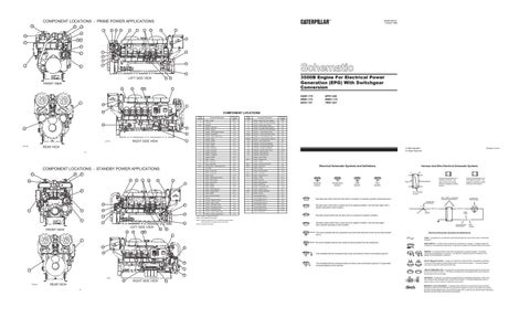
COMPONENT LOCATIONS - PRIME POWER APPLICATIONS 26
25
SENR1005-01 October 1996
21 18
19
15
16
20
7
9
14
21
25
15 23 18
21a
19
16 24
11
17
11 10 8
1
3
6
3
5
LEFT SIDE VIEW
29
3500B Engine For Electrical Power Generation (EPG) With Switchgear Conversion
30
FRONT VIEW 26
1
22
28 32
1
4GM1-170 8RM1-174 6HN1-137
23
2
COMPONENT LOCATIONS
23a
Engine Location 1
27 12
17
31
RIGHT SIDE VIEW
D31775
4
REAR VIEW
D31778
25
21
14
23
9
7
20
25
21 21A
24
11
11
1
17
10 6
Engine Location 15
Component Description Sensor - Engine Oil Press (Filtered)
Schematic Location D-3
Alternator
D-6
16
Sensor - Engine Oil Press (Unfiltered)
D-3
note 1
Batteries
D-5
17
Sensor - Engine Speed Timing
C-3
1
Breaker - Alternator
D-9
18
Sensor - Fuel Filter Press (Filtered)
D-3
1
Breaker - Battery
D-9
19
Sensor - Fuel Filter Press (Unfiltered)
D-3
1
Breaker - ECM (Engine Control)
A-10
20
Sensor - L. Turbo Exhaust Temp
C-3
1
Breaker - Mag Relay
D-9
21/21a
Sensor - L. Turbo Inlet Press (note 3)
D-3
1
Breaker - Main Crank E-Stop
D-9
22
Sensor - R. Turbo Exhaust Temp
C-2
1
Breaker - Relay
C-9
23/23a
Sensor - R. Turbo Inlet Press (note 3)
D-4
1
Breaker - SEMS
B-12
24
Sensor - Turbo Outlet Press
D-3
3
Control - Engine
A-5
25
Solenoid - Air Shut-off (Left Side)
F-1
1
Control - Speed
C-10
26
Solenoid - Air Shut-off (Right Side)
F-1
1
Gauge - Cluster #1
F-11
27
Solenoid - Air Start (if equipped)
E-5
1
Gauge - Cluster #2
F-10
28
Solenoid - Cylinder Head (note 2)
A-1/B-1
1
Gauge - Cluster #3
F-10
29
Solenoid - Ether Start Aid
1
Module - Loadshare
F-6
30
Solenoid - Ether Start Aid
E-1
1
Monitor - SEMS
E-12
1
Switch - Alarm Silence
E-11
4
Motor - Prelube
E-1
note 1
Switch - Charger Fault
F-3
5
Motor - Starter #1
D-6
1
6
Motor - Starter #2
E-6
note 1
Switch - Customer Shut-down
F-3
Potentiometer - Speed Adjustment
E-7
note 1
Switch - Disconnect
D-5
1
Pyrometer
D-2
1
Switch - E-Stop
B-10
1
Relay - Air Shut-off
C-10
1
Switch - Ether Auto/Man
A-10
1
Relay - Air Shut-off
C-10
note 1
Switch - Fuel Level
F-3
1
Relay - Dnoxr
A-9
note 1
Switch - Genset On Line
F-3
1
Relay - ECM (Engine Control)
B-11
1
Switch - LH/RH
D-11
1
Relay - Ether Hold-in
E-10
1
Switch - Low Idle
C-9
1
Relay - Ether Pull-in
E-10
1
Switch - Manual Crank
D-11
1
Relay - Mag #1
D-10
1
Switch - Mode/Clear
D-11
1
Relay - Mag #2
D-10
1
Switch - Overspeed Verify
A-10
1
Relay - Prelube (Master)
D-10
31
Switch - Prelube Press
B-4
1
Relay - Prelube (Slave)
D-10
note 1
1
Relay - SEMS
B-11
1
Switch - Service
D-11
1
Relay - Shut-down Notify
E-8
1
Terminal Block (TB-1)
D-9
7
Resistor
E-1
1
Terminal Block (TB-10)
B-8
8
Sender - Engine Oil Temp
F-1
1
Terminal Block (TB-11)
A-8
9
Sender - Inlet Air Temp
F-1
1
Terminal Block (TB-12)
E-8
10
Sensor - Aftercooler Temp
D-4
1
Terminal Block (TB-3)
A-12
11
Sensor - Atmospheric Press
D-3
1
Terminal Block (TB-4)
D-9
12
Sensor - Crankcase Press
D-3
32
Thermocouple (note 2)
C-1/D-1
1
Timer - Air Shut-off
note 4
Sensor - Engine Coolant Level
F-2
14
Sensor - Engine Coolant Temp
D-4
Switch - Control
Switch - Remote Start/Stop
E-1
A-10
Electrical Schematic Symbols And Definitions
Harness And Wire Electrical Schematic Symbols A
3
5
LEFT SIDE VIEW
FRONT VIEW
26
22
28
29
Note 4: Located at the radiator.
AA
T
Pressure Symbol
Temperature Symbol
Level Symbol
Flow Symbol
Typical representation of a Deutsch connector. The plug contains all sockets and the receptacle contains all pins.
Receptacle
Plug 2
F-3
1 2
1 2
1
Typical representation of a Sure-Seal connector. The plugand receptacle contain both pins and sockets.
Pin or Socket Number Wire, Cable, or Harness Assembly Identification
Normally open switch that will close with an increase of a specific condition (temp-press-etc.).
Component Part Number
Single Wire Connector
Normally open switch that is closed due to an applied condition, and will open again with a specific decrease in that condition.
C
A
A 325-PK-14
C-11
Pin
AA 1
2
Normally closed switch that is open due to an applied condition, and will close again with a specific decrease in that condition.
9X-1123 325-PK-14
Wire Color
Socket
Normally closed switch that will open with an increase of a specific condition.
Note 3: Locations marked with an "a" indicate the sensor location when the engine is equipped with an air shut-off.
Printed in U.S.A.
©1996 Caterpillar All Rights Reserved
Note 2: One located at each cylinder.
3
200-BK-14
Circuit Number Identification
Wire Gauge
30
The circle indicates that the component has screw terminals and a wire can be disconnected from it.
32 1
Electrical Schematic Symbols And Definitions FUSE - A component in an electrical circuit that will open the circuit if too much current flows through it.
1
No circle indicates that the wire cannot be disconnected from the component. 23
REED SWITCH - A switch whose contacts are controlled by a magnet. A magnet closes the contacts of a normally open reed switch; it opens the contacts of a normally closed reed switch.
19
23A
This indicates that the component has a wire connected to it that is connected to ground.
18
2
17
12 D2021 16
REAR VIEW
Alarm - Action
Schematic Location D-11
Note 1: Customer supplied component.
8
D32019
Component Description
2
note 1
COMPONENT LOCATIONS - STANDBY POWER APPLICATIONS 26
6PN1-248 6WN1-113 7RN1-427
RIGHT SIDE VIEW
15
This indicates that the component does not have a wire connected to ground. It is grounded by being fastened to the machine.
T
SENDER - A component that is used with a temperature or pressure gauge. The sender measures the temperature or pressure. Its resistance changes to give an indication to the gauge of the temperature or pressure. RELAY (Magnetic Switch) - A relay is an electrical component that is activated by electricity. It has a coil that makes an electromagnet when current flows through it. The electromagnet can open or close the switch part of the relay. CIRCUIT BREAKER (C/B) - A component in an electrical circuit that will open the circuit if too much current flows through it. This does not destroy the circuit breaker and it can be reset to become part of the circuit again. SOLENOID - A solenoid is an electrical component that is activated by electricity. It has a coil that makes an electromagnet when current flows through it. The electromagnet can open or close a valve or move a piece of metal that can do work. MAGNETIC LATCH SOLENOID - A magnetic latch solenoid is an electrical component that is activated by electricity and held latch by a permanent magnet. It has two coils (latch and unlatch) that make electromagnet when current flows through them. It also has an internal switch that places the latch coil circuit open at the time the coil latches.