Electrical Schematic Symbols And Definitions SENR1650-01 December 1999
Wire Description Wire Number
Wire Color
Wire Number
Description
Wire Color
Power Circuits
Description
T
Pressure Symbol
Accessory Circuits (Continued)
101
RD
Battery +
A537
PK
Seat Heater
103
YL
Aux Circuit
A579
OR
Wiper Motor +
105
BR
Key Switch
A580
BR
Wiper Motor -
107
WH
Engine Shutdown
A581
GN
Wiper Motor Raise
109
OR
Alt B+
A582
PU
Wiper Motor Stop
111
YL
Aux Circuit
A583
YL
Power Window Interlock to Wiper Cont.
112
PU
Main Power Relay Output
A584
BU
Front Window Limit Sw. to Wiper Cont.
113
OR
Opr. Mon. Panel B+ Switched
A586
OR
Wiper Sw. to Wiper Cont.
114
GN
Fwd Horn
A587
YL
Power Window Cont. to Safety Sol. Relay
115
PK
Aux Circuit
A588
GN
Safety Sol. Relay to Sol.
116
BR
Aux Circuit
A589
OR
Power Window Up
118
GY
Aux Circuit
A590
BU
Power window Down
120
YL
Aux Circuit
A591
PU
Rear Window Limit Sw.
124
GN
A/C
C513
OR
Blower Motor (Med-Low)
129
BU
Cigar Lighter
C514
PK
Power to Cont. (12 V)
135
BU
Sw’d Converter Output
C515
BR
Serial Communication (A)
140
BU
Rear Window Defroster
C516
GY
Serial Communication (B)
147
PU
Beacon & Heated Seat
C517
GN
Ambient Temp Sensor
149
PU
Aux Circuit
C518
WH
Cab Temp Snesor
150
OR
Battery +
C519
OR
Heater coil Temp (Water)
151
GN
Aux Circuit
C520
PK
Evaporator Coil Temp (Air)
152
BU
Aux Circuit
C521
PU
GLB
154
WH
Aux Circuit
C523
BU
GLB
168
GN
Aux Circuit
C524
WH
GLB
Function
Off Machine Switch Specification Actuate
Deactuate
Contact Position
27° C Min. (80.6° F)
Normally Closed
3E-6449
Coolant Temperature
38 ± 3.0° C (100.4 ± 5.4° F)
3E-6455
Engine Oil Pressure
90 ± 21 kPa (13 ± 3.0 psi)
70 ± 21 kPa (10 ± 3.0 psi)
A-B, Normally Open A-C, Normally Closed
106-0179
Implement Pressure Travel Pressure
1225.00 ± 98.00 kPa (177.67 ± 14.21 psi)
882.00 kPa MIN (127.92 psi MIN)
Normally Open
106-0180
Boom Raise Hammer Pressure
2646.0 ± 196.0 kPa (383.77 ± 28.43 psi)
2156.0 ± 196.0 kPa (312.70 ± 28.43 psi)
Normally Open
106-0181
Flow Control
490.00 to 49.00 kpa
290.00 kPa MIN
Normally Open
----
Normally Open
113-3444
1
196 ± 3140 kPa (28.4 ± 455.4 psi)
Refrigerant High/Low Pressure
GN
Aux Circuit
C525
YL
GLB
176
OR
Aux Circuit
C526
BR
Blower Motor (Thermal Fuse)
177
OR
Main Breaker
C536
PK
Operator A/C On Lamp
180
GN
Aux Circuit
C537
GN
A/C Photo Sensor + Sig
185
YL
Aux Circuit
C538
OR
A/C Photo Sensor - Sig
189
WH
Aux Circuit
C539
YL
A/C Cont. Sw. IP1
191
WH
Aux Circuit
C540
GY
A/C Cont. Sw. IP2
196
BU
Aux Circuit
C541
GN
A/C Cont. Sw. IP3
200
BK
Main Chassis
607
PK
Flood Lamp - Front
201
BK
Opr. Mon. Panel
615
YL
Cab Flood Lights
235
BK
E/P Control Ground
616
BU
Boom Flood Lights
A270
BK
Opr. Panel Switch Gounds
301
BU
Fuel On
304
WH
Start Relay Output
788
YL
Eng. Speed (+)
306
GN
Start Disable Output
791
PK
Eng. Speed Cont. - Lo Sol
307
OR
Key Switch Start
A718
PU
Start Aid Coolant Sensor Signal
308
YL
Key Switch Run
A755
PK
Throttle Sw. #1
309
GY
Alt Regulator Term.
A756
BU
Throttle Sw. #2
310
PU
Start Aid Signal
A757
GY
Throttle Sw. #3
311
WH
Start Aid Sol to Temp Sw.
A758
BR
Throttle Sw. #4
320
OR
Horn Relay Coil to Sw.
A761
PU
Electronic Pump Cont. Throttle Ground
763
BU
Torque Converter Switch
786
GN
Eng. Speed Cont. - Hi Press. Sw.
321
BR
Travel Alarm
A762
PU
Electronic Pump Cont. Eng. Speed Ground
322
GY
Fwd Horn
A768
BU
Pump Cont. Valve #1 (+)
323
Wh
Fuel Pump Power
A769
GY
Pump Cont. Valve #2 (-)
325
PK
Fuel Pump Relay Cut-out
A770
PK
Electronic Pump Cont. Bypass Sw. to Resistor
326
PU
Key Switch "C" Term
A771
PU
Float Sw. Backup Sw.
329
YL
Fuel Pump to Sw.
F771
OR
365
YL
Fuel Pump Relay to Sw.
F772
WH
Backup Sw.
386
PK
Air Shutoff Solenoid Enable
F773
OR
Governor Accel
Monitoring Circuits
F774
WH
Governor Decel
403
GN
Alternator (R) Treminal
877
YL
Glow Plug Magnetic Sw. to Glow Plug
405
GY
Engine Oil Temperature Indicator
950
BR
Hammer Sw. C
412
BU
Opr. Mon. Cool Flow
951
PK
Hammer Sol C
430
BU
Opr. Mon. Air Filter
954
GN
Hammer Sw. A
487
OR
Hyd. Oil Flow Switch
K904
GN
Pump Discharge - Signal
491
PK
Hyd. Oil Temp Sensor
K905
BU
Pump Discharge - +B
492
GY
Coolant Temp Sensor Signal
K906
GN
Swing Brake Sol - Signal
495
GN
Fuel Level Signal
K907
BU
Swing Brake Sol - + B
496
WH
Opr. Mon. Panel Hyd. Oil Level
K909
BU
Backup Sw. - +B
A495
GY
Alternator (R) Treminal #2
K911
PK
E/P Controller - RS485 (+).
C468
BU
Engin Oil Level
K912
GN
E/P Controller - RS485 (-).
K915
GN
Fine Swing Sw. - E/P Controller
501
GN
Wiper - Front (Low)
K997
BU
+ V Sensor
506
PU
Washer - Front
L908
OR
Controller RS-232C TX
508
PU
Radio Speaker - Left
L909
BU
Controller RS-232C RX
509
WH
Radio Speaker - Left (Common)
L968
OR
E/P Ctrl. PS Valve (-)
511
BR
Radio Speaker - Right
L969
WH
E/P Ctrl. PS Valve (+)
512
GN
Radio Speaker - Right (Common)
L970
GY
E/P CT. Switch Common Return
513
OR
A/C Compressor/Refrigerant Pressure Sw
L971
GN
E/P Ctrl to Travel Press Switch
519
PK
Thermostat to Refrigerant Press. Sw.
L972
BU
Low Idle Sw.
575
YL
Wiper - Aux. (Park)
L973
GN
Fine Swing Cont. Relay to Sol Valve
576
PK
Wiper - Aux. (Lo)
L974
GN
Electronic Pump Cont. Boom Raise Press Sw.
578
BU
Washer - Aux.
L975
PK
Start aid Cont. Lamp 1 Output
586
BR
Aux. Hyd. - Close
L976
GN
Excavator Fuel Pump Switch
590
GY
Wiper Sw. to Intermittent Module
L977
YL
Trenching Sol
----
----
L978
GY
Level Finish Sol
----
Resistor, Sender and Solenoid Specifications
Part No.
Component Description
A-9
41
CONN 2
A-9
42
CONN 3
G-8
D
CONN 4
G-8
D
CONN 5
G-8
D
CONN 6
F-8
D
CONN 7
H-6
43
CONN 8
C-6
A
CONN 9
C-6
A
CONN 10
A-6
E
CONN 11
C-5
A
CONN 12
C-5
A
CONN 13
F-5
G
CONN 14
F-5
G
CONN 15
F-5
G
CONN 16
F-4
G
CONN 17
H-5
G
CONN 18
H-5
G
CONN 19
H-4
G
CONN 20
H-4
G
CONN 21
H-4
G
CONN 22
H-4
G
CONN 23
F-4
G
CONN 24
F-4
G
CONN 25
A-4
44
CONN 26
A-4
45
CONN 27
A-4
46
CONN 28
B-3
47
CONN 29
C-2
48
CONN 30
C-2
G
CONN 31
C-2
G
CONN 32
C-2
G
CONN 33
B-2
49
CONN 34 A-3 50 The connectors shown in this chart are for harness to harness connectors. Connectors that join a harness to a component are generally located at or near the component. See the Component Location Chart.
Harness And Wire Symbols Socket
Wire Color
Resistor:
Bakeup
Solenoid:
Engine Shutdown
3E-1906 107-7056 121-6303 122-4459
Solenoid: Solenoid: Solenoid: Solenoid:
A/C Clutch Fine Swing Flow Control Flow Control
17.6 ± 0.6 34.0 ± 0.5 34.3 ± 1.7 34.3 ± 1.7
121-1491
Solenoid:
Hydraulic Lock Swing Brake Travel Speed
32.0 ± 3.2
121-1490
Solenoid:
Level Finish Trenching
32.0 ± 3.2
3E-6332
Solenoid:
Start Aid
AA
105-9344
1
Single Wire Connector
Circuit Number Identification
Receptacle
Wire Gauge
Ground Connection
Plug
2
200-BK-14
Pin or Socket Number 1 2
6
Typical representation of a Deutsch connector. The plug contains all sockets and the receptacle contains all pins.
Typical representation of a Sure-Seal connector. The plug and receptacle contain both pins and sockets.
1 2
Printed in U.S.A.
© 1999 Caterpillar All Rights Reserved
Component Actuator - Governor A/C Switch Panel
26
2
19
35
16 28 4 17 33 44
22
38
31 3
F
E 39
D
6
27 29
3
7 40
17
38 39
2 1 41
C G
15
48 6
B
25
E
31
24 33
23
27 18
47
37
20 19
G
11 13
F
44
46
36 45
12
11 35
14
13
H-3
Machine Location 1 C
Machine Location 23
Code
Solenoid - Flow Control
D-7
24
1302
Engine coolant temperature is too high.
1303
Hydraulic oil temperature is too high.
1304
Air filter is clogged.
1305
Battery voltage is not normal.
Component Solenoid - Fine Swing
C-8
2
Solenoid - Hammer Control
E-7
25
3
Solenoid - Hydraulic Lock
I-1
G
Alternator
B-8
4
Solenoid - Level Finish
A-7
F
1-9, H-9
5
Solenoid - Start Aid
H-9
26
Block-Terminal
F-8
D
Solenoid - Swing Brake
D-7
27
Breaker - Alternator
I-8
D
Solenoid - Travel Speed
A-7
F
Breaker - Main
I-8
D
Solenoid - Trenching
A-7
F
Controller
F-2
6
Switch - Air Cleaner
H-9
28
Converter
I-3
7
Switch - Aux Hydraulic Press
H-1
G
Converter - 12V 5A
H-6
8
Switch - Backup
E-5
B
Dail - Engine Speed
E-3
B
Switch - Boom Raise Press
D-7
29
I-4, 5, 6
C
Switch - Coolant Level
H-9
30
Meter - Service
F-1
A
Switch - Disconnect
I-8
D
Monitor
F-1
A
Switch - Engine Oil Level
A-8
31
Motor - Lower Washer
I-9
D
Switch - Engine Oil Press
B-9
32
Motor - Lower Wiper
I-1
G
Switch - Fine Swing Control
D-4
B
Motor - Starter
B-9
E
Switch - Flow Control Press
H-1
G
Motor - Washer
I-9
D
Switch - Hammer Control
D-5
B
Motor - Wiper
E-1
A
Switch - Hammer Press
H-1
G
Power Window Control
C-6
9
Switch - Horn
I-1
C
Pump - Auto Lubrication
H-9
10
Switch - Hydraulic Oil Level
A-5
E
Pump - Refueling
A-2
11
Switch - Hydraulic Oil Filter
A-5
E
Relay - Boom Lamp
I-7
D
Switch - Implement Swing Press
D-7
33
Relay - Chassis / Cab Lamp
I-7
D
Switch - Lower Washer
D-3
B
Relay - Horn
I-7
D
Switch - Lower Wiper
D-3
B
Relay - Heater
F-7
D
Switch - Neutral Start
I-1
C
Relay - Flow Control
E-8
D
Switch - One Touch Low Idle
F-2
B
Relay - Main
G-7
D
Switch - Panel
F-3
B
Re;ay - Neutral Start
F-7
D
Switch - Power Window
Relay - Refueling Power
A-3
12
Switch - Power Window Limit
Relay - Starter
F-7
D
Switch - Refrigerant Low Press
D-3
B
B-6, G-1
A
I-9
34
Relay - Hydraulic Lock Solenoid
I-7
D
Switch - Refueling
A-5
35
Relay - Refueling Start
A-3
13
Switch - Refueling Start
A-4
36
Relay - Refueling Stop
A-3
14
Switch - Refueling Stop
A-4
37
Relay - Timer
E-7
D
Switch - Seat Heater
D-4
B
Resistor
E-8
D
Switch - Speed Change
D-5
B
Resistor - Backup
I-8
D
Switch - Start Aid
D-5
Seat Heater
F-4
15
Switch - Start Aid Coolant Temp
B-8
B 38
Sensor - A/C Photo
F-1
A
Switch - Starter
F-3
B
Sensor - Air Collant Temp
C-9
16
Switch - Suction Line Shutoff Limit
A-6
E
Sensor - Engine Coolant Temp
C-8
17
Switch - Travel Press
D-7
39
Sensor - Fuel Level
A-5
18
Switch - Window Limit
D-1
A
Sensor - Hydraulic Oil Temp
A-5
E
Unit - Air Conditioner
H-5
40
Sensor - Pump Dischage Press
B-8
19
Unit - Heater Control
H-7
D
Sensor - Speed
B-9
20
Valve - Proportional Reducing
A-7
F
Solenoid - A/C Comp Clutch
C-9
21
Wiper Control
E-1
A
Solenoid - Engine Shutdown
B-9
22
A = Located inside of cab. B = Located inside of right console. C = Located inside of left console.
Machine Connector and Component Locations
Schematic Location E-7
G-9
Machine locations are repeated for components located close together.
50
Real Time Error Codes
Component Location
Alarm - Travel
Fuse - Block
50
12
4
32 42
A
9 29
22
43
8
D
10
C B
8
24 5
10
16 21
37 36 46 43 45 14
47 48
18
28
30 34
15
25 7 40
5 26
A
Schematic Location A-9
Air Heater
Battery
23
Fuse
41.0 ± 2.05
Latch Coil: 1.55 ± 10% Unlatch Coil: 10.3 ± 10%
¹ At room temperature.
9
Component Part Number
Wire, Cable, or Harness Assembly Identification
325-PK-14
Resistance (Ohms)¹
155-4652
34
Machine Location
Solenoid - A solenoid is an electrical component that is activated by electricity. It has a coil that makes an electromagnet when current flows through it. The electromagnet can open or close a valve or move a piece of metal that can do work.
A
102-8015
32 42 1 41
Schematic Location
Relay (Magnetic Switch) - A relay is an electrical component that is activated by electricity. It has a coil that makes an electromagnet when current flows through it. The electromagnet can open or close the switch part of the relay.
Pin
20
CONN 1
Sender- A component that is used with a temperature or pressure gauge. The sender measures the temperature or pressure. Its resistance changes to give an indication to the gauge of the temperature or pressure.
3NR1-UP 5CR1-UP 8MR1-UP 8NR1-UP 1AS1-UP 1BS1-UP
21
Connector Number
This indicates that the component does not have a wire connected to ground. It is grounded by being fastened to the machine.
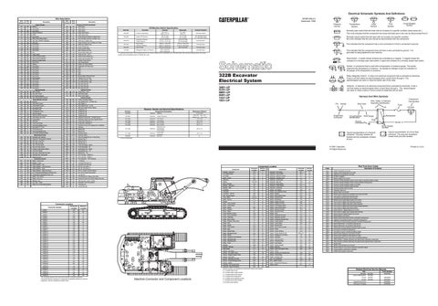
322B Excavator Electrical System
30
Connector Location
This indicates that the component has a wire connected to it that is connected to ground.
Reed Switch - A switch whose contacts are controlled by a magnet. A magnet closes the contacts of a normally open reed switch; it opens the contacts of a normally closed reed switch.
Control Circuits
Accessory Circuits
Normally closed switch that will open with an increase of a specific condition. No circle indicates that the wire cannot be disconnected from the component.
¹ A hysteresis band exists: with increasing pressure the closed condition can be maintained up to 3740 kpa (542.4 psi), with decreasing pressure the closed condition can be maintained down to 166 kpa (24.1 psi).
Lighting Circuits
Basic Machine Circuits
Normally open switch that will close with an increase of a specific condition (temp-press-etc.). The circle indicates that the component has screw terminals and a wire can be disconnected from it.
T
172
Ground Circuits
Part No.
Circuit Breaker Symbol
Flow Symbol
Level Symbol
Temperature Symbol
D = Located around relay panel. E = Located around hydraulic oil tank. F = Located around pilot manifold. G =Located under platform.
1301
Description of Problems Engine oil pressure is too low.
2201
Governor actuator feedback sensor circuit is open or shorted to battery voltage.
2202
Governor actuator feedback sensor circuit is shorted to body ground.
2301
Governor actuator feedback signal is not stable.
2302
Governor actuator feedback signal deviates.
2303
Governor actuator does not move.
2304
Calibration data error.
3201
Monitor RAM is not normal.
4101
Electric power supply to the controller is too much (43 volts).
4102
Over-current in proportional reducing valve.
4103
Proportional reducing valve circuit is open.
4104
Monitor power supply (digital output) over current.
4105
Over-current in digital output (trenching solenoid).
4106
Over-current in digital output (fine control solenoid).
4107
Over-current in digital output (travel speed change solenoid).
4108
Over-current in digital output (travel alarm).
4109
Spare solenoid 1 (digital output) over current.
410A
Over-current in digital output (swing brake solenoid).
410b
Spare solenoid 2 (digital output) over current.
4201
Engine speed is not normal.
4202
Engine coolant temperature sensor is shorted to body ground.
4203
Hydraulic oil temperature sensor is shorted to body ground.
4204
PWM sensor of pump delivery pressure is shorted to body ground.
4205
Spare PWM sensor 1 is shorted to body ground.
4206
Spare PWM sensor 2 is shorted to body ground.
4207
PWM sensor of pump delivery pressure is open in circuit.
420A
Fuel sensor is shorted to body ground
420B
Fuel sensor is open or shorted to battery voltage.
420C
Electric power supply is to low (below 23 volts).
420D
Electric power supply is to high (above 32 volts).
420E
Engine speed dial is not in one of the 10 specified positions.
4301
Data mismatch 1 between alternator and speed sensor (alternator is abnormal).
4302
Data mismatch 2 between alternator and speed sensor (speed sensor is abnormal).
4303
Engine stalls.
A201
Monitor communication is not normal.
A202
Monitor takes too much time to respond to controller’s signal.
A203
Communication is abnormal in controller.
A20d
ADEM communication disconnect.
Related Electrical Service Manuals Title
Alternator: 9W-3043
Form Number SENR3685
Electric Starting Motor: 106-8558 Consist: 106-8557 Consist: 106-8559
SENR3859 SENR3581
Engine/Pump Control:
SENR9291
Starting and Charging:
SENR9292