Electrical Schematic Symbols And Definitions Connector Location Schematic Connector Number Location
Machine Location
CONN 1
E-12
90
CONN 2
E-12
91
CONN 3
E-12
67
CONN 4
E-11
68
CONN 5
E-11
69
CONN 6
E-10
76
CONN 7
I-10
92
CONN 8
I-10
110
RD
Battery +
501
GN
Wiper - Front (Low)
103
RD
Backup
506
PU
Washer - Front
105
RD
Key Sw
508
PU
Radio Speaker - Left
107
RD
Engine Shut
509
WH
Radio Speaker - Left (Common)
109
RD
Alt Output +
511
BR
Radio Speaker - Right
112
PU
Main Power Relay Output
512
GN
Radio Speaker - Right (Common)
114
RD
Warning Horn (Forward)
521
YL
A/C Sw To Refrigerant Sw
115
RD
Chassis/Boom Lamp Relay
530
OR
Washer Right
116
BR
ATCH Cab Lamp Relay
592
BU
DC/DC Converter Power Output
117
YL
Washer/Wiper Relay
A513
PK
DC/DC Converter Memory Output
118
GY
Aux. Ckt
A579
OR
Wiper Motor +
120
YL
+24 V Ign
A580
BR
Wiper Motor -
121
YL
Back Alarm To Lamp
A581
GN
Wiper Motor Raise
124
GN
A/C
A582
PU
Wiper Motor Stop
129
BU
+24 V Switched In
A584
BU
Front Window Limit Sw To Wiper Control
135
BU
+12 V Switched Out
A588
GN
Safety Sol Relay To Sol
143
BR
Hyd Lock Timer In 1
C537
GN
A/C Photo Sensor + Sig
147
PU
Travel Spd Sol To ATCH Quick Coupler Sw
C538
OR
A/C Photo Sensor - Sig
151
GN
Neut Start Limit Sw To Hyd Lock Timer Out 1
C560
OR
Left Rear Speaker
175
RD
ATCH Heater/A/C Unit Blower
C566
PK
Left Rear Speaker (Common)
180
GN
Aux. Ckt
190
PK
One Touch Low Idle Sw
607
PK
Flood Lamp - Front
Ground Circuits
615
YL
Cab Flood Lamp/Rops
I-9
77
I-10
111
CONN 11
I-10
112
CONN 12
B-12
104
CONN 13
B-12
93
CONN 14
H-9
65
CONN 15
H-9
84
CONN 16
H-9
78
CONN 17
I-7
86
CONN 18
G-4
85
CONN 19
H-3
113
CONN 20
H-3
114
CONN 21
H-2
87
CONN 22
H-2
115
CONN 23
H-2
116
CONN 24
G-4
117
CONN 25
G-2
118
CONN 26
G-2
119
CONN 27
G-2
120
CONN 28
H-1
121
CONN 29
H-1
122
CONN 30
G-1
123
CONN 31
G-1
124
CONN 32
E-5
94
CONN 33
E-4
70
CONN 34
E-3
88
CONN 35
E-2
125
CONN 36
E-2
126
CONN 37
E-3
95
CONN 38
E-7
79
CONN 39
E-6
64
CONN 40
C-12
80
CONN 41
F-5
127
CONN 42
C-7
81
CONN 43
C-6
128
CONN 44
C-6
129
CONN 45
C-6,C-7
73
CONN 46
B-6
105
CONN 47
D-3
96
CONN 48
D-2
71
CONN 49
D-2
97
Part No.
CONN 50
C-2
98
5I-6587
CONN 51
C-3
106
CONN 52
C-3
107
CONN 53
C-3
66
CONN 54
B-2
82
CONN 55
B-3
74
B-4
83
CONN 57
A-3,A-4
130
CONN 58
A-3,A-4
131
CONN 59
A-4
108
CONN 60
A-7
99
CONN 61
B-7
89
CONN 62
B-8
100
CONN 63
B-8
101
CONN 64
B-8
102
CONN 65
C-9
72
CONN 66
A-11
132
CONN 67
A-11
133
CONN 68
B-11
109
CONN 69
B-11
103
CONN 70
C-6
75
Part No.
This indicates that the component does not have a wire connected to ground. It is grounded by being fastened to the machine.
Reed Switch - A switch whose contacts are controlled by a magnet. A magnet closes the contacts of a normally open reed switch; it opens the contacts of a normally closed reed switch.
Main Chassis
616
BU
Bucket Flood Lamp/Boom Flood Lamp
210
BK
Converter Output (24/12V)
645
PK
Head Lamp Relay
303
BR
Key Sw ACC Position
763
BU
Torque Converter Sw
304
WH
Starter Relay No. 1 Output
780
PU
Coupler Disengage Sol
306
GN
Starter Relay Coil To Neut Start Sw
E703
WH
Travel Alarm Cancel
307
OR
Key Start Sw To Neutral Start Sw
H740
OR
HEX Governor Motor +
310
PU
Start Aid Sw To Start Aid Sol
H741
WH
HEX Governor Motor -
320
RD
Horn Relay To Horn Sw
H742
PU
HEX Governor Accel Input
321
BR
Backup Alarm Lamp Travel Alarm
H744
BU
HEX Governor Low Idle
322
GY
Warning Horn (Forward)
J703
WH
Alt Pulse Sig To Anti-Start Relay
327
PK
Shutdown Sol
K776
GN
Alternator L Terminal
330
YL
Neutral Start Relay Coil
M729
PU
Governor Motor Sensor Power
332
BU
Shutdown Sw To Shutdown Control
M730
YL
Governor Motor Sensor Signal
M731
BU
Governor Motor Sensor Return
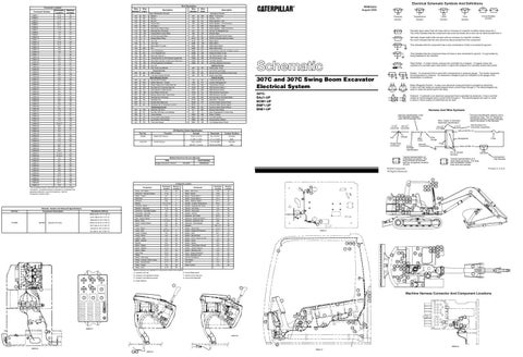
307C and 307C Swing Boom Excavator Electrical System
Control Circuits
403
GN
Alternator (R) Term.
817
WH
Backup Alarm Relay
405
GY
Opr Mon Oil Press. (Low Setting)
877
YL
Glow Plug Mag Sw To Glow Plug
439
YL
Lamp Indicator
C904
GN
Relay To Relay
441
OR
Eng Coolant Temp Gauge
N933
PU
Low Idle Indicator
442
GY
Hyd System Temp Gauge
P969
BR
Analog Return (HEDC)
447
PK
Fuel Level Gauge
R997
OR
+5V Analog Sensor Power
Off Machine Switch Specification Actuate
Engine Oil Pressure
Sender - A component that is used with a temperature or pressure gauge. The sender measures the temperature or pressure. Its resistance changes to give an indication to the gauge of the temperature or pressure.
T
Relay (Magnetic Switch) - A relay is an electrical component that is activated by electricity. It has a coil that makes an electromagnet when current flows through it. The electromagnet can open or close the switch part of the relay.
307C: BAJ1-UP BCM1-UP BMF1-UP BNE1-UP
Solenoid - A solenoid is an electrical component that is activated by electricity. It has a coil that makes an electromagnet when current flows through it. The electromagnet can open or close a valve or move a piece of metal that can do work.
Harness And Wire Symbols * Harness identification letter(s) and a serializing code. The "C" stands for connector and the number indicates which connector in the harness.
Harness identification code This example indicates wire 135 in harness "AG".
Deactuate
Contact Position
78.45 ± 9.8 kPa
49 ± 9.8 kPa
Normally
(11.38 ± 1.4 psi)
(7.1 ± 1.4 psi)
Open
1520 ± 98 kPa
1127 kPa MIN
Normally
(220.46 ± 14.2 psi)
(163.46 psi MIN)
Open
Travel Pressure
Title
Wire, Cable, or Harness Assembly Identification Part Number For L-C12* AG-C4* Connector Assembly 3E-5179 111-7898 325-A135 PK-14 1
325-A135 PK-14 Socket
Pin
Single Wire Connector
Wire Gauge
Wire Color
Receptacle
2
200-L32 BK-14
164-8231
Typical representation of a Deutsch connector. The plug contains all sockets and the receptacle contains all pins.
RENR4043
1 2
105-9344
Printed in U.S.A.
8 121 122
Component Location Component Panel - A/C Switch Governor - Actuator Engine
Resistance (Ohms)
Hydraulic Oil Temp
Schematic Location
Machine Location
D-3
20
Component Relay - Start Cont.
Schematic Location
Machine Location
H-8
40
C-12
1
Relay - Starter
G-9
41
Alarm - Travel
A-7
2
Relay - Travel Alarm 1
H-12
42
Alternator
B-11
3
Relay - Travel Alarm 2
H-11
43
Antenna
D-8
4
Relay - Washer/ Wiper
H-11
44
Battery
C-11,C-12
5
Sender - Coolant Temperature
B-12
13
Terminal - Block
F-10
21
Sender - Hydraulic Oil Temp
A-8
14
Breaker - Alternator
F-12
22
Sensor - A/C Photo
D-2
45
Governor - Controller Engine
I-9
23
Sensor - Fuel Level
A-7
15
Converter - 12V 2.5A
C-7
24
Socket - 12V 5A
C-6
46
Converter - 12V 5A
D-7
25
Solenoid - A/C Clutch
B-12
16
Dial - Engine Speed
E-3
26
Solenoid - Engine Shutdown
B-12
17
I-11,I-12
27
Solenoid - Hydraulic Lock
B-9
47
D-3
28
Solenoid - Travel Speed
B-9
48
3989-4875 @ 35 °C (95 °F)
Block - Fuse
2224-2718 @ 50 °C (122 °F)
Panel - Heater Switch
973-1189 @ 75 °C (167 °F)
Horn
A-4
6
Speaker
B-7, I-7
49
475-522 @ 100 °C (212 °F)
Lamp - Boom
A-3
7
Switch - Disconnect
D-12
18
G-1,H-1
8
Switch - Engine Oil Pressure
A-11
19
Lamp - Chassis
A-4
9
Switch - Horn
H-2
50
Lamp - Dome
H-4
29
Switch - Neutral Start
I-2
51
Lighter - Cigar
C-3
30
Switch - Ones Touch Low Idle
E-2
52
Meter - Service
C-2
31
Switch - Panel
B-3
53
Monitor
D-2
32
Switch - Starter
E-3
54
Motor - Starter
A-12
10
Switch - Travel Alarm Cancel
B-4
55
Motor - Washer
E-12
11
Switch - Travel Pressure
C-9
56
Motor - Wiper
C-2
33
Switch - Window Limit
G-3
57
Glow Plug
B-12
12
Timer - Engine Shutdown
H-9
58
Radio
C-6
34
Timer - Hydraulic Lock
I-9
59
Relay - Cab Lamp
H-11
35
Unit Air Conditioner
E-7
60
Relay - Chassis / Boom Lamp
H-12
36
Unit Heater
E-7
61
Relay - Neutral Start
H-11
37
Unit IND
E-3
62
Relay - Heater
G-9
38
Wiper Control
C-2
63
Relay - Horn
H-12
39
Lamp - Cab
Machine locations are repeated for components located close together. A Located in the cab.
E Around Relay panel.
84
B Located in the righthand console.
F Inside of Fuse relay box.
C Located in the lefthand console.
G Around Pilot Manifold.
6
5
4 117 118
94
78
119 120 7 12 13
16 93
6
9
14
108
5 80 1
2
51 87
AREA D
12 86 89 75 4
117 118
C
85
15
119 120 11 90 18
121
8
122
8
123
D
A
E
124
5 80
1
3
B
4
16 13 109 103
7 130
19 133
93
132
131
G
108 6
7
104 10
17
14 2
15 99
9
2 11 3 105
7
15 99
11 90
2
4
3 103 109
10
1
1
130 131
17 104 19 133 132
18
12
1
123 124
70
D Under Platform.
2
3
Machine Harness Connector And Component Locations
81
1 3
2
7
4 67
68
69
Component Part Number
Typical representation of a Sure-Seal connector. The plug and receptacle contain both pins and sockets.
© 2000 Caterpillar All Rights Reserved
6
91
Fuse
Plug
Ground Circuit Connection Number Identification
1 2
Form Number
Engine Governor Control
8
92
This indicates that the component has a wire connected to it that is connected to ground.
BK
65
F
Normally closed switch that will open with an increase of a specific condition. No circle indicates that the wire cannot be disconnected from the component.
Related Electrical Service Manuals
3
7
Normally open switch that will close with an increase of a specific condition (temp-press-etc.). The circle indicates that the component has screw terminals and a wire can be disconnected from it.
Lighting Circuits
Function
Circuit Breaker Symbol
Flow Symbol
Level Symbol
Temperature Symbol
Pin or Socket Number
110
5
T
Pressure Symbol
200
106-0179
221-269 @ 125 °C (257 °F)
9
Description
* * AG-C3 C-C4 130-6795 130-6795
6134-7496 @ 25 °C (77 °F)
Sender:
Wire Color
Accessory Circuits
Monitoring Circuits
20824-25451 @ 0 °C (32 °F)
4I-5394
Description
Basic Machine Circuits
Component Description
77
101
CONN 10
Resistor, Sender and Solenoid Specifications
111
Wire Color
Power Distribution Circuits
The connectors shown in this chart are for harness to harness connectors. Connectors that join a harness to a component are generally located at or near the component. See the Component Location Chart.
4
Wire Number
CONN 9
CONN 56
Wire Description Wire Number
115
76
116
14
88 13 95
9 125
126
10
106 5
72
1
97
98
73 2
17
64
96 66
100
16 79
8
AREA B
127 71
82
AREA G AREA E
AREA A 113 114
AREA C
101
3
128 129
6
AREA F
83
74
107
1
102