Wire Number
Wire Color
101
RD
103
Wire Description
Wire Color
Bat (+)
H415
BR
O.L. Warning Relay to O.L. Warning Press. SW
RD
Dome Lamp
H454
PK
O.L. Warning Relay to Diode
17.6 ± 0.6
105
BR
Key SW
H455
OR
Diode to O.L. Warning Buzzer
80.0 ± 10 @ 50 ± 0.2°C (122 ± 0.4°F) 56.3 ± 5 @ 60 ± 0.2°C (140 ± 0.4°F) 29.5 ± 2.5 @ 80 ± 0.2°C (176 ± 0.4°F) 16.5 ± 0.9 @ 100 ± 0.3°C (212 ± 0.5°F) 14.3 ± 0.5 @ 106 ± 0.5°C (223 ± 0.9°F) 10 ± 0.3 @ 120 ± 0.3°C (248 ± 0.5°F)
107
RD
Engine Shutdown
109
RD
Alt Output (+) Term.
500
BR
Wiper - Front (Park)
110
RD
Washer/Cigar Relay
501
GN
Wiper - Front (Low)
112
PU
Main Power Relay Output
506
PU
Washer - Front
113
OR
Opr Mon Panel B (+) Switched
508
PU
Radio Speaker - Left
114
RD
Warning Horn Relay (Forward)
509
WH
Radio Speaker - Left (Common)
115
RD
Chassis/Boom Lamp Relay
511
BR
Radio Speaker - Right
118
RD
Wiper Relay
512
GN
Radio Speaker - Right (Common)
121
YL
Backup Alarm
513
OR
A/C Compressor/Refrigerant Pressure SW
122
BU
Refueling Pump
519
PK
Thermostat to Refrigerant Press. SW
124
GN
A/C
A537
PK
Seat Heater SW to Seat Heater
127
RD
Cab Lamp Relay
A588
GN
Neutral Start Relay to Neutral Start SW
129
BU
Lighter
C576
BU
Switch #1 to Medium Pressure Sol #1
135
BU
12V SW Out
C577
GY
Switch #1 to Medium Pressure Sol #2
139
OR
+12V Mem Out
C588
BR
Blade SW to Blade Relay
142
BU
Solenoid
C589
GY
Blade Relay to Blade Sol
150
RD
Bat (+)
C591
PK
Floating Blade Relay to Floating Blade Sol
Power Circuits
Resistor, Sender and Solenoid Specifications
Part No.
Component Description
3E-1906
Solenoid:
096-4643
Resistance (Ohms)¹
A/C Clutch
Sender:
Hydraulic Oil Temperature
121-1491
Solenoid:
Hydraulic Lock
32.0 ± 3.2
140-0924
Resistor:
Indicator Power
300(3 sets of 2 in Parallel)
¹ At room temperature unless otherwise noted.
Part No. 5I-6587 085-5121 106-0179
Function
Off Machine Switch Specification
Engine Oil Pressure Engine Coolant Temperature
Actuate
Deactuate
Contact Position
Description Monitoring Circuits Continued
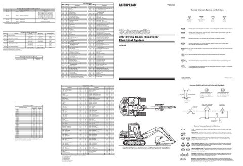
Electrical Schematic Symbols And Definitions
Accessory Circuits
Normally
151
GN
Neutral Start SW
C599
OR
Floating Blade Sw to Floating Blade Relay #2
7.1 ± 1.4 psi
Open
168
GN
Air Bleed SW
E500
YL
Blade Relay to Floating Blade Relay
106 ± 2° C
97° C
Normally
180
GN
Aux Ckt / Seat Heater SW
E501
PU
Floating Blade Relay #2 to Blade Relay
( 222.8 ± 3.6°F )
( 206.6°F MIN )
Closed
190
PK
Gov Actr
E535
GN
Swing Boom SW to Swing Boom Sol
PK
Flood Lamp - Front
Ground Circuits
Normally
( 163 psi MIN )
Open
200
BK
Main Chassis
607
275 to 1750 kPa¹
--
Normally
210
BK
Converter Output (24/12 Volt)
615
YL
Cab Flood Lamp/Rops
(40 to 255 psi)
--
Open²
616
BU
Bucket Flood Lamp/Boom Flood Lamp
20103 ± 517 kPa
18517 ± 517 kPa
Normally
303
BR
Hyd Lock Timer
633
BU
Attach Lighting Ckt
( 2915.7 ± 75 psi )
( 2685.7 ± 75psi )
Closed
135-7748
Over Load Warning Pressure
Basic Machine Circuits WH
Starter Relay No. 1 Output
306
GN
Starter Relay Coil
763
BU
Travel Speed SW to Travel Speed Sol
307
OR
Key SW to Neutral Start Relay
786
GN
Cab Light SW
² Contact position at the contacts of the harness connector.
310
PU
Start Aid SW to Start Aid Sol
791
PK
Boom Lamp SW
320
RD
Horn Relay Coil to Horn SW
792
OR
Wiper SW
321
BR
Backup Alarm Lamp Travel Alarm
799
WH
Travel Alarm Cancel SW
322
GY
Warning Horn (Forward)
B786
BU
Low Idle SW
323
WH
Fuel Pump Power
H740
OR
HEX Governor Motor +
325
PK
Fuel Pump Relay Cut-Out
H741
WH
HEX Governor Motor -
327
PK
Shutdown Solenoid
H742
PU
HEX Governor Accel Input
330
YL
Neutral Start Relay Coil
H743
YL
HEX Governor Decel Input
332
BU
Shutdown SW to Shutdown Ctrl
H744
BU
HEX Governor Low Idle
365
YL
Fuel Pump Relay to Fuel Pump SW
H745
BR
HEX Governor SW Return
J703
PK
Alt Pulse Sig to Anti-Start Relay
Title
Form Number
Electrical and Electronic Systems
RENR2978
Monitoring Circuits
This indicates that the component has a wire connected to it that is connected to ground.
GN
Alternator (R) Term.
K776
GN
Alternator L terminal
405
GY
Opr Mon Oil Press. (Low Setting)
K777
GY
Governor Pressure SW
406
PU
Opr Mon Coolant Temp
K778
WH
Hydraulic Excavator Pwr Mode SW
441
OR
Eng Coolant Temp Gauge
817
WH
Travel Alarm Timer to Travel Press SW
442
GY
Hyd System Temp Gauge
877
YL
Glow Plug Magnetic SW to Glow Plug
447
PK
Fuel Level Gauge
D813
OR
Low Idle SW HEDC
G480
GN
12 Volt (Fuel Indicator)
955
BU
Hammer Sol A
G481
WH
12 Volt (Coolant Temperature Indicator)
L976
GN
Excavator Fuel Pump SW
G482
PK
12 Volt (Hydraulic Temperature Indicator)
N933
PU
Low Idle Indicator
H414
YL
O.L. Warning Switch to O.L. Warning Relay
Schematic Location
The circle indicates that the component has screw terminals and a wire can be disconnected from it.
This indicates that the component does not have a wire connected to ground. It is grounded by being fastened to the machine.
© 2001 Caterpillar All Rights Reserved
Actuator - Engine Governor
E-2
Machine Location C
Sender - Hydraulic Oil Temp
A-6
Machine Location 19
Alarm - Over Load Warning
H-4
D
Sensor - Fuel Level
A-6
20
Alarm - Travel
A-6
1
Socket - 12V
C-2
C
Alternator
B-8
2
Solenoid - Hydraulic Lock
G-3
F
Antenna
B-1
3
Solenoid - Medium Pressure Valve
B-6
21
Assembly - Diode
F-3
C
Solenoid - A/C Compressor Clutch
C-8
22
Batteries
D-9
4
Solenoid - Blade
B-6
23
Block Assembly
F-7
E
Solenoid - Engine Pump Control
A-6
24
Breaker - Alternator
F-9
E
Solenoid - Engine Shutdown
A-8
25
Controller
D-2
5
Solenoid - Hammer
F-4
F
Converter
C-2
B
Solenoid - Travel Speed
A-6
26
Diode
J-4
A
Solenoid - Swing Boom
G-3
B
Fuse Block
J-7,8,9
E
Speakers
C-5
F
Glow Plug
C-8
6
Switch - Air Bleed
H-2
C
Ground Strap
B-8
7
Switch - Blade
F-2
C
Ground Strap
G-5
8
Switch - Blade
J-5
C
Horn
B-3
9
Switch - Blade Floating
F-2
C
Component
Schematic Location
CONN 1
E-9
E
CONN 2
E-9
E
CONN 3
E-8
E
Lamp - Boom
B-2
10
Switch - Cab Lamp
J-2
C
CONN 4
E-8
E
Lamp - Cab
E-1
11
Switch - Coolant Temperature
B-8
22
CONN 5
E-8
E
Lamp - Chassis
A-3
12
Switch - Disconnect
D-9
28
Lamp - Dome
C-5
A
Switch - Engine Oil Pressure
B-8
29
Lighter - Cigar
C-4
C
Switch - Governor Pressure
D-7
30
Meter - Service
J-2
C
Switch - Hammer
F-2
C
CONN 6
F-7
E
CONN 7
C-6
C
CONN 8
C-6
C
CONN 9
B-6
C
CONN 10
E-5
G
Monitor
C-4
34
Switch - Horn
G-1
D
CONN 11
G-4
G
Motor - Fuel Pump
A-5
13
Switch - Key Switch
E-2
C
CONN 12
G-4
G G
Switch - Lamp(Boom/Chassis)
J-1
D
G-4
A-8
14
CONN 13
Motor - Starter
CONN 14
E-4
G
Motor - Washer
E-9
15
Switch - Low Idle
F-2
C
CONN 15
E-4
G
Motor - Wiper
F-1
16
Switch - Medium Pressure
G-1
D
CONN 16
E-4
G
Multiswitch - Joystick (LH)
G-1
D
Switch - Neutral Start
J-1
C
CONN 17
E-4
G
Multiswitch - Joystick (RH)
F-2
C
Switch - Over Load Warning
J-4
D
CONN 18
A-3
17
Radio AM/FM
C-2
A
Switch - Over Load Warning Pressure
B-2
31
CONN 19
A-3
17
Relay - A/C and Heater
G-6
E
Switch - Power Mode
H-2
D
CONN 20
A-3
12
CONN 21
B-3
10
Relay - Start Cont.
H-5
E
Switch - Refrigerant Low Press
C-8
29
CONN 22
E-1
11
Relay - Blade 1
H-9
E
Switch - Refueling
A-6
20
CONN 23
E-1
11
A-6
20
CONN 25 B-3 33 The connectors shown in this chart are for harness to harness connectors. Connectors that join a harness to a component are generally located at or near the component. See the Component Location Chart.
Relay - Blade 2
H-8
E
Switch - Refueling Start
A-3
17
Relay - Blade Floating
H-7
E
Switch - Refueling Stop
A-3
17
Relay - Cab Lamp
H-8
E
Switch - Seat Heater
J-4
D
Relay - Chassis/Boom Lamp
H-9
E
Switch - Swing Boom
J-5
D
Relay - Horn
H-7
E
Switch - Swing Boom
G-1
D
Relay - Neutral Start
H-7
E
Switch - Travel Alarm Cancel
H-2
D
Relay - Over Load Warning
J-4
C
Switch - Travel Alarm Timer
J-5
E
Relay - Refueling
A-3
17
Switch - Travel Pressure
D-7
30
Relay - Refueling 2
A-2
17
Switch - Travel Speed
H-1
D
Relay - Refueling Pump
A-2
17
Switch - Washer
H-1
D
Relay - Start
G-6
E
Switch - Wiper
H-1
D
Relay - Washer/Cigar
H-8
E
Timer - Engine Shutdown
H-5
E
Relay - Wiper
J-9
E
Timer - Hydraulic Lock
H-6
E
Resistor
C-4
C
Unit - Air Conditioner
H-4
27
Seat With Heater Seat
J-2
A
Unit - Heater
H-4
32
Sender - Engine Coolant Temp
B-8
18
Machine locations are repeated for components located close together. A = Located inside of cab. B = Inside of cab, rear. C = Righthand console. D = Lefthand console. E = Located around relay panel. F = Located under platform.
Printed in U.S.A.
Harness And Wire Electrical Schematic Symbols
Component Location
Machine Location
CONN 24
Normally closed switch that is open due to an applied condition, and will close again with a specific decrease in that condition.
AFB1-UP
Schematic Location
Connector Number
Normally closed switch that will open with an increase of a specific condition.
No circle indicates that the wire cannot be disconnected from the component.
403
Component
Connector Location
307 Swing Boom Excavator Electrical System
Control Circuits
304
¹ With increasing pressure the closed condition can be maintained up to 2800 kPa (405 psi), with decreasing pressure the closed condition can be maintained down to 170 kPa (25psi).
Related Electrical Service Manuals
Normally open switch that is closed due to an applied condition, and will open again with a specific decrease in that condition.
Lighting Circuits
1127 kPa MIN
(220 ± 14psi )
Flow Symbol
Level Symbol
Normally open switch that will close with an increase of a specific condition (temp,press,etc.).
49.0 ± 9.8 kPa
1520 ± 98kPa
Temperature Symbol
Pressure Symbol
78.5 ± 9.8 kPa
Travel Pressure Refrigerant Pressure (A\C)
T
(11.4 ± 1.4 psi )
Governor Pressure
114-5333
RENR1174-01 March 2001
Wire Number
Description
A
AA
2
11 D
15 28
Typical representation of a Sure-Seal connector. The plug and receptacle contain both pins and sockets.
4 E 18 29
A
F 8
27
22
34 C
5
11 31
7 19 1
23 21
24
10
26
C
A
A 325-PK-14
12
13
Component Part Number
Single Wire Connector
33
9
14
Wire, Cable, or Harness Assembly Identification
10
30
25
Pin or Socket Number
16
32 B
3
2
6
Typical representation of a Deutsch connector. The plug contains all sockets and the receptacle contains all pins.
Receptacle
Plug
1 2
1 2
1
17
Pin
AA 1
9X-1123 325-PK-14
Wire Color
Socket
20
2
200-BK-14
Circuit Number Identification 11 3
16
Electrical Schematic Symbols And Definitions
A 10
6 28
22
14 7
18
E
15
24
2
1
27 B
21 4
34
20 19
26 23
FUSE - A component in an electrical circuit that will open the circuit if too much current flows through it.
29 30 25
13
8
REED SWITCH - A switch whose contacts are controlled by a magnet. A magnet closes the contacts of a normally open reed switch; it opens the contacts of a normally closed reed switch.
33
32 5
C
31
D 17
Wire Gauge
12 9 T
SENDER - A component that is used with a temperature or pressure gauge. The sender measures the temperature or pressure. Its resistance changes to give an indication to the gauge of the temperature or pressure. RELAY (Magnetic Switch) - A relay is an electrical component that is activated by electricity. It has a coil that makes an electromagnet when current flows through it. The electromagnet can open or close the switch part of the relay.
Machine Harness Connector And Component Locations
CIRCUIT BREAKER (C/B) - A component in an electrical circuit that will open the circuit if too much current flows through it. This does not destroy the circuit breaker and it can be reset to become part of the circuit again. SOLENOID - A solenoid is an electrical component that is activated by electricity. It has a coil that makes an electromagnet when current flows through it. The electromagnet can open or close a valve or move a piece of metal that can do work. MAGNETIC LATCH SOLENOID - A magnetic latch solenoid is an electrical component that is activated by electricity and held latch by a permanent magnet. It has two coils (latch and unlatch) that make electromagnet when current flows through them. It also has an internal switch that places the latch coil circuit open at the time the coil latches.