SENR6193 July 1994
Harness Connector Location Chart 21 7
48
40
3
4
59
58 31
8
13
A
15
12
11 A 24
13
44
22
19
15
46
CONN28
7 Contacts
25 26
51
CONN2
2
5
6
16
10 A
10 Contacts
4 32
5 A CONN1
39
28
CONN33
21 Contacts
9
37
Conn No. & Machine Location
Connector
13
43
20
14
1
9 A CONN29
12
8 A
21 22
6 Contacts
11
23
CONN10
25 A CONN26
27
29 23
17
20
9
12
CONN6
14
28 A
19
5 Contacts
CONN11
B
3
31 A
18
6
30
CONN18
24 A CONN38
4 Contacts
2 CONN39
1 CONN12
26 A CONN23
14 A CONN27
8 CONN3
12 A CONN34
13
3
CONN35
6
4
3 A
3 Contacts
5 24
2
25
15
26
1 A 27
12
CONN36
4 A CONN37
5
2 A 1
48 14
37 32 19
28
16
13
15
20
18
CONN5
2 Contacts
7
51
58 29
12
17
35 A 30 A
Schematic Location
C - 116-0125 Monitor
Conn No. & Machine Location
Connector
CONN19
E-2
C - 116-0125 B - 111-4722
18 A CONN20
C-4
C - 116-0125 A - 111-4721
17 A CONN21
C-4
C - 116-0125 Controller
16 A CONN22
E-4
Engine Governor Actuator Controller
15 A CONN24
E-4
C - 116-0125 Safety Relay
E-8
M - 101-2375 Air Conditioner Unit
F-5
C - 116-0125 G-102-7953
13 A CONN33
6 A CONN46
21 CONN46
D-9
C - 116-0125 Travel Alarm Timer
22 CONN46
E-8
C - 116-0125 Horn Relay
D-7
G - 102-7953 F - 102-7952
D-1
F - 102-7952 Wiper Motor
23 CONN49
18
2 Contacts
CONN50
3 B CONN51
F-1
C - 116-0125 Engine Shutdown Timer
2 B CONN52
D-8
C - 116-0125 Wiper Switch
E-5
C - 116-0125 Heater Unit
F-5
A - 111-4721 C - 116-0125
C-5
C - 116-0125 Work Mode Control Switch
Harness And/Or Components
17 CONN53
1 B CONN54
15 CONN55
16 CONN56
E-2
14 CONN57
C - 116-0125 Travel Speed Control Switch
E-2
C - 116-0125 Power Mode Control Switch
D-2
C - 116-0125 Cab Heater Switch
13 CONN60
34 A CONN13
D-2
C - 116-0125 Converter
D-9
C - 116-0125 H - 105-9967
D-9
27 A CONN15
Bullet Terminal
20 A CONN17
22 A
Schematic Location
C - 116-0125 Travel Alarm Cancel Switch
E-6
C - 116-0125 Cab Lamp Switch
E-6
C - 116-0125 Pump Switch
E-6
C - 116-0125 Washer Switch
E-5
C - 116-0125 Boom/Chassis Lamp Switch
E-5
C - 116-0125 Action Alarm
D-2
B - 111-4722 D - 111-4754
B-3
B - 111-4722 E - 111-4755
B-3
B - 111-4722 K - 105-9946
B-3
B - 111-4722 Fuel Level Sensor
A-6
B - 111-4722 Trenching Solenoid
A-6
B - 111-4722 Engine/Pump Control Solenoid
A-6
B - 111-4722 Travel Alarm
A-6
B - 111-4722 Travel Speed Solenoid
B-6
A - 111-4721 Pressure Switch
A-7
A - 111-4721 Travel Pressure Switch
B-7
M - 101-2375 Refrigerant Low Pressure Switch
B-7
M - 101-2375 Air Conditioner Compress Clutch Solenoid
B-8
C - 116-0125 Converter
D-8
C - 116-0125 Engine Shutdown Timer
D-8
C - 116-0125
E-8
C - 116-0125 M - 101-2375
F-8
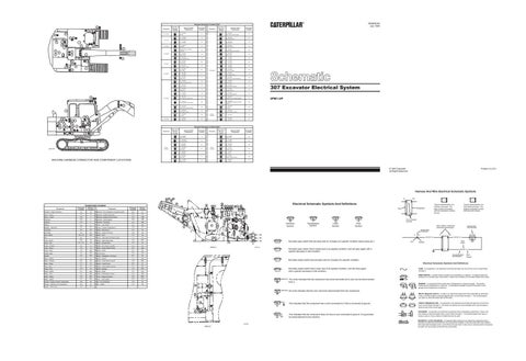
307 Excavator Electrical System 2PM1-UP
30
4 39
46
21
44
40 22 31
CONN61
Harness And/Or Components
3
19
59 8
21
22
6
9
23
Harness Connector Location Chart
23
11
14
Conn No. & Machine Location
Connector
20
43
CONN30
7 CONN31
7 A CONN40
6 CONN41
Bullet Terminal
3070778
5 CONN42
4 CONN43
3
MACHINE HARNESS CONNECTOR AND COMPONENT LOCATIONS
CONN44
27
Harness And/Or Components
Schematic Location
C - 116-0125 Horn Switch
F-3
C - 116-0125 Low Idle Switch
E-3
H - 105-9967 J - 106-0024
Conn No. & Machine Location
Connector
CONN45
24 CONN45
25 CONN45
E-1
J - 106-0024 Cab Lamp
26
F-1
J - 106-0024 Cab Lamp
F-1
E - 111-4755 Boom Lamp
CONN47
Bullet Terminal
E-1
H - 105-9967 J - 106-0024
Harness And/Or Components
20 CONN48
19 CONN58
12 CONN59
B-2
33 A
Schematic Location
E - 111-4755 Boom Lamp
B-2
E - 111-4754 Boom Lamp
B-2
P - 105-9946 Boom Lamp
B-2
B - 111-4721 Chassis Lamp
B-3
B - 111-4721 Fuel Pump
A-5
A - 111-4721 Engine Oil Press Switch
A-8
C - 116-0125 Glow Lamp
F-4
Printed in U.S.A.
© 1994 Caterpillar All Rights Reserved
Harness And Wire Electrical Schematic Symbols 52
Schematic Location
Machine Location
Actuator - Engine Governor
F-4
1A
Alarm - Action
D-2
2A
Alarm - Travel
A-6
Alternator
Schematic Location
Machine Location
Solenoid - Air Conditioner Compress Clutch
B-8
31
Solenoid - Engine Shutdown
B-9
32
3
Solenoid - Engine Pump Control
A-6
33B
B-8
4
Solenoid - Travel Speed
B-6
34B
Antenna
E-9
5
Solenoid - Trenching
A-6
35B
Battery
A-3
6
Switch - Cab Heater
E-2
36A
Breaker - Alternator
D-2
7A
Switch - Coolant Temperature
A-8
37
Controller
E-4
8A
Switch - Disconnect
A-3
38
Converter
E-8
9A
Switch - Engine Oil Press
A-8
39
E-8, F-8
10A
Switch - Horn
F-3
40
Fuse - Block Horn
B-2
11
Lamp - Boom
B-2
12
E-1, F-1
13
Lamp - Chassis
A-2
Lamp - Dome
C-5
Lamp - Glow
F-4
Lighter-Cigar Monitor Motor - Starter
A-9
Motor - Washer
B-7
Motor - Wiper
F-1
21
Plug - Glow
B-9
22
Pump - Fuel
A-5
23
Relay - Heater
E-7
24A
Relay - Horn
D-7
Relay - Safety
E-9
Relay - Starter Sender - Engine Coolant Temperature Sender - Hydraulic Oil Temperature Sensor - Fuel Level
Lamp - Cab
55
18
Component Location Component
A
45
36
Component
Switch - Light (Boom/Chassis Lamp)
F-5
41A
Switch - Light (Cab Lamp)
F-6
42A
Switch - Neutral Start
F-2
43
14
Switch - One Touch Low Idle
E-3
44
15
Switch - Power Mode Control
E-2
45A
16A
Switch - Press
A-7
46
F-5
17A
Switch-Pump
F-6
47A
E-3
18A
Switch - Refrigerant Low Press
B-7
48
19
Switch - Starter
F-4
49A
20
Switch - Travel Alarm Cancel
F-6
50A
Switch - Travel Press
B-7
51
Switch - Travel Speed Control
E-2
52A
Switch - Washer
F-5
53A
Switch - Wiper
F-5
54A
25A
Switch - Work Mode Control
E-2
55A
26A
Timer - Engine Shutdown
E-8
56A
E-7
27A
Timer - Travel Alarm
E-9
57A
B-B
28
Unit - Air Conditioner
F-5
58
B-6
29
Unit - Heater
F-4
59
A-6
30
1
49
41
16
54
2 3
Electrical Schematic Symbols And Definitions
17
1
53
47
50
42
10
AA
17
5 33
2
13
14
15
18
2
16 20
7
22
31
25
8
8
24
Pin or Socket Number
T
26
Pressure Symbol
9
7
Temperature Symbol
Level Symbol
Flow Symbol
Wire, Cable, or Harness Assembly Identification
26
25 24 10
11
56
34
28
35
C
A
A 325-PK-14
12
Normally open switch that will close with an increase of a specific condition (temp-press-etc.).
30
AREA A
Component Part Number
Single Wire Connector
27
17
Typical representation of a Sure-Seal connector. The plugand receptacle contain both pins and sockets.
57
27 6
Typical representation of a Deutsch connector. The plug contains all sockets and the receptacle contains all pins.
Receptacle
Plug
4
1 2
1 2
1
3070779
Pin
Normally open switch that is closed due to an applied condition, and will open again with a specific decrease in that condition.
AA 1
9X-1123 325-PK-14
Wire Color
Socket
2
200-BK-14
Circuit Number Identification
Wire Gauge
Normally closed switch that will open with an increase of a specific condition. Electrical Schematic Symbols And Definitions
Normally closed switch that is open due to an applied condition, and will close again with a specific decrease in that condition.
FUSE - A component in an electrical circuit that will open the circuit if too much current flows through it. REED SWITCH - A switch whose contacts are controlled by a magnet. A magnet closes the contacts of a normally open reed switch; it opens the contacts of a normally closed reed switch.
The circle indicates that the component has screw terminals and a wire can be disconnected from it. 34
T
No circle indicates that the wire cannot be disconnected from the component.
1
RELAY (Magnetic Switch) - A relay is an electrical component that is activated by electricity. It has a coil that makes an electromagnet when current flows through it. The electromagnet can open or close the switch part of the relay.
33
2
This indicates that the component has a wire connected to it that is connected to ground. 3
35
This indicates that the component does not have a wire connected to ground. It is grounded by being fastened to the machine. 3070780
AREA B
SENDER - A component that is used with a temperature or pressure gauge. The sender measures the temperature or pressure. Its resistance changes to give an indication to the gauge of the temperature or pressure.
CIRCUIT BREAKER (C/B) - A component in an electrical circuit that will open the circuit if too much current flows through it. This does not destroy the circuit breaker and it can be reset to become part of the circuit again. SOLENOID - A solenoid is an electrical component that is activated by electricity. It has a coil that makes an electromagnet when current flows through it. The electromagnet can open or close a valve or move a piece of metal that can do work. MAGNETIC LATCH SOLENOID - A magnetic latch solenoid is an electrical component that is activated by electricity and held latch by a permanent magnet. It has two coils (latch and unlatch) that make electromagnet when current flows through them. It also has an internal switch that places the latch coil circuit open at the time the coil latches.