R esist or - Def r ost Mo tor
E- 4
E
101
RD
B at (+)
441
OR
E ng Coo lant T emp G aug e
1
Blow er Mo t or
A- 12
E
102
RD
Hd Lm p
447
PK
F uel Level Ga uge
D -14
2
R esist or - P ane l L am p D i mm er
E- 9
B
103
RD
A ux Ckt
450
YL
T ac h S ender (+)
B at ter i es - 12 Volt
E- 13
5, 6
R esist or - St ar te r
E- 13
19
105
RD
K ey S w
462
YL
S eco nda ry S ter Mo tor Ind ic ator
B r eak er - A lt er nat or ( 60A)
D -13
8
Sen de r - Ar t ic u lat i on
C -12
23
108
RD
A ux Ckt
488
WH
A ir SW T o Air S W J ump er
B r eak er - C onv er te r
F -11
13
Sen de r - Co ol ant T em p.
A- 14
24
109
RD
A lt Ou tpu t (+) T erm .
498
WH
Diff . Lock Indic a tor
B r eak er - H ead la mp
D -10
B
Sen de r - F uel L evel
A- 13
25
112
PU
M ain P ower R Iy Outpu t
A 429
YL
A rticul ation Indic ator
B r eak er - L ig ht bar L ow Be am
D -10
B
Sol e noi d - A / C C lut c h
A- 13
22
113
OR
Opr Mon P anel B+ S witched
B uss B ar
E- 12
5
Sol e noi d - Bl ade Cu shi o n
E- 2
30
114
RD
Wa rnin g H orn (F orwa rd)
500
BR
Wi per - F ro nt (Park )
C ont r ol - Se con dar y St eer in g
E- 13
9
Sol e noi d - Ce nte r shi f t
C onv e rt er - 24V t o 12V
F -10
12
Sol e noi d - Di f fer en tial Unl oc k
C onv e rt er - 24V t o 12V
F -12
12
Sol e noi d - Fo rwar d H or n
D io de As - ( A/ C C lut ch Sol )
A- 13
22
F la sh er
E- 9
F us es
R esist or - Bl owe r S wit ch (H eat er )
A la rm - Ac ti on
B- 8
C
A la rm - Bac k up
E- 15
A lt er nat or
Co nn ec tor
De scrip ti on M o ni tor i ng C ir cu its (CO NT 'D )
P o wer Cir cu its
Acces so ry Cir cu its
29
115
RD
A ux Ckt
501
GN
Wi per - F ront (Lo w)
4
116
BR
A ux Ckt
502
OR
Wi per - F ro nt (HI )
F -3
10
118
GY
A ux Ckt
503
BR
Wi per - Re ar (Park )
Sol e noi d - P ar k Br ak e
B- 12
10
119
PK
A ux Ckt
504
YL
Wi per - R ear (Lo w)
B
Sol e noi d - Sh ut dow n
D -13
22
121
RD
B ack A larm T o Lamp
505
BU
Wi per - Re ar (HI)
B- 5
C
Sol e noi d - St ar t Aid
A- 13
25
122
BU
A ux Ckt
506
PU
Wa sher - F ro nt
F us es
D -9
B
Swit c h - A/ C Ref r i ge r ant
A- 12
22
123
WH
A ux Ckt
507
WH
Wa sher - R ear
F us es
E- 10
B
Swit c h - B ack - Up Ala rm
F -14
4
124
GN
508
PU
A
Swit c h - Beac on
B- 6
C
Radio S pea k er - Le ft
G aug e - US S ys t em Ai r P r es s
E- 5
A /C
129
BU
509
WH
A
Swit c h - Beac on
B- 10
C
Radio S peake r - L ef t (C omm om )
G aug e - R/ S Sy s te m Air Pr es s
E- 5
A ux Ckt
130
RD
511
BR
A
Swit c h - Bl ade Cu sh i on
B- 8
C
Radio S pea k er - Ri g ht
G aug e Clus te r
F -5
A ux Ckt
134
RD
512
GN
17
Swit c h - Bl owe r (A /C )
B- 10
C
Radio S peake r - R ig ht (C om mon )
G r ound - Cab
D -5
A ux Ckt
135
BU
513
OR
22
Swit c h - Bl owe r (H e at er)
A- 10
C
A /C Com presso r/Refrige rant Pre ss ure SW
G r ound - Eng ine
E- 12
A ux Ckt
136
GN
515
GY
39
Swit c h - B r ake A ir
A- 2
11
B lo wer M otor (HI)
G r ound - F ram e ( F r on t )
D -6
S eco nda ry St er
E- 12
8
C
PK
A ux Ckt
516
GN
B lo wer M oto r (Med ium)
Swit c h - Cent er s hi f t Pin
B- 9
141
G r ound - F ra me (Re ar)
A- 14
24
BU
Swit c h - Cool a nt
A ux Ckt
517
G r ound - Loc al ize d S tu d
D
RD
S E NR2 94 5
F -12
144
B lo wer M oto r (Low )
B- 14
24
YL
Swit c h - Cool a nt Te mp .
A ux Ckt
521
Ground Strap - Front Frame to Rear Frame
23
RD
A /C SW To Re f rig eran t S W
S E NR3 53 6 S E NR3 58 1 S E NR4 97 5
C -12
147
A
C
A ux Ckt
522
WH
Swit c h - Def r ost ( Fr ont )
A- 6
PU
L am p - M as te r Ac t ion
E- 5
149
A /C Clu tch To T h erm ostat SW
A
C
A ux Ckt
537
GN
Swit c h - Def r ost ( Rea r)
B- 6
GN
L ig ht B ar - L ow Be am
E- 8
151
T urn S ignal SW To F la she r
B
B
A ux Ckt
556
WH
Swit c h - Dif fer en tial U nlo ck
D -9
BU
M e ter - Se rv i c e M o nit or - E lec t ro nic M on it or in g Sy st e m ( E MS)
E- 10
152
Diff erent ial Lock
158
BR
A ux Ckt
570
BU
B la de Cushio n So l
E- 6
A
E- 12
6
165
YL
A ux Ckt
575
YL
Wi per - Aux (P ark)
M o tor - Bl o wer (A/ C)
B- 10
1
Swit c h - Engi n e O il
C -13
32
169
PK
A ux Ckt
576
PK
Wi per - A ux (Lo w)
M o tor - Bl o wer (He ate r )
A- 10
E
Swit c h - Flo od La mp
D -8
B
173
RD
A ux Ckt
577
PU
Wi per - Aux (H I )
M o tor - Conde ns er
B- 10
21
Swit c h - Fuel
B- 13
24
176
OR
A ux Ckt
578
BU
Wa sher - Au x
M o tor - Conde ns er
C -11
21
Swit c h - H ead la mp /T ail
E- 8
B
584
YL
Wi per SW Jum per
M o tor - Def ro st
E- 4
15
Swit c h - H ead li ght Di m mer
D -9
B
200
BK
592
BU
DC/D C Conv erter P owe r Out p ut
M o tor - Def ro st er ( Bl ow er)
A- 12
15
Swit c h - Horn
E- 9
B
201
BK
593
GN
Condensor F an Re la y To Mo t ors
M o tor - Se co nda r y St eeri ng
F -13
20
Swit c h - Hy d. O i l Te mp.
C -12
33
597
PU
A /C HI Pre s s. C outo ut SW T o Lo w P ress. SW
M o tor - St ar t er
E- 12
19
Swit c h - Ke y St art
B- 9
C
301
BU
S tart er No. 1 S ol
A 503
PK
F ront Defros t er F an (Low )
M o tor - W ash er ( Fr on t Low er )
F -6
16
Swit c h - Neut r al/ Star t
E- 14
4
304
WH
S tart er Relay No . 1 Out put
A 504
GN
Rear Defros ter F an (Low )
M o tor - W ash er ( Fr on t Up per )
F -6
16
Swit c h - P ane l La mp D im m er
E- 9
B
306
GN
S tart er Relay C oi l T o Neut St art SW Or Key SW
A 506
OR
F ront Defroste r F an (HI)
M o tor - W ash er ( Rea r)
F -6
16
Swit c h - P ar king B ra ke P r ess .
B- 11
34
307
OR
K ey St art SW T o Neut S tart SW O r Se nsor M odul e A 507
YL
Rear Def rost e r F a n (HI)
M o tor - W ip er ( F ron t Low er )
C -4
17
Swit c h - Pr i mar y St eer ing
F -10
35
308
YL
M ain P ow er Relay Coi l
A 513
PK
DC/D C Conve rter Me mory O utp ut
M o tor - W ip er ( F ron t Upper )
D -4
17
Swit c h - Sec ond ar y St e er i n g T es t
B- 8
C
310
PU
S tart A id SW T o S tart A id S ol
M o tor - W ip er ( R ear )
C -11
18
Swit c h - St ar t Ai d EM S T es t
E- 8
B
311
WH
S tart A id So l To T em p SW
600
BR
Dash Lam p Ba si c
S E NR4 13 0
S E NR4 13 0 S E NR2 08 2
Elect ronic Monit oring S yste m Starter Motor: 10 6 - 855 5 C onsist N o. 6 V -50 2 3 C onsist N o. 6 V -52 0 7 C onsist N o. 6 V -52 2 6
E
B- 3
Fo rm Nu mb er
C onsist N o. 1 0 0-5 0 46
D escri pt ion
L o cati on¹
Swit c h - Disc on ne c t
Gr o u nd Cir cu its M ain Chass is O pe rat or M onito r Return Basic M ach in e Ci r cu its
7WJ1-663
L ig h tin g Ci rc u i ts
R ec ept ic al - Au x. Sta r t
D -12
3
Swit c h - S top Lam p
A- 2
11
321
BR
B ckp A larm Lam p T rav el A larm
601
GY
Dash Lam p Hi
R el ay - C onde nse r
C -10
21
Swit c h - Ta il Lam p
D -8
B
322
GY
Wa rnin g H orn (F orwa rd)
603
PK
Rotary B eaco n
R el ay - Mai n
D -14
8
Swit c h - Tur n Signal
E- 9
B
326
RD
K ey St art SW ‘C” T erm .
604
OR
S top Lamp
R el ay - Se co nda r y St ee r ing
F -13
22
Swit c h - Wi per (F r ont L ow er )
A- 4
C
605
YL
T urn Lam p - Left
R el ay - St ar t
D -13
8
Swit c h - Wi per (F r ont U pp er )
B- 4
C
403
GN
A lt ernat or (R ) T erm .
606
GY
T urn Lam p - Rig ht
R es is to r - Bl o wer Swi t ch ( A/ C)
B- 11
15
Swit c h - W i per ( Re ar)
A- 4
C
404
YL
Opr M on Hyd Oi l T em p
608
GN
F lo od Lam p - Rea r
T her mos t at
B- 11
E
405
GY
Opr M on Oil Press . (Lo w S et ting)
609
YL
F lo od Lam p - Side
M a ch ine loc ati ons are r e pea ted f or c om pon ents loc at ed c los e t og ether .
406
PU
Opr M on Coolant T em p
611
PU
Head Lam p Hi
A = O per at or ’ s Co mpa rt m ent ( D as h) .
408
WH
Opr M on S ys tem Air P ress.
614
PU
P ark/ T ail/D ash/ L am p
B = O per at or ’ s Co mpa rt m ent ( S te eri ng C ons o le) .
409
OR
Opr Mon N eut
619
GN
Head Lam p L o
C = Oper a tor ’ s Co mpar tm ent (R ig ht S ide Co nso le) .
410
WH
Opr M on A ct ion Al arm
629
PK
A ux Head L am p
M o ni tor i ng Cir cu its
M ac hi ne Lo ca ti on
C ONN 1 Starting/C har gi ng Dia g nos t ic
E -14
45
C ONN 2
F-1 4
36
D = O pe r at or’ s C om par t men t ( Hea dli ner ) .
C ONN 3
F-1 4
7
411
PK
Opr M on M as t er
C ONN 4
B -14
8
E = O per at or ’ s Co mpa rt m ent ( U nde r Seat ) .
413
BR
Opr M on F ue l P ress.
727
GN
S eco nda ry Ste r Mo t or Re lay
C ONN 5
B -14
11
F = L oc at ed unde r c ab f loor pl ate.
415
GN
Opr M on T es t S W
728
BU
S eco nda ry Ste r Con t SW
C ONN 6
A -14
27
417
GY
P rim ary S ter S W
E 773
YL
Center Sh ift So l Pu sh
C ONN 7
A -14
26
419
YL
Opr Mon P ark ing B rak e
F 775
BU
Centers hif t S oleno id
C ONN 8
A -14
8
C ONN 9
B -13
37
C ONN 10
B -13
37
C ONN 11
B -13
37
C ONN 12
D- 13
22
C ONN 13
D- 13
37
C ONN 14
D- 13
37
16
C ONN 15
F-1 2
37
13 41 20
C ONN 16
B -12
10
C ONN 17a
A -10
C
C ONN 17b
B -11
C
C ONN 17c
A -11
C
C ONN 18
D- 12
44
C ONN 19
F-1 1
28
C ONN 20
D- 10
B
C ONN 21
D- 10
B
C ONN 22
D- 10
39
C ONN 23
D- 10
39
C ONN 24
D- 10
39
C ONN 25
C- 10
21
C ONN 26a
C- 10
33
C ONN 26b
C- 10
33
C ONN 27a
B -10
C
C ONN 27b
A -9
C
C ONN 28
B -9
38
C ONN 29
B -9
38
31 36
27
6 4
7
1 2
23
3E-79 85
17 30 29
34 11 C
10
21
39
C ONN 33
D- 8
39
C ONN 34
B -8
38
C ONN 35a Seco nd a ry S te eri n g
F-7
20
7
C ONN 35b
F-7
20
25
17
A
3T -3123 43
38 40
6T -2217
7T -9074
D- 8
C- 6
B
3E-53 83
7T -6517
C ONN 32
C ONN 38
39
18
33 37
44
42
7T -4003
39
17
8 19
28
P ar t N o.
7N-8532
39
C- 6
22
D
15
E
21
5
A -9
C ONN 37
24
26
E -9
40
18
14
D
9G-1950
28 40
E 27
24 19
8
3
41
A
B
101-175 9 C
5
6
17
33
42
32 22 37
2 1
9X-9482
9
45
26
9G-4365
15
13
16 38 12
35
39
11
43
30
6. 0 ± 3 (M IN) 92 ± 5 (M AX )
S end er - A rti culati on P osit io n S ol enoi d - E ngine Sh utdown St art (Lat c h) Coil St op (Unl at ch) Coil
1. 5 5 ± 0. 1 5 10 . 3 ± 1. 0 3
Receptacle
Plug
15 0 ± 7.5
Resisto r - S tart er/Diagnos tic Conn
10 . 0 ± 0. 5
Resisto r - D efros ter/Bl ower M otor
20 . 1 ± 1. 0
S ol enoi ds - B lade Cus hio n
* C-C4* AG-C3 130-6795 130-6795
55 . 2 ± 5. 8
S ol enoi d - F orward H ornP ark B rak e Resisto r - A /C B low er M ot or Heate r B l ower M ot or
Overall 2.0 ± .1;Tap 1.0 ±.05 6. 0
S ol enoi d - S tart Aid
68
S ol enoi d - Centers hift
14 . 4 ± 0. 6
S ol enoi d - A /C C lu tch
Pin
C- 6
17 44
C ONN 41
E -6
17
P ar t N o.
C ONN 42
E -6
17
C ONN 43
E -6
17
2M -93 46
C ONN 44
C- 5
40
C ONN 45
C- 5
40
C ONN 46
C- 5
40
C ONN 47
F-3
17
C ONN 48
F-3
17
C ONN 49
E -3
42
C ONN 50
E -3
42
C ONN 51
B -3
43
C ONN 52
D- 12
44
C ONN 53
E -12
44
C ONN 54
E -12
44
C ONN 55
E -14
3
23 34
1
Fu nct io n
3E-6425
A ct uat e
D eact uate
Conta ct Positio n
5 kP a MIN (0. 5 psi MI N )
No rmall y O pen
640 kP a (92 psi )
530 ± 4 0 kP a (77 ± 6 ps i)
No rmall y O pen
38 ± 3 °C (100 ± 5°F )
27 °C M IN (81 °F MIN)
No rmall y C lo sed
E ngi ne Coolant T em p (E MS )
107.2 ± 2.8°C (225 ± 5°F )
93. 0°C MIN (20 0°F MIN )
7N-9785
No rmall y C lo sed
8N-1693
Coolant Tem perature (St art A id)
37.8 ± 2.8°C (100 ± 5°F )
26. 7°C MIN (80 °F MIN)
No rmall y C lo sed
8N-2248
Hy draul ic Oil Tem perature
101.7°C M IN (215°F MI N)
93. 3°C MIN (20 0°F MIN )
No rmall y C lo sed
8T -8640 9W -3187 9X-0378 114-533 4
Coolant Tem perature (St art A id)
1206 kP a (M A X) (175 ps i M A X )
700 ± 1 03 k Pa (100 ± 15 psi)
A-B , Norm all y O pen A-C , Norm al ly Cl os ed
F uel Pres sure (EM S )
93 ± 21 k Pa (13.5 ± 3.0 ps i)
69 ± 2 1 k Pa (10. 0 ± 3. 0 ps i)
No rmall y C lo sed
E ngi ne Oil (P ress ure)
62 kP a (M A X) (9 p si M AX)
38 ± 2 0 k Pa (5.5 ± 3.0 p si )
No rmall y O pen
P rim ary S teeri ng Pre ssure
A /C Ref rige rant (Pressu re )
25 to 1750 kP a ¹ (40 to 255 psi )
— —
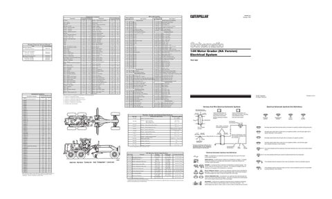
Temperature Symbol
Level Symbol
Flow Symbol
Normally open switch that is closed due to an applied condition, and will open again with a specific decrease in that condition. Harness identification code This example indicates wire 32 in harness "L'.
Normally closed switch that will open with an increase of a specific condition.
Socket
* Harness identification letter(s) and a serializing code. The "C" stands for connector and the number indicates which connector in the harness.
Normally closed switch that is open due to an applied condition, and will close again with a specific decrease in that condition.
200-L32 BK-14
2 Circuit Number Identification
Wire Color
Wire Gauge
The circle indicates that the component has screw terminals and a wire can be disconnected from it.
Electrical Schematic Symbols And Definitions
45 k Pa M A X (6.5 ps i M AX )
S top Lam p P ressure P ark B rake Ai r P ressure 3E-2033 B rake A ir Pres sure
Pressure Symbol
Normally open switch that will close with an increase of a specific condition (temp-press-etc.).
Single Wire Connector
Of f M ac h in e S w it c h S p e ci f ic at i on
20
T
9X-1123
44
D- 12
4
L-C12* 3E-5179
AG-C4* 111-7898 325-A135 PK-14
10
31
Wire, Cable, or Harness Assembly Identification
Pin or Socket Number
560 to 716 @ 54 °C (130 °F) 72 to 82 @110 °C (230 °F)
S end er - C ool ant T em pe rature
Component Part Number
2
25 . 0 ± .3
Resisto r - P anel Lam p Dim m er Swi tch
Typical representation of a Sure-Seal connector. The plug and receptacle contain both pins and sockets.
Typical representation of a Deutsch connector. The plug contains all sockets and the receptacle contains all pins.
1
Resi st ance (O hm s)¹
¹ A t room tem pera ture unless otherwise not ed.
C ONN 40
36
C omp on ent D esc ript io n
Electrical Schematic Symbols And Definitions
1 2
1 2
L-C12 * 3E-5179
AG-C4 * 111-7898
29
C ONN 39
¹ The c onnec tors sh o wn in th is ch ar t are f or ha rn ess to h arn e s s c onn e cto r s. C onnectors t hat jo in a ha rn ess to a c om pon e nt ar e gen er a lly lo ca te d at or n ear th e component . See th e Co mpo nen t L oca tion Cha rt .
Harness And Wire Electrical Schematic Symbols
R e s is t or , S e n de r a n d S o le n oi d S pe ci f ic at ions
14 35
9
32 45
C ONN 31
A -6
3
25
C ONN 30
C ONN 36
Co n tr ol Cir cu its
Part Numbers For Connector Assembly
12
Printed in U.S.A.
© 1997 Caterpillar All Rights Reserved
Sc he mat ic Lo ca ti o n
C o n ne cto r Num be r
14H Motor Grader (NA Version) Electrical System
325-L25 PK-14
9
C om po n en t
E- 14
Rela ted E lec tric al Se r vic e M anuals
Alternator (100-5 04 7 )(A tch) : C onsist N o. 1 0 0-5 0 45
Wi re Wi re N umber C olor
M ach in e L oc ati o n
M ach in e L oc ati o n
A ir D r y er
Alternator: 6N- 92 94 C ons is t No. 9 G - 457 4
Wi re Wi re N umber C olor
Sch em ati c L oc ati o n A- 11
Sch em ati c L oc ati o n F -14
C om po n en t
Tit le
RENR1441 October 1997
W ir e De s cr ip t io n
C omp onent Locatio n
No rmall y O pen ²
¹ Contact position at the contacts of the harness connector. ² A hysteresis band exists: with increasing pressure the closed condition can be maintained up to 2800 kPa (405 psi), with decreasing - pressure the closed condition can be maintained down to 170 kPa (25 psi).
FUSE - A component in an electrical circuit that will open the circuit if too much current flows through it. REED SWITCH - A switch whose contacts are controlled by a magnet. A magnet closes the contacts of a normally open reed switch; it opens the contacts of a normally closed reed switch.
T
SENDER - A component that is used with a temperature or pressure gauge. The sender measures the temperature or pressure. Its resistance changes to give an indication to the gauge of the temperature or pressure. RELAY (Magnetic Switch) - A relay is an electrical component that is activated by electricity. It has a coil that makes an electromagnet when current flows through it. The electromagnet can open or close the switch part of the relay. CIRCUIT BREAKER (C/B) - A component in an electrical circuit that will open the circuit if too much current flows through it. This does not destroy the circuit breaker and it can be reset to become part of the circuit again. SOLENOID - A solenoid is an electrical component that is activated by electricity. It has a coil that makes an electromagnet when current flows through it. The electromagnet can open or close a valve or move a piece of metal that can do work.
No circle indicates that the wire cannot be disconnected from the component.
This indicates that the component has a wire connected to it that is connected to ground.
This indicates that the component does not have a wire connected to ground. It is grounded by being fastened to the machine.