SENR6985-01 August 1995
Component Location
18 3 10
1
7
5
17
8
13 11
16
1
12
10
6
14
8
5
2
21
3
D
E
2
7
A
B
19
9
20
4
C
4
15
6
9
18
Machine Location C
Alarm - Action
Schematic Location B-8
Machine Location 10
1
Alarm - Backup
E-15
11
2
Alternator (50A standard)
D-14
3
Battery
Component
D
A
B
3
11 10
17
6
18
1
12 5
2 1
9
C
20
14
8
3
E
7 4
8
4
2
21
9
15
19
10
13
5
Wire Number
Description
Wire Color
Description Accessory Circuits (Continued)
Power Circuits 101
RD
BATTERY(+)
500
BR
WIPER - FRONT (PARK)
102
BU
HEADLAMP
501
GN
WIPER - FRONT (LO)
103
YL
AUXILIARY CKT
502
OR
WIPER - FRONT (HI)
Sender - Fuel Level
A-13
105
BR
KEY SWITCH
503
BR
WIPER - REAR (PARK)
12
Sensor - Engine Speed
B-14
107
WH
ENG SHUT - DOWN
504
YL
WIPER - REAR (LO)
C-14
13
Sensor - Transmission Speed
C-15
108
BU
AUXILIARY CKT
505
BU
WIPER - REAR (HI)
109
OR
ALT OUT (+) TERM
506
PU
WASHER - FRONT
Solenoid - A/C Clutch
A-13
112
PU
MAIN POWER RELAY OUTPUT
507
WH
WASHER - REAR
B-3
113
OR
OPR MON PANEL B+ SWITCHED
508
PU
RADIO SPEAKER - LEFT
114
GN
WARNING HORN (FORWARD)
509
WH
RADIO SPEAKER - LEFT (COMMON)
116
BR
AUXILIARY CKT
511
BR
RADIO SPEAKER - RIGHT
118
GY
AUXILIARY CKT
512
GN
RADIO SPEAKER - RIGHT (COMMON)
F-3
119
PK
AUXILIARY CKT
513
OR
A/C COMPRESSOR/REFRIGERANT PRESS SW
Component Sender - Engine Coolant Temp (gauge)
4
Battery
C-14
14
5
Breaker Alternator (60A)
D-13
15
Solenoid - Centershift
B
Breaker - Cab Flood Lamps
D-10
15
Solenoid - Differential Unlock
E-14
B
Breaker - Headlamp/Right Tail Lamp
D-10
5
Solenoid - Dual Horsepower
A-13
B
Breaker - Left Tail Lamp
D-10
15
Solenoid - Forward Horn
6
Control - Engine Shutdown
E - 13
15
Solenoid - Park Brake
B-12
122
BU
AUXILIARY CKT
515
GY
BLOWER MOTOR (HI)
6
Control - Supplement Steer
E-13
17
Solenoid - Start Aid
A-13
124
GN
AIR CONDITIONER
516
GN
BLOWER MOTOR (MEDIUM)
E
Control - Transmission
A-7
18
Solenoids - Blade Cushion
D-3
126
PK
TRANSMISSION CONTROL
517
BU
BLOWER MOTOR (LO)
130
GN
AUXILIARY CKT
521
YL
A/C SW TO REFRIGERANT SW
C
Control - Transmission Shifter
A-8
13
Solenoids - Transmission Valve (8)
C-15
134
YL
AUXILIARY CKT
522
WH
A/C CLUTCH TO THERMOSTAT SW
7
Converter - Voltage
F-10
14
Switch - A/C Refrigeration
A-13
136
GN
SUPPL STEER
537
GN
TURN SIGNAL SW TO FLASHER
B
Flasher
D-10
17
Switch - Air Dryer
F-14
141
PK
AUXILIARY CKT
556
WH
DIFFERENTIAL LOCK
Switch - Beacon
B-6
144
GN
AUXILIARY CKT
570
BU
BLADE CUSHION SOL
149
PU
AUXILIARY CKT
575
YL
WIPER - AUX (PARK)
B
Fuses
D-10
C
B
Fuses
E-11
C
Switch - Blower (A/C group)
B-10
151
GN
AUXILIARY CKT
576
PK
WIPER - AUX (LO)
C
Fuses (1OA)
B-6
C
Switch - Blower (heater group)
A-10
152
BU
AUXILIARY CKT
577
PU
WIPER - AUX (HI)
A
Gauge - Articulation
F-5
15
Switch - Brake Air Pressure
A-2
165
YL
AUXILIARY CKT
578
BU
WASHER - AUX
A
Gauge - Engine Coolant Temperature
F-5
15
Switch - Brake Air Pressure
A-2
169
PK
AUXILIARY CKT
584
YL
WIPER SW JUMPER
YL
AUXILIARY CKT
592
BU
DC/DC CONVERTER POWER OUTPUT
Gauge - Fuel Level
E-5
19
173
A
Switch - Centershift Indicator
C-3
176
OR
AUXILIARY CKT
593
GN
CONDENSER FAN RELAY TO MOTORS
A
Gauge - Speedometer
F-5
C
Switch - Centershift Pin
B-9
597
PU
A/C HI PRESS CUTOUT SW TO LOW PRESS SW
A
Gauge - Tachometer
E-5
C
Switch - Cushion Blade
B-9
A
Lamp - Action
E-5
B
Switch - Differential Unlock
D-9
Switch - Disconnect
C-14
Switch - Engine Coolant Temp
B-14
A
Lamp - Left Side Air Pressure
E-5
12
A
Lamp - Right Side Air Pressure
E-5
10
B
Meter - Service
E-10
A
Monitor - Electronic Monitoring System
E-6
Ground Circuits
12H, 140H And 160H Motor Grader (ES Version) Electrical System
(monitor) 10
Switch - Engine Coolant Temp
A-14
(start aid)
E
Motor - Blower
A-12
12
Switch - Engine Oil Pressure
C-13
E
Motor - Blower (A/C group)
B-10
B
Switch - Forward Horn
E-10
E
Motor - Blower (heater group)
A-10
C
Switch - Front Defroster
A-6
E
Motor - Blower/Defroster
E-4
C
Switch - Front Lower Wiper
A-5
8
Motor - Front Lower Washer
F-6
C
Switch - Front Upper Wiper
B-5
9
Motor - Front Lower Wiper
C-4
14
Switch - Fuel Pressure
B-13
Switch - Head/Tail Lamp
E-8 E-9
200
BK
MAIN CHASSIS
A503
PK
RONT DEFROSTER FAN (LO)
201
BK
OPR MONITOR PANEL
A504
GN
EAR DEFROSTER FAN (LO)
202
BK
TRANSMISSION CONTROL
A506
OR
RONT DEFROSTER FAN (HI)
203
BK
CHASSIS DIAGNOSTIC
A507
YL
EAR DEFROSTER FAN (HI)
207
BK
STARTER DIAGNOSTIC
A513
PK
C/DC CONVERTER MEMORY OUTPUT
276
BK
TRANSMISSION CTRL IDENT CODE 0
277
BK
TRANSMISSION CTRL IDENT CODE 1
600
BR
DASH LAMP BASIC
278
BK
TRANSMISSION CTRL IDENT CODE 2
601
GY
DASH LAMP HI
603
PK
ROTARY BEACON
Lighting Circuits
Basic Machine Circuits
8KM1-UP 6WM1-UP 2LR1-UP
301
BU
STARTER NO. 1 SOL
604
OR
STOP LAMP
302
OR
STARTER NO. 1 RESISTOR TO DIAGNOSTIC
605
YL
TURN LAMP - LEFT
304
WH
STARTER RELAY NO. 1 OUTPUT
606
GY
TURN LAMP - RIGHT
306
GN
STARTER RELAY COIL TO TRANS CONTROL
608
GN
FLOOD LAMP - REAR
307
OR
KEY SW TO TRANS CONTROL
609
YL
FLOOD LAMP - SIDE
308
YL
MAIN POWER RELAY COIL
611
PU
HEAD LAMP HI
310
PU
START AID SW TO START AID SOL
614
PU
PARK/TAIL/DASH LAMP
311
WH
START AID SOL TO TEMP SW
619
GN
HEAD LAMP LO
321
BR
BACKUP ALARM LAMP TRAVEL ALARM
629
PK
AUX HEAD LAMP
322
GY
WARNING HORN (FORWARD)
326
PU
KEY SW “C” TERM
710
GN
TRANSMISSION SPD PICKUP SIGNAL
327
PK
SHUTDOWN SOLENOID
727
GN
SUPPL STER MOTOR RELAY
334
BU
START AID SOL #2
728
BU
SUPPL STER CONT SW
373
GN
START AID SWITCH TO TIMER
751
GN
TRANS SHIFT SOL NO. 1 OR 3
Monitoring Circuits
752
YL
TRANS SHIFT SOL NO. 2
8
Motor - Front Upper Washer
F-6
B
D
Motor - Front Upper Wiper
C-4
B
Switch - Headlamp Dimmer
8
Motor - Rear Washer
F-5
20
Switch - Hydraulic Oil Temperature
C-11
D
Motor - Rear Wiper
B-11
13
Switch - Inching Pedal Pressure
C-15
5
Motor - Starter
C-13
C
Switch - Key Start
B-9
8
Motor - Supplemental Steer
F-14
B
Switch - Panel Lamp Dimmer
E-9
5
Relay - Main
D-14
15
Switch - Park Brake Pressure
B-12
403
GN
ALTERNATOR (R) TERM
754
BU
TRANS SHIFT SOL NO. 3 OR 1
B
Relay - Right Tail Lamp
E-8
21
Switch - Primary Steer Pressure
F-12
404
YL
OPR MONITOR HYD OIL TEMP
755
OR
TRANS SHIFT SOL NO. 4 OR 5
5
Relay - Start
D-13
C
Switch - Rear Defroster
B-6
405
GY
OPR MONITOR OIL PRESS (LO SETTING)
758
GN
AWD CLUTCH SW
Switch - Rear Flood Lamps
D-8
406
PU
OPR MONITOR COOLANT TEMP
795
YL
DUAL HP SOL
408
WH
OPR MONITOR SYSTEM AIR PRESS
B751
BU
ENTERSHIFT LOCK SOL
Control Circuits
8
Relay - Supplemental Steer
F-14
B
E
Resistor - Blower Speed
A-12
C
Switch - Rear Wiper
A-5
409
OR
OPR MONITOR NEUT
F769
BU
WD TO INCH PEDAL SW
E
Resistor - Blower Speed
E-4
B
Switch - Start Aid/Monitor Test
E-9
410
WH
OPR MONITOR ACTION ALARM
B899
OR
WD AGGRESSIVENESS CONT LEVER
E
Resistor - Blower Speed (A/C group)
B-11
15
Switch - Stoplamp Pressure
A-2
411
PK
OPR MONITOR ACTION LAMP
900
PU
TRANS SHIFT SOL NO. 5 OR 4
E
Resistor - Blower Speed (heater group)
A-11
B
Switch - Supplemental Steering Test
B-8
413
BR
OPR MONITOR FUEL PRESS
901
WH
TRANS SHIFT SOL NO. 6
415
GN
OPR MONITOR TEST SW
902
BR
TRANS SHIFT SOL NO. 7
B
Resistor - Panel Lamp Dimmer
E-10
B
Switch - Thermostat (A/C group)
B-11
417
GY
PRIMARY STEER SW
903
GY
TRANS SHIFT SOL NO. 8
5
Resistor - Starter/Diagnostic
C-14
B
Switch - Turn Signal
D-10
419
YL
OPR MONITOR PARKING BRAKE
921
WH
TRANS SOL NO. 1 OR 3 RETURN
7
Sender - Articulation
C-12
439
YL
LAMP INDICATOR
977
YL
CST AUTOSHIFT - AUTO/MANUAL SW 1
441
OR
ENG COOLANT TEMP GAUGE
E937
PU
G MESH CNTL - REDUNDANT NEUT
447
PK
FUEL LEVEL GAUGE
E938
OR
G MESH CNTL - FIRST GEAR
A = Operators Compartment (dash)
449
BU
SPDOM SENDER (SIGNAL NO. 1)
E939
WH
G MESH CNTL - SECOND GEAR
B = Operators Compartment (steering console)
450
YL
TACH SENDER (+)
E940
BU
G MESH CNTL - THIRD GEAR
462
YL
SUPPL STER MOTOR INDICATOR
E941
YL
G MESH CNTL - FOURTH GEAR
467
WH
SYSTEM FAULT (TRANSMISSION)
E942
GN
G MESH CNTL - FIFTH GEAR
485
YL
OPR MONITOR PANEL AWD FAULT
E943
BR
G MESH CNTL - SIXTH GEAR
488
WH
AIR SW TO AIR SW JUMPER
E944
GY
G MESH CNTL - SEVENTH GEAR
A429
YL
ARTICULATION INDICATOR
E945
PU
G MESH CNTL - EIGHTH GEAR
B426
BU
AWD HYD TEMP SENSOR
E946
OR
G MESH CNTL - FORWARD DIRECT
E947
WH
G MESH CNTL - REVERSE DIRECT
E948
BU
G MESH CNTL - PARK
E949
YL
G MESH CNTL - NEUTRAL
E975
PU
ESH LAMP
7 16
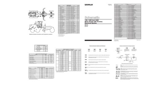
Machine Harness Connector and Component Locations
Wire Color
Schematic Location A-14
(EMS) 6
Wire Description Wire Number
Machine locations are repeated for components located close together.
C = Operators Compartment (right side console) D = Operators Compartment (headliner) E = Operators Compartment (underseat)
Printed in U.S.A.
© 1995 Caterpillar All Rights Reserved
Related Electrical Service Manuals Title
Electrical Schematic Symbols And Definitions
Form Number
Alternator (100-5047): Consist No. 100-5046 Consist No. 100-5045 Electronic Monitoring System
SENR2082 SENR4130
Electronic Transmission Shift Control
SENR6982
Starting And Charging Systems Starting Motor: (106-8555) Consist No. 6V-5207 Consist No. 6V-5023 Consist No. 6V-5226
SENR2947
A
5ENR2945
Component
SENR3581 SENR3536 SENR4975
Resistor - Starter/Diagnostic Conn
6T-2217
150.0 ± 7.5
Resistor - Power
7T-4003
10.0 ± 0.5
Resistor - Blower Speed
9G-1950
Overall 2.00 ± .10 Tap 1.00 ± .05
Solenoid - A/C Clutch
101 -1759
14.4 ± 0.6
Solenoid - Blade Cushion
7T-6517
20.1 ± 1.0
Solenoid - Centershift
8T-8808
34.3 ± 1.7
Solenoid - Dual Horsepower
8T-8610
13.5 ± 1.4
Solenoid - Differential Unlock
7T-9073
33.6 ± 1.0
Solenoid - Engine Shutdown/Dual HP
3E-6424
4.2 ± 0.4 (shutdown) 16.1 ± 0.6 (dual HP)
Solenoid - Forward Horn/Park Brake
7T-9074
55.17 ± 5.77
Solenoid - Start Aid
9G-4365
6.0
Solenoids - Transmission
127-0574
31.0 ± 3.0
¹ At room temperature unless otherwise noted.
Off Machine Switch Specification 2M-9346
Stop Lamp Pressure
3E-2033
Brake/Park Brake Air Pressure
7N-9785
Engine Coolant Temperature
8N-1693
Engine Coolant Temp (start aid)
8N-2248
Hydraulic Oil Temperature
8T-8640
Primary Steering Pressure
9W-3187
Fuel Pressure
Actuate
Deactuate
45.0 kPa Max (6.5 psi Max) 640 kPa MAX (92.0 psi MAX) 107.2 ± 2.78°C (225.0 ± 5.0°F) 37.8 ± 2.8°C (100 ± 5°F) 101.7 ± 2.8°C (215.0 ± 5.0°F) 1206 kPa MAX (175 psi MAX) 93.0 ± 20.8 kPa (13.5 ± 3.0 psi)
5.0 kPa MIN (0.5 psi MIN) 530 ± 40 kPa (77.0 ± 6.0 psi) 93.0°C MIN (199.4°F MIN) 26.7°C MIN (80.0°F MIN) 93.3°C MIN (200.0°F MIN) 700 ± 50 kPa (100 ± 7 psi) 69 ± 21 kPa (10 ± 3 psi)
Contact Position Normally Open Normally Open Normally Open Normally Closed Normally Closed Normally Closed Normally Closed
62.0 kPa MAX 38 ± 20 kPa Engine Oil Pressure 9X-0378 Normally Open (9.0 psi MAX) (5.5 ± 3.0 psi) 75.0 kPa MAX 50.0 kPa MIN Inching Pedal Pressure 111-7088 Normally Open (10.9 psi MAX) (7.3 psi MIN) 275 to 1750 kPa¹ — Refrigerant Pressure (A/C) 114-5334 Normally Open² — (40 to 255 psi) ¹ A hysteresis band exists: with increasing pressure the closed condition can be maintained up to 2800 kpa (405 psi), with decreasing pressure the closed condition can be maintained down to 170 kpa (25psi). ² Contact postion at the contacts of the harness connector.
Schematic Location
G - 106-1319 A-7 Transmission Control G - 106-1319 24 Contacts * A-8 Transmission Shifter Sw AAA - 123-4617 1 E-14 Diagnostic Connector 20 Contacts M - 115-9436 * E-6 Monitor (EMS) A - 115-9367 2 D-12 C - 115-9425 A - 115-9367 2 D-11 J - 115-9430 A - 115-9367 2 E-9 J - 115-9430 A - 115-9367 10 Contacts 3 C-6 K - 115-9432 A - 115-9367 3 E-6 M - 115-9436 F - 101-8168 5 C-15 N - 9U-9313 K - 115-9432 C-5 6 L - 115-9433 A - 115-9367 2 E-12 C - 115-9425 A - 115-9367 2 F-12 C - 115-9425 A - 115-9367 7 B-12 E - 115-9426 A - 115-9367 9 Contacts 3 E-6 M - 115-9436 A - 115-9367 4 B-9 U - 116-2306 G - 106-1319 C B-7 Service Tool Connector M - 115-9436 * F-6 Gauge Cluster C - 115-9425 8 B-13 AAA - 123-4617 C - 115-9425 8 B-13 AAA - 123-4617 8 Contacts K - 115-9432 7 F-11 Radio H - 101-8161 6 A6 L - 115-9433 * = Connector is located at the component. See component location chart. Machine locations are repeated for connectors located close together C = Operators compartment (Right side console) 40 Contacts
Resistance (Ohms)¹
Harness And/Or Components
Connectors
*
Machine Location 9 9 2 6 3 2
7 Contacts 4 8 8 4 4 6 10 6 Contacts * 2 5 Contacts
4 * C *
4 Contacts
* * *
Harness And/Or Components
A - 115-9367 G - 106-1319 A - 115-9367 G - 106-1319 A - 115-9367 J - 115-9430 A - 115-9367 K - 115-9432 A - 115-9367 M - 115-9436 A - 115-9367 P - 115-9439 A - 115-9367 U - 116-2306 Y - 116-2867 AAA - 123-4617 C - 115-9425 Y - 116-2867 F - 101-8168 G - 106-1319 F - 101-8168 G - 106-1319 K - 115-9432 L - 115-9433 E - 115-9426 CCC - 15-9448 A - 115-9367 Voltage Converter A - 115-9367 J - 115-9430 A - 115-9367 U - 116-2306 U - 116-2306 AC/Heater Unit G - 106-1319 G - 106-1319 A - 115-9367 Centershift Switch A - 115-9367 Front Lower Wiper H - 101-8161 Rear Wiper K - M115-9432Front Upper Wiper
Schematic Location B-7
T
Pressure Symbol
Temperature Symbol
Typical representation of a Deutsch connector. The plug contains all sockets and the receptacle contains all pins.
Receptacle
Plug
Level Symbol
Flow Symbol
1 2
1 2
HARNESS CONNECTOR LOCATION CHART Machine Connectors Location
Part No.
Function
AA 1
Resistor, Sender and Solenoid Specifications
Part No.
Harness And Wire Electrical Schematic Symbols
2
Typical representation of a Sure-Seal connector. The plugand receptacle contain both pins and sockets.
B-7
Pin or Socket Number
D-8 C-6 E-6
Wire, Cable, or Harness Assembly Identification
Normally open switch that will close with an increase of a specific condition (temp-press-etc.).
Single Wire Connector
F-3 B-8 E-13
C
Normally open switch that is closed due to an applied condition, and will open again with a specific decrease in that condition. Pin
Normally closed switch that will open with an increase of a specific condition.
AA 1
C-5
9X-1123 325-PK-14
Wire Color
Socket
2
E-12
F-14
A
A 325-PK-14
B-13 E-12
Component Part Number
200-BK-14
Circuit Number Identification
Normally closed switch that is open due to an applied condition, and will close again with a specific decrease in that condition.
Wire Gauge
F-11
Electrical Schematic Symbols And Definitions
D-8 B-9
The circle indicates that the component has screw terminals and a wire can be disconnected from it.
FUSE - A component in an electrical circuit that will open the circuit if too much current flows through it.
A-11
REED SWITCH - A switch whose contacts are controlled by a magnet. A magnet closes the contacts of a normally open reed switch; it opens the contacts of a normally closed reed switch.
A-8 C-3
No circle indicates that the wire cannot be disconnected from the component.
C-4 B-11 C-4
T
SENDER - A component that is used with a temperature or pressure gauge. The sender measures the temperature or pressure. Its resistance changes to give an indication to the gauge of the temperature or pressure.
This indicates that the component has a wire connected to it that is connected to ground. RELAY (Magnetic Switch) - A relay is an electrical component that is activated by electricity. It has a coil that makes an electromagnet when current flows through it. The electromagnet can open or close the switch part of the relay.
This indicates that the component does not have a wire connected to ground. It is grounded by being fastened to the machine.
CIRCUIT BREAKER (C/B) - A component in an electrical circuit that will open the circuit if too much current flows through it. This does not destroy the circuit breaker and it can be reset to become part of the circuit again. SOLENOID - A solenoid is an electrical component that is activated by electricity. It has a coil that makes an electromagnet when current flows through it. The electromagnet can open or close a valve or move a piece of metal that can do work. MAGNETIC LATCH SOLENOID - A magnetic latch solenoid is an electrical component that is activated by electricity and held latch by a permanent magnet. It has two coils (latch and unlatch) that make electromagnet when current flows through them. It also has an internal switch that places the latch coil circuit open at the time the coil latches.