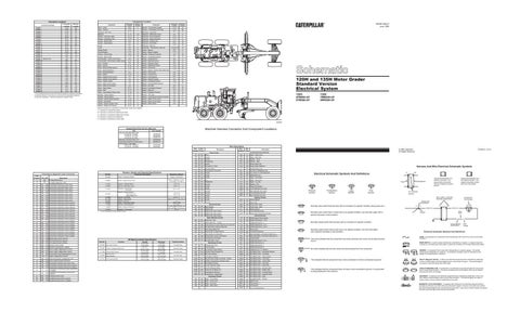
Connector Location¹ Connector Number CONN 1 CONN 2 CONN 3 CONN 4 CONN 5 CONN 6 CONN 7 CONN 8 CONN 9 CONN 10 CONN 11 CONN 12 CONN 13 CONN 14 CONN 15 CONN 16 CONN 17 Service Tool CONN 18 CONN 19 CONN 20 CONN 21 CONN 22 CONN 23 CONN 24 CONN 25 CONN 26 CONN 27 CONN 28 CONN 29 CONN 30 CONN 31 CONN 32 CONN 33 CONN 34
Schematic Location C-15 E-15 E-15 F-14 A-14 B-13 B-13 D-13 D-13 B-12 A-11 D-10 D-10 D-10 A-9 A-9 A-9 B-9 E-9 E-9 B-8 B-8 E-6 E-6 C-6 C-6 C-6 A-6 C-5 C-5 B-3 E-3 F-3 F-3
Machine Location 26 26 26 6 5 29 29 30 29 25 C B 23 23 10 10 C 25 B B 10 10 24 24 24 27 27 27 27 27 15 23 23 23
¹ The connectors shown in this chart are for harness to harness connectors. Connectors that join a harness to a component are generally located at or near the component. See the Component Location Chart.
Schematic Location
Component
Component Location Machine Location
Schematic Location
Sender - Transmission Speed
D-15
Machine Location
Sensor - Transmission Oil Temp
E-15
26 16
Component
Alarm - Action
B-8
Alarm - Backup
F-15
1
Alternator (35A STD)
D-14
2
Solenoid - Centershift
B-3
Batteries
C-14
3,4
Solenoid - Differential Unlock
E-4
17
Breaker - Alternator (35A)
D-1 3
5
Solenoid - Dual Horsepower
A-13
5
Breaker - Headlamp (15A)
D-10
B
Solenoid - Engine Shutdown
D-13
5
Control - Neutral Start
B-9
10
Solenoid - Forward Horn
A-3
16
Control - Transmission
A-7
E
Solenoid - Park Brake
B-12
16
Fuses
B-6
C
Solenoid - Start Aid
A-13
18
Fuses
D-9
B
Solenoids - Transmission Valve (8)
D-15,E-15
14
Gauge Cluster
F-5
A
Switch - Beacon
B-6
C
Ground-Engine
C-13
12
Switch - Blower (Heater)
A-10
C
Ground - Front Frame
D-6
21
Switchs - Brake Air Pressure
A-2
16
Ground - Rear Frame
C-13
28
Switch - Centershift Indicator
B-3
19
Ground Strap - Cab to Front Frame
D-6
24
Switch - Centershift Pin
B-9
C
C-12
20
Switch - Defroster (Front)
A-6
C
Horn - Forward
F-3
16
Switch - Defroster (Rear)
B-6
C
Meter - Service
E-10
B
Switch - Differential Unlock
D-8
B
Motor - Blower (Heater group)
A-10
E
Switch - Disconnect
C-14
13
Motor - Blower/Defroster
A-11
E
Switch - Engine Coolant Temp (Start Aid)
A-14
11
Motor - Blower/Defroster
E-4
E
Switch - Flood Lamp
D-8
B
Motor - Starter
C-13
5
Switch - Forward Horn
E-9
B
Motor - Washer (Front Lower)
F-6
8
Switch - Fuel Pressure
B13
13
Motor - Washer (Front Upper)
F-6
8
Switch - Head/Tail Lamp
E-8
B
Motor - Washer (Rear)
F-6
8
Switch - Headlamp Dimmer
E-9
B
Motor - Wiper (Front Lower)
C-4
9
Switch - Inching Pedal Pressure
C-15
14
Motor - Wiper (Front Upper)
D-4
0
Switch - Key Start
B-9
C
Motor - Wiper (Rear)
B-11
0
Switch - Park Brake Pressure
B-11
16
Relay - Start
D-13
5
Switch - Start Aid
E-8
B
Relay - Transmission Action Lamp
C-10
8
Switch - Stoplamp Pressure
A-2
16
Resistor - Blower Speed
A-12
E
Switch - Tail Lamp
D-8
B
Resistor - Blower Speed
E-4
E
Switch - Transmission Direction & Speed
A-8
C
Resistor - Blower Speed (Heater)
A-10
E
Switch - Wiper (Front Lower)
A-5
C
Sender - Articulation
C-12
7
Switch - Wiper (Front Upper)
B-5
C
Sender - Engine Coolant Temp
A-14
11
Switch - Wiper (Rear)
A-5
C
Sender - Engine Oil Pressure
B-14
13
Ground Strap - Front Frame to Rear Frame
C
RENR1426-01 June 1998
14
1
B = Operator’s compartment (Steering console).
12
2 5
11
17
7
29 30
21
D
E
20
23 B
C 10 25 27
9 A
19
24 1615
120H and 135H Motor Grader Standard Version Electrical System
27 D
120H: 5FM800-UP 6TM366-UP
A 22
C
12
13 5
4 3 29
2
B
11
18
6 14 26
A = Operator’s compartment (Dash).
22 13
8
4
1
Machine locations are repeated for components located close together.
3
6 26 18 14
30 20
28
8 25 10 21
24 15 23 16
19
7
17
C = Operator’s compartment (Right side console).
E
9
135H: 7MM249-UP 8WN350-UP
D= Operator’s compartment (Headliner). E = Operator’s compartment (Under seat).
E20367
Machine Harness Connector And Component Locations
Related Electrical Service Manuals
Title Alternator (6N-9294 35A): STD Consist No. 3T-6352 Consist No. 7N-9720 Consist No. 9G-4574
Form Number SENR4978 SENR2082 SENR4130
Alternator (100-5047 50A): ATT
SENR2082
Transmission Electronic Shift Control Starting Motor: (106-8558) Consist No. 106-8557 Consist No. 106-8559
SENR91 67 SENR3559 5ENR3581 Wire Number
Wire Color
101
RD
102
BU
103
Wire Description Wire Number
Wire Color
Bat(+)
504
YL
Wiper - Rear (Low)
HdLmp
505
BU
Wiper - Rear (Hi)
RD
AuxCkt
506
PU
Washer - Front
105
RD
Key Start Sw
507
WH
Washer - Rear
108
BU
AuxCkt
515
GY
Blower Motor (Hi)
109
OR
Alt Output (+) Term.
516
GN
Blower Motor (Medium)
113
RD
Opr Mon Panel
517
BU
Blower Motor (Low)
114
RD
Warning Horn (Forward)
521
YL
A/C SW To Refrigerant SW
116
RD
AuxCkt
522
WH
A/C Clutch To Thermostat SW
118
GY
AuxCkt
556
WH
Differential Lock
Description Power Circuits
Code Flashed 11
Transmission Diagnostic Code Conversion
12
CID - FMI Description N/A No diagnostics active N/A No logged diagnostic codes
21
641
22
642
23
643
24
644
25
645
26
646
27
647
28
648
31
641
32
642
33
643
34
644
35
645
36
646
37
647
38
648
41
641
42
642
43
643
44
644
Resistor, Sender and Solenoid Specifications
Part No. 3E-5383
Component Description
Sender - Articulation Position
Resistance (Ohms)¹
Accessory Circuits (Continued)
Range - 3 to 97 Ohms
119
PK
AuxCkt
575
YL
Wiper - Aux (Park)
560 to 716 @ 54°C (1 30°F) 72 tO 82 @ 110°C(230°F)
124
RD
A/C
576
PK
Wiper - Aux (Low)
7N-8532
Sender - Engine Coolant Temp
126
PK
XMSNCTRL
577
PU
Wiper - Aux (Hi)
F05 Transmission Solenoid A open circuit F05 Transmission Solenoid B open circuit
7T-4003
Resistors - Defroster Blower
10.0 ± 0.5
129
BU
578
BU
7T-9073
Solenoid - Differential Unlock
33.6 ± 1.0
Aux Ckt
Washer - Aux
130
RD
AuxCkt
584
YL
Wiper SW Jumper
F05 Transmission Solenoid C open circuit F05 Transmission Solenoid D open circuit
7T-9074
Solenoids - Forward Horn Park Brake
55.17 ± 5.77
135
BU
AuxCkt
A503
PK
Front Defroster Fan (Low)
F05 Transmission Solenoid E open circuit F05 Transmission Solenoid F open circuit
8C-3663 8T-8808 9G-1 950 9G-4365 104-6387 111-0570
F05 Transmission Solenoid G open circuit F05 Transmission Solenoid H open circuit F06 Transmission Solenoid A short to ground F06 Transmission Solenoid B short to ground F06 Transmission Solenoid C short to ground F06 Transmission Solenoid D short to ground F06 Transmission Solenoid E short to ground F06 Transmission Solenoid F short to ground
116-9937
Solenoid - Engine Shutdown Start (Latch) Coil Stop (Unlatch) Coil Solenoid - Centershift Resistor - Blower Speed Solenoid - Start Aid Sender - Transmission Speed Solenoid - Dual Horsepower Sender - Engine Oil Pressure
127-0574 Solenoids - Transmission ¹ At room temperature unless otherwise noted.
141
PK
Aux Ckt
A504
GN
Rear Defroster Fan (Low)
1.55 ± 0.15 10.3 ± 1.03
144
GN
Aux Ckt
A506
OR
Front Defroster Fan (Hi)
149
RD
AuxCkt
A507
YL
34.3 ± 1.7 Overall 2.00 ± .10 Tap 1.00 ± .05 6 1000 to 1200 31.1 ± 2.4 21.5-49.5 @552 kPa (80.1 psi) 227 - 257 @ 21 kPa (3.0 psi) 31 ± 3
151
GN
AuxCkt
Rear Defroster Fan (Hi) Lighting Circuits
152
BU
AuxCkt
603
PK
Rotary Beacon
165
RD
Aux Ckt Ground Circuits
604
OR
Stop Lamp
608
GN
Flood Lamp - Rear
201
BK
Main Chassis
609
YL
Flood Lamp - Side
202
BK
XMSN CTRL
611
PU
Head Lamp Hi
276
BK
XMSN CTRL Ident Code 0
614
PU
Park/Tail/Dash/Lamp
277
BK
XMSN CTRL Ident Code 1
619
GN
278
BK
XMSN CTRL Ident Code 2 Basic Machine Circuits
Head Lamp LowControl Circuits Control Circuits
710
GN
XMSN Speed Pickup Signal
301
BU
Starter No. 1 Sol
751
GN
XMSN Shift Sol No. 1 Or 3
304
WH
Starter Relay No. 1 Output
752
YL
XMSN Shift Sol No. 2
306
GN
Starter Relay Coil To Neut Start SW Or Key Start SW
754
BU
XMSN Shift Sol No. 3 Or 1
307
OR
Key Start SW To Neutral Start SW
755
OR
XMSN Shift Sol No. 4 Or 5
308
YL
YL
Dual Hp Sol
F06 Transmission Solenoid G short to ground F06 Transmission Solenoid H short to ground F03 Transmission Solenoid A short to battery F03 Transmission Solenoid B short to battery F03 Transmission Solenoid C short to battery F03 Transmission Solenoid D short to battery
45
645
F03 Transmission Solenoid E short to battery
Main Power Relay Coil
795
46
646
F03 Transmission Solenoid F short to battery
310
PU
Start Aid SW To Start Aid Sol
F775
BU
Centershift Solenoid
47
647
F03 Transmission Solenoid G short to battery
311
WH
Start Aid Sol To Temp SW
892
BR
Start Mod Right (-) Port/CAT Data Link (-)
48
648
F03 Transmission Solenoid H short to battery
321
BR
Backup Alarm Lamp Travel Alarm
893
GN
Start Mod Right (+) Port/CAT Data Link (+)
52
637
F06 Backup alarm short to ground
322
GY
Warning Horn (Forward)
F843
YL
Inching Pedal
58
688
F06 VHP solenoid short to ground
326
PU
PU
XMSN Shift Sol No. 5 or 4
688
F03 VHP solenoid short to battery
Key Start SW C Term. Monitoring Circuits
900
59
901
WH
XMSN Shift Sol No. 6
61
668
F02 Shift lever input invalid
GN
Alternator (R) Term.
902
BR
XMSN Shift Sol No. 7
62
668
F03 Shift lever open/short to +battery
439
YL
Lamp Indicator
903
GY
XMSN Shift Sol No. 8
441
OR
Eng Coolant Temp Gauge
921
WH
XMSN Sol No 1 Or 3 Return
460
WH
Opr Mon Panel Program Pin
E937
PU
MG MESH CNTL - Redundant Neutral
63
269
F00 Sensor supply voltage above normal
64
269
F01 Sensor supply voltage below normal
65
701
F02 Transmission output speed signal incorrect
68
168
F01 System voltage below normal
71
520
F02 Invalid transmission configuration code
72
268
F02 Check programmable parameters
73
764
74
764
75
Part No.
Function
2W-9346
Stop Lamp Pressure
8C-3569
Coolant Temperature (Start Aid)
111-7088
Inching Pedal Pressure
112-2024
Brake Air Park Brake Pressure
115-7103
Fuel Pressure (EMS)
Off Machine Switch Specification Actuate
45 kPa MAX (6.5 psi MAX) 38 ± 3°C (100.4° ± 5.4°F) 75.0 kPa MAX (10.9 psi MAX) 640 kPa MAX (92.0 psi MAX) 93 ± 21 kPa (13.5 ± 3.0 psi)
Deactuate
5 kPa MIN (0.5 psi MIN) 27 °C MIN (80.6°F MIN) 50.0 kPa MIN (7.3 psi MIN) 530 ± 40 kPa (77.0 ± 6.0 psi) 69 ± 21 kPa (10.0 ± 3.0 psi)
Contact Position Normally Open Normally Closed Normally Open
403
498
WH
Diff. Lock Indicator
E938
OR
MG MESH CNTL - First Gear
A429
YL
Articulation Indicator
E939
WH
MG MESH CNTL - Second Gear
A476
PU
Eng Oil Press Gauge To Sender - Eng #1
E940
BU
MG MESH CNTL - Third Gear
B476
BU
(NFND) Transmission Indicator Lamp
E941
YL
MG MESH CNTL - Fourth Gear
F05 Transmission indicator lamp open circuit
C491
PU
Park Brake Pressure
E942
GN
MG MESH CNTL - Filth Gear
F06 Transmission indicator lamp short to ground
E458
YL
Low Air Pressure Lamp
E943
BR
MG MESH CNTL - Sixth Gear
764
F03 Transmission indicator lamp short to battery
E459
WH
Low Air Pressure Alarm
E944
GY
MG MESH CNTL - Seventh Gear
76
177
E460
BR
Trans Cntl To Relay Coil
E945
PU
MG MESH CNTL - Eighth Gear
77
762
F03 to +battery Transmission oil temperture switch short F04 to ground
F473
YL
Transmission Warning
E946
OR
MG MESH CNTL - Forward Direct
81
868
GN
WH
MG MESH CNTL - Reverse Direct
868
Transmission Temperature Accessory Circuits
E947
82
F05 Auto/Manual lamp open F06 Auto/Manual lamp short to ground
G460
E948
BU
MG MESH CNTL - Park
83
868
F03 Auto/Manual lamp short to +battery
Transmission oil temperature signal Open/Short
Normally Open Normally Closed
500
BR
Wiper - Front (Park)
E949
YL
MG MESH CNTL - Neutral
501
GN
Wiper - Front (Low)
E975
PU
MESH Lamp
502
OR
Wiper - Front (Hi)
M917
PK
TOS Sensor +
503
BR
Wiper - Rear (Park)
M91 8
PK
TOS Sensor
M998
OR
Xmsn Autoshift Mode
Printed in U.S.A.
© 1998 Caterpillar All Rights Reserved
Description
Harness And Wire Electrical Schematic Symbols A
Electrical Schematic Symbols And Definitions
AA
Typical representation of a Deutsch connector. The plug contains all sockets and the receptacle contains all pins.
Receptacle
Plug
1 2
1 2
1
2
Typical representation of a Sure-Seal connector. The plugand receptacle contain both pins and sockets.
T
Pressure Symbol
Temperature Symbol
Level Symbol
Flow Symbol
Pin or Socket Number Wire, Cable, or Harness Assembly Identification
Component Part Number
Single Wire Connector
Normally open switch that will close with an increase of a specific condition (temp-press-etc.).
C
A
A 325-PK-14
Pin
Normally open switch that is closed due to an applied condition, and will open again with a specific decrease in that condition.
AA 1
Wire Color
Socket
2
Normally closed switch that will open with an increase of a specific condition.
Wire Gauge
Electrical Schematic Symbols And Definitions FUSE - A component in an electrical circuit that will open the circuit if too much current flows through it.
The circle indicates that the component has screw terminals and a wire can be disconnected from it.
REED SWITCH - A switch whose contacts are controlled by a magnet. A magnet closes the contacts of a normally open reed switch; it opens the contacts of a normally closed reed switch.
No circle indicates that the wire cannot be disconnected from the component. T
This indicates that the component does not have a wire connected to ground. It is grounded by being fastened to the machine.
200-BK-14
Circuit Number Identification
Normally closed switch that is open due to an applied condition, and will close again with a specific decrease in that condition.
This indicates that the component has a wire connected to it that is connected to ground.
9X-1123 325-PK-14
SENDER - A component that is used with a temperature or pressure gauge. The sender measures the temperature or pressure. Its resistance changes to give an indication to the gauge of the temperature or pressure. RELAY (Magnetic Switch) - A relay is an electrical component that is activated by electricity. It has a coil that makes an electromagnet when current flows through it. The electromagnet can open or close the switch part of the relay. CIRCUIT BREAKER (C/B) - A component in an electrical circuit that will open the circuit if too much current flows through it. This does not destroy the circuit breaker and it can be reset to become part of the circuit again. SOLENOID - A solenoid is an electrical component that is activated by electricity. It has a coil that makes an electromagnet when current flows through it. The electromagnet can open or close a valve or move a piece of metal that can do work. MAGNETIC LATCH SOLENOID - A magnetic latch solenoid is an electrical component that is activated by electricity and held latch by a permanent magnet. It has two coils (latch and unlatch) that make electromagnet when current flows through them. It also has an internal switch that places the latch coil circuit open at the time the coil latches.