Wire Number
Wire Color
101
RD
102
Wire Description
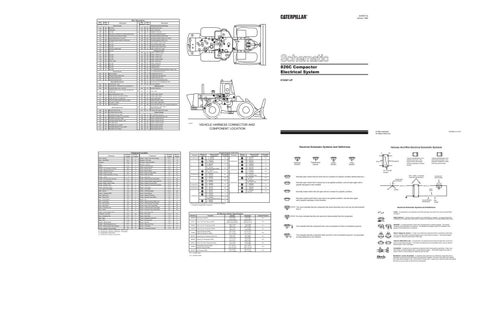
SENR4732 January 1990
Wire Number
Wire Color
BATTERY
415
GN
OPR MON TEST SW
BU
HEADLAMP
416
OR
SUPPL STER SW
105
BR
KEY SW
417
GY
PRIMARY STER SW
107
WH
ENG SHUT -DOWN/AUTO FIRE SUPPR CONT
419
YL
OPR MON PARKING BRAKE
109
OR
ALTERNATOR OUTPUT(+)TERM.
424
GY
OPR MON POWER TRAIN TEMP
112
PU
MAIN POWER RELAY OUTPUT
426
BR
OPR MON POWER TRAIN OIL FILTER
Description
Description Monitoring Circuits (Continued)
Power Circuits
113
OR
OPR MON PANEL/VMIS B+ SWITCHED
432
PK
OPR MON BRAKE PRESS. (OIL)
116
BR
AUX CKT
441
OR
ENG COOlANT TEMP GAGE
118
GY
AUX CKT
442
GY
9
18
HYD SYSTEM TEMP GAGE
AUX CKT
443
YL
POWER TRAIN TEMP GAGE
YL
BACKUP ALARM/LAMP
453
PK
SUPPL STER FAULT lAMP
123
WH
AUX CKT
124
GN
A/C
500
BR
WIPER - FRONT (PARK)
127
OR
AUX CKT
501
GN
WIPER - FRONT (LO)
128
PK
AUX CKT
502
OR
WIPER - FRONT (HI)
129
BU
AUX CKT
503
BR
WIPER - REAR (PARK)
136
GN
SUPPL STER
504
YL
WIPER - REAR (LO)
148
WH
AUX CKT
505
BU
WIPER - REAR (HI)
158
BR
AUX CKT
506
PU
WASHER-FRONT
176
OR
AUX CKT
507
WH
WASHER-REAR
176
YL
AUX CKT
513
OR
A/C COMPRESSOR/REFRIGERANT PRESS. SW
514
PU
A/C CONDENSER MOTOR
200
BK
MAIN CHASSIS
515
GY
BLOWER MOTOR (HI)
201
BK
OPRMON PANEL/VMIS/CMS
516
GN
BLOWER MOTOR (MEDIUM)
203
BK
CHASSIS DIAGNOSTIC
517
BU
BLOWER MOTOR (LO)
207
BK
STARTER DIAGNOSTIC
521
YL
A/C SW TO REFRIGERANT SW
522
WH
A/C CLUTCH TO THERMOSTAT SW
567
WH
A/C SW JUMPER
Basic Machine Circuits
6
8
17 20
11
21
B
22
3
25
28
9
10
D
13
5
19 14 10
2
Accessory Circuits
C
2
26
24 15
27
PK
121
Ground Circuits
6
7 1
119
7
12
1
4
8
A
5
3 16
29
826C Compactor Electrical System 87X587-UP
9
301
BU
STARTER NO.1 SOL
302
OR
STARTER NO.1 RESISTOR TO DIAGNOSTIC
304
WH
STARTER RElAY NO.1 OUTPUT
603
PK
ROTARY BEACON
GN
STARTER RELAY COIL TO NEUT START SW OR KEY SW
604
OR
STOP LAMP
308
YL
MAIN POWER RELAY COIL
607
PK
FLOOD LAMP- FRONT
310
PU
START AID SW TO START AID SOL
608
GN
FLOOD LAMP- REAR
311
WH
START AID SOL TO TEMP SW
610
OR
HEAD LAMP BASIC
321
BR
BACKUP ALARM/LAMP/TRAVEL ALARM
614
PU
PARK/TAIL/DASH LAMP
326
PU
KEY SW "C" TERM.
615
YL
CAB FLOOD LAMP/ROPS
327
PK
SHUTDOWN SOL
617
BR
TAIL/POSITION LAMP- LEFT (ROAD PKG)/WIDTH
618
YL
TAIL/POSITION LAMP- RIGHT (ROAD PKG)/WIDTH
621
GY
FLOOD LAMP INDICATOR LAMP
306
23
4
Lighting Circuits
Monitoring Circuits
D
3
18
28
15
24 26
27
400
GN
SERVICE METER SW
403
GN
ALTERNATOR (R) TERM.
404
YL
OPR MON HYD OIL TEMP
761
GY
LIFT KICKOUT SOL SW
405
GY
OPR MON OIL PRESS. (LO SETTING)
762
YL
BUCKET POSITIONER SOL SW
406
PU
OPR MON COOLANT TEMP
838
YL
FRONT GUARD MOTOR
408
WH
OPR MON BRAKE PRESS. (AIR)
839
BU
FRONT GUARD MOTOR
409
OR
OPR MON NEUT
873
WH
FRONT GUARD POWER
410
WH
OPR MON FAULT ALARM
874
GY
REAR GUARD POWER
411
PK
OPR MON MASTER FAULT LAMP
897
GN
REAR GUARD MOTOR
413
BR
OPR MON FUEL PRESS.
898
PU
REAR GUARD MOTOR
12
2 3
4
17
11 25 21
19
1
13 6 20 7 1
C
10
29
2
8
6
B
4
5
8
22
A 7 5
23
16
10
14
9
Control Circuits
VEHICLE HARNESS CONNECTOR AND COMPONENT LOCATION
C3467P1
Electrical Schematic Symbols And Definitions
Component Alarm - Backup
Schematic Location C-12
Component Location Machine Location 1
Component Sender - Power Train Temp (Gauge)
Schematic Location D-11
Machine Location 17
Alarm - Fault (EMS)
B-4
A
Solenoid - AC Clutch
C-11
18
Alternator
B-12
2
Solenoid - Engine Shutdown
C-11
19
Battery
A-12
3
Solenoid - Start Aid
C-10
20
Battery
E-12
4
Switch - Aux Flood Lamp
D-7
A
Breaker - AC Condenser (15 Amp)
B-5
5
Switch - Backup Alarm
D-10
21
Breaker - Alternator (60 Amp)
F-11
C
Switch - Blower Speed
F-7
B
Breaker - Blower (15 Amp)
B-5
5
Switch - Brake Air Press (EMS)
E-2
22
Breaker - Engine Shutdown (15 Amp)
F-11
C
Switch - Brake Oil (EMS)
E-2
23
Breaker - Guard
F-10
C
Switch - Disconnect
A-12
12
Breaker - Running Lamp (15 Amp)
F-11
C
Switch - Engine Coolant Temp (EMS)
C-12
24
Control - Engine Shutdown
F-12
6
Switch - Engine Coolant Temp (Start Aid)
C-11
25
Gauge - Engine Coolant Temp
D-4
A
Switch - Engine Oil Press (EMS)
D-12
26
Gauge - Hydraulic Temp
D-5
A
Switch - Engine Oil Press (Service Meter)
D-12
26
Gauge - Powertrain Temp
D-5
A
Switch - Front Guard
B-12
27
Lamp - Master Fault (EMS)
C-5
A
Switch - Front Wiper
D-8
A
Meter - Service
D-6
A
Switch - Fuel Press (EMS)
B-12
28
Monitor - Operator (EMS)
D-7
A
Switch - Guard Selector
A-12
27
Motor - Blower (LH)
E-9
7
Switch - Heater/AC Selector
F-7
B
Motor - Blower (RH)
C-9
8
Switch - Hydraulic Temp (EMS)
B-2
16
Motor - Front Washer
E-8
D
Switch - Key
C-6
A
Motor - Front Wiper
E-4
D
Switch - Operator Monitor (EMS) Test
D-9
A
Motor - Rear Washer
E-8
D
Switch - Parking Brake Press (EMS)
D-2
22
Motor - Rear Wiper
E-7
D
Switch - Power Train Temp (EMS)
D-11
26
Motors - Condenser Fan
F-5
9
Switch - Powertrain Filter Press (EMS)
B-2
29
Motor - Starter
B-11
10
Switch - Powertrain Filter Temp (EMS)
B-3
29
Pumps - Front and Rear Guard
A-10
11
Switch - Rear Flood Lamp
D-7
A
Receptacle - Aux Start
A-11
12
Switch - Rear Guard
A-12
27
Relay - Condenser Fan
A-5
5
Switch - Rear Wiper
C-8
A
Relay - Main
F-11
C
Switch - Refrigerant Press (AC)
A-6
8
Relay - Start
F-10
C
Switch - Running Lamp
C-7
A
Resistor - Blower Speed
D-9
13
Switch - Start Aid
D-6
A
Resistor - Starter/Diagnostic Conn
B-11
14
Switch - Stop Lamp Press
F-2
23
Sender - Engine Coolant Temp (Gauge)
C-11
15
Switch - Thermostat
F-7
B
Sender - Hydraulic Temp (Gauge)
B-2
16
Switch - Transmission Neutral
D-9
21
A = Components in operator compartment - Right console. B = Components in operator compartment - Left console. C = Components on relay panel. D = Components in operator compartment.
Connector
Machine Location
37 CONTACTS
25 CONTACTS
Harness And/Or Components
Harness Connector Location Chart Schematic Connector Location
H - 6W4239 B - 6W7320
1
B-9
7
2
H - 6W4239 UU - 6W5176
D-11
3
H - 6W4239 ZZ-6W5177
F-10
*
B - 6W7320 Operator Monitor (EMS)
20 CONTACTS
Machine Location
Harness And/Or Components B - 6W7320 F - 6W7417
A-7
8
H - 6W4239 Q - 6W5078
F-2
7
B - 6W7320 E - 6W7415
D-4
E-11
9
H - 6W4239 M - 6W5209
E-12
5 CONTACTS
3
ZZ - 6W5177 Diagnostic Connector
1
H - 6W4239 B - 6W7320
B-9
*
B - 6W7320 Front Wiper Motor
E-4
4
A - 6W7363 B - 6W7320
B-8
7
B - 6W7320 Not Used
B-4
4
A - 6W7363 B - 6W7320
B-8
*
E - 6W7415 Rear Wiper Motor
E-7
9 CONTACTS
4
A - 6W7363 B - 6W7320
B-7
8
G - 6W5079 H - 6W4239
E-3
8 CONTACTS
4
B - 6W7320 C - 6W7411
B-6
10
H - 6W4239 L - 6W8227
D-9
4
A - 6W7363 C - 6W7411
C-6
3
H - 6W4239 Not Used
F-10
5
G - 6W5079 H - 6W4239
F-2
*
H - 6W4239 Engine Shutdown Control
F-12
6
J - 6W8226 K - 6W8243
F-8
12 CONTACTS
10 CONTACTS
7 CONTACTS
4 CONTACTS
A
T
Pressure Symbol
Temperature Symbol
Level Symbol
Flow Symbol
Wire, Cable, or Harness Assembly Identification
Normally open switch that will close with an increase of a specific condition (temp-press-etc.).
Actuate
Deactuate
Contact Position
45 kPa MAX (6.5 psi MAX)
5 kPa MIN (0.5 psi MIN)
N.O.
MAX HYD 3103kPa MAX BYPASS SPOOL
FORCE 66.7 N MAX ACT 8.9 N
N.O.
Stop Lamp (Pressure)
3T9343
Power Train Filter Pressure (EMS)
7N9560
Power Train Oil Temperature (EMS)
129.4 ± 2.8°C (265 ± 5°F)
118.3°C MIN (245°F MIN)
N.C.
7N9785
Engine Coolant Temperature (EMS)
107.2 ± 2.8°C (225 ± 5°F)
91 .0°C MIN (1 96°F MIN)
N.C.
7T0988
Engine Oil Pressure (EMS) Engine Oil Pressure (S. Meter)
62 ± 21 kPa (9.0 ± 3.0 psi)
38 ± 21 kPa (5.0 ± 3.0 psi)
N.O.
8N1693
Engine Coolant Temperature (Start Aid)
37.8 ± 2.8°C (100 ± 5°F)
26.7°C MIN (80°F MIN)
N.C.
8N2248
Hydraulic Oil Temperature (EMS)
101.7 ± 2.8°C (215 ± 5°F)
93.3°C MIN (200°F MIN)
N.C.
9G3341
Power Train Filter Temperature (EMS)
51.7 ± 2.8°C (125 ± 5°F)
43.0°C MIN (110°F MIN)
N.C.
9G8009
Parking Brake Pressure (EMS) Brake Air Pressure (EMS)
517 ± 35 kPa (75.0 ± 5.0 psi)
448 ± 35 kPa (65.0 ± 5.0 psi)
N.O.
9W3187
Fuel Pressure (EMS)
93 ± 21 kPa (13.5 ± 3.0 psi)
69 ± 21 kPa (10.0 ± 3.0 psi)
N.C.
N.C. - Normally Closed.
Component Part Number
Single Wire Connector
Normally open switch that is closed due to an applied condition, and will open again with a specific decrease in that condition.
C
A
A 325-PK-14
Pin
Normally closed switch that will open with an increase of a specific condition.
Normally closed switch that is open due to an applied condition, and will close again with a specific decrease in that condition.
Off Machine Switch Specification
Typical representation of a Sure-Seal connector. The plugand receptacle contain both pins and sockets.
Pin or Socket Number
AA 1
9X-1123 325-PK-14
Wire Color
Socket
2
2M9346
N.O. - Normally Open.
Typical representation of a Deutsch connector. The plug contains all sockets and the receptacle contains all pins.
2
200-BK-14
Circuit Number Identification
The circle indicates that the component has screw terminals and a wire can be disconnected from it.
Function
1 2
1 2
Receptacle
Plug
Vehicle locations are repeated for connectors located close together. * = Connector is located at the component.
Part No.
AA 1
D-4
B - 6W7320 K - 6W8243
D-7
Harness And Wire Electrical Schematic Symbols
Schematic Location
4
6 CONTACTS
Printed in U.S.A.
© 1990 Caterpillar All Rights Reserved
Wire Gauge
Electrical Schematic Symbols And Definitions FUSE - A component in an electrical circuit that will open the circuit if too much current flows through it.
No circle indicates that the wire cannot be disconnected from the component.
REED SWITCH - A switch whose contacts are controlled by a magnet. A magnet closes the contacts of a normally open reed switch; it opens the contacts of a normally closed reed switch.
This indicates that the component has a wire connected to it that is connected to ground. T
This indicates that the component does not have a wire connected to ground. It is grounded by being fastened to the machine.
SENDER - A component that is used with a temperature or pressure gauge. The sender measures the temperature or pressure. Its resistance changes to give an indication to the gauge of the temperature or pressure. RELAY (Magnetic Switch) - A relay is an electrical component that is activated by electricity. It has a coil that makes an electromagnet when current flows through it. The electromagnet can open or close the switch part of the relay. CIRCUIT BREAKER (C/B) - A component in an electrical circuit that will open the circuit if too much current flows through it. This does not destroy the circuit breaker and it can be reset to become part of the circuit again. SOLENOID - A solenoid is an electrical component that is activated by electricity. It has a coil that makes an electromagnet when current flows through it. The electromagnet can open or close a valve or move a piece of metal that can do work. MAGNETIC LATCH SOLENOID - A magnetic latch solenoid is an electrical component that is activated by electricity and held latch by a permanent magnet. It has two coils (latch and unlatch) that make electromagnet when current flows through them. It also has an internal switch that places the latch coil circuit open at the time the coil latches.