Off Machine Switch Specification Part No.
Function
Actuate
3E-6449 Temperature
27°C MIN
38 ± 3°C(100 ± 5°F)
(80.6°F)
Normally Closed
93.0°C MIN
(224.6± 6.0°F)
(199.0°F MIN)
VIB Charge Pressure
1400 kPa MAX
1100 ± 150 kPa
A-C Normally Closed
Propel Charge Pressure
(205 psi MAX)
(160 ± 22 psi)
A-B Normally Open
103-4977 Engine Oil Pressure
60.0 kPa (8.7 psi)
107-611 Engine Oil Pressure
–
93.00 ± 21.00 kPa
70.00 ± 21.00 kPa
(13.49± 3.05 psi)
(10.15 ± 3.05 psi)
110-514 Hydraulic Oil Temperature
Normally Closed
Normally Open Normally Open
92 ± 1.5 °C
85°C
A-B Normally Open
(197.6 ± 34.7 °F)
(185°F MIN)
B-C Normally Closed
275 to 1750 kPa¹
114-5333 A/C High/Low Pressure
Component Location
Schematic Location
Machine Location
Schematic Location
Machine Location
Alarm
E-2
3
Alarm - Backup
F-10
5
Relay - Neutral Start
G-3
B
Relay - Neutral Start
H-3
Alternator
G-10
B
8
Relay - Start
E-5
4
Amplifier
H-15
B
Relay - Start Aid
E-7
14
Assembly - Regulator Assembly - Timer
I-13
B
Relay - Throttle
E-5
4
E-9
14
Relay - Warning Light
G-2
B
H-10
1
Resistor
B-14
B
Breaker - Alternator Ckt
G-6
B
Rheostat
B-14
B
Breaker - Throttle
F-5
B
Sender - Fuel
G-10
19
Control - Throttle
G-4
A
Sensor - VIB Speed
H-12
20
Controller - VIB
C-15
B
Solenoid - A/C Compressor Group
D-7
8
Converter
F-13
A
Solenoid - Axle Interlock
H-9
11
Dial - CMV
F-15
A
Solenoid - Drum Interlock
H-8
11
Dial - Frequency
G-15
A
Solenoid - Engine Shutdown
Dial - RMV
F-15
A
Diode #1
D-6
Diode #2 Diode #3 Fuses
Contact Position
107.0 ± 3.0°C
3E-6451 Coolant Temperature 3E-7382
Deactuate
– Normally Open² (40 to 255 psi) ¹ A hysteresis band exists: with increasing pressure the closed condition can be maintained up to 2800 kpa (405 psi), with decreasing pressure the closed condition can be maintained down to 170 kpa (25 psi). ² Contact position at the contacts of the harness connector.
Component
Batteries
H-10
7
Solenoid - Speed Shift
E-8
12
A
Solenoid - Throttle Control
H-7
7
D-6
A
Solenoid - VIB Control
H-9
21
D-6
A
Switch - A/C
D-8
B
H-5
B
Switch - A/C Refrigerant
C-6
8
G-12
B
Switch - Backup Alarm
H-4
B
Gauge - Fuel
B-3
A
Switch - Beacon
I-5
B
Gauge - VPM Tach
B-4
A
Switch - Brake
H-4
B
Gauge - Warning
B-5
A
Switch - Coolant Temperature
G-10
8
Ground - Platform
H-12
10
Switch - Disconnect
H-9
2
Group - Conditioner/Heater
B-9
18
Switch - Engine Oil Pressure
H-8
22
Heater - Air Inlet
E-7
13
Switch - Engine Oil Pressure
Horn - Forward
D-2
10
Switch - Fan
Lamp - Alternator Indicator
B-6
A
Meter - Hour
B-2
A
Motor - Front Washer Fluid
C-8
15
Motor - Front Wiper
B-12
Fuse - Recording Module
Resistor, Sender, and Solenoid Specifications Part No.
Component
Resistance (Ohms)¹
Solenoid - VIB Control
–
Fixed:
24.6 ± 2.0
Variable: 3E-1906
21.7 ± 2.0
Solenoid - A/C Clutch
17.6 ± 0.6 Latch:1.55 ± 0.15
8C-3663
Solenoid - Engine Shutdown
137-1761
Resistor - VIB Controller
Unlatch:10.3 ± 1.03 130 ± 6.5
Sender - Fuel 144-9420
Full:27.5 - 39.5
-12
Empty:240 - 260
-20
¹ At room temperature
Component
Motor - Rear Washer Fluid
H-8
22
D-10
B
Switch - Flood Light
H-6
B
Switch - Front Wiper
C-10
B
Switch - Horn
D-2
A
17
Switch - Hydraulic Oil Temperature
E-9
23
C-8
15
Switch - Key
C-6
A
Motor - Rear Wiper
C-12
16
Switch - Neutral Start (Propel Pump)
G-7
14
Motor - Starter
H-10
6
Switch - Propel Charge Pressure
H-7
24
Recorder
I-15
B
Switch - Rear Wiper
C-10
B
Receptacle - Housing
H-14
B
Switch - Ref VIB
C-14
B
Relay - Brake
G-3
B
Switch - Speed Select
D-2
A
Relay - Brake
G-3
B
Switch - Start Aid
C-5
A
Relay - Coolant Temperature
H-2
B
Switch - Temperature
F-9
14
Relay - Engine Oil Pressure
H-2
B
Switch - Throttle
C-2
A
Relay - Function Light
G-2
B
Switch - VIB Charge Pressure
F-7
25
Relay - Hydraulic Oil Pressure
H-3
B
Switch - VIB On/Off
H-4
B
Relay - Hydraulic Temperature
G-2
B
Switch - VIB Select
H-5
B
Relay - Main
E-5
4
KENR7039-02 February 2001
Electrical Schematic Symbols And Definitions
T
Title
Form Number
Alternator: 9W-3043
Flow Symbol
Level Symbol
Normally open switch that will close with an increase of a specific condition (temp-press-etc.). Normally open switch that is closed due to an applied condition, and will open again with a specific decrease in that condition.
CS-563D, CP-563D, CS-573D and CS-583D Vibratory Compactor Electrical System CS-563D: 9MW1-UP 1SZ1-UP 2RZ1-UP
CP-563D: 9ZW1-UP 5LZ1-UP
CS-573D: CMK1-UP 2YZ1-UP
Normally closed switch that will open with an increase of a specific condition.
Normally closed switch that is open due to an applied condition, and will close again with a specific decrease in that condition.
CS-583D: 2CZ1-UP 3GZ1-UP
The circle indicates that the component has screw terminals and a wire can be disconnected from it.
No circle indicates that the wire cannot be disconnected from the component.
This indicates that the component has a wire connected to it that is connected to ground.
This indicates that the component does not have a wire connected to ground. It is grounded by being fastened to the machine.
Machine locations are repeated for components located close togather.
Related Electrical Service Manuals
Temperature Symbol
Pressure Symbol
A = Located in or on Steering Console. B = Located in or on Right Console.
SENR3685
Printed in U.S.A.
© 2001 Caterpillar All Rights Reserved
Harness And Wire Electrical Schematic Symbols Wire Description Wire Number
Wire Color
Description
Wire Number
Wire Color
Power Distribution Circuits
1 5
14
23
24 12
19 8 13
Connector Location¹
21
CONN 1
Schematic Location H-15
Machine Location 10
CONN 2
F-14
A
CONN 3
G-13
A
CONN 4
H-13
10
CONN 5
H-13
10
CONN 6
H-12
10
CONN 7
H-12
10
CONN 8
H-12
10
CONN 9
C-12
16
CONN 10
B-12
17
CONN 11
C-10
26
CONN 12
B-9
18
CONN 13
C-9
B
CONN 14
C-9
B
CONN 15
D-9
B
CONN 16
D-8
26
CONN 17
C-7
8
CONN 18
D-7
8
CONN 19
D-7
8
CONN 20
G-6
9
CONN 22
G-6
9
CONN 23
G-6
9
CONN 24
E-5
4
CONN 25
E-5
4
Connector Number
CONN 26
E-5
4
CONN 27
H-4
B
CONN 28
E-4
10
CONN 29
E-3
10
CONN 30
E-3
10
11
16
A
18
17
7 3
22 6
2
15
26
1
10
B 9 25
4
20
16 A 13 7
8
B 3
14 26
23 2 5
19
6
22
21
RD
Bat (+)
500
BR
Wiper - Front (Park)
103
YL
Aux Ckt
501
GN
Wiper - Front (Low)
105
RD
Key Sw
502
OR
Wiper - Front (HI)
109
RD
Alt Output (+) Term.
503
BR
Wiper - Rear (Park)
112
PU
Main Power Rly Output
504
YL
Wiper - Rear (Low)
115
PK
Aux Ckt
505
BU
Wiper - Rear (HI)
116
BR
Aux Ckt
506
PU
Washer - Front
118
GY
Aux Ckt
507
WH
Washer - Rear
121
YL
Back Alarm To Lamp
513
OR
A/C Compressor/Refrigerant Pressure SW
122
RD
Aux Ckt
515
GY
Blower Motor (HI)
123
WH
Aux Ckt
516
GN
Blower Motor (Medium)
124
GN
A/C
517
BU
Blower Motor (Low)
128
RD
Aux Ckt
521
YL
A/C SW To Refrigerant SW
143
BR
Aux Ckt
522
WH
A/C Clutch To Thermostat SW
143
RD
Aux Ckt
567
WH
A/C SW Jumper
148
WH
Aux Ckt
568
GN
Warning Buzzer To Diodes
160
PU
Aux Ckt
181
GY
Eng Speed Ctrl (+) Bat
603
PK
Rotary Beacon
Ground Circuits
603
PU
Rotary Beacon
BK
Main Chassis
607
PK
Flood Lamp - Front
220
BK
Eng Oil Press Sensor
608
GN
Flood Lamp - Rear
221
BK
Eng Coolant Temp Sensor
226
BK
Hyd Oil Temp Sensor
751
GN
XMSN Shift Sol No1 Or 3
276
BK
XMSN Ctrl Ident Code 0
776
YL
Brake Release Relay Cont
277
BK
XMSN Ctrl Ident Code 1
777
PU
Brake Release Motor
Basic Machine Circuits
916
OR
Scraper XMSN Gear Code 6
9
15 18
4
10
11 12
1 20 24 25
CONN 31 E-2 10 ¹ The connectors shown in this chart are for harness to harness connectors. Connectors that join a harness to a component are generally located
BU
Starter No1 Sol
919
GN
Eng Overspeed Test SW
304
WH
Starter Relay No1 Output
920
GN
Oil PressSW To Lift Detent
306
GN
Starter Relay Coil To Neut Start SW
921
WH
XMSN Sol No 1 Or 3 Return
307
OR
Key SW To Neutral Start SW
923
YL
XMSN Sol No 3 Or 1 Return
308
YL
Main Power Relay Coil
924
OR
XMSN Sol No 4 Or 5 Return
309
GY
Alternator Regulator Term.
A919
BU
Left Eng Throttle SW To Relay/Diode
311
PU
Start Aid Sol To Temp SW
A920
BR
Left Eng Throttle SW To Relay/Diode
321
BR
Backup Alarm Lamp
A953
PK
Right Console Eng Throttle SW To Relay/Diode
322
GY
Warning Horn (Forward)
A982
BR
Eng Throttle Cont
326
RD
Key SW "C" Term.
A983
BU
Eng Throttle Cont - Signal
330
YL
Neutral Start Relay Coil
B919
GN
VIB On/Off SW To FWD/REV SW
373
GN
Start Aid Switch To Timer
B920
GN
FWD/REV (Fwd) SW To EDC
377
OR
Start Aid Resistor To Start Aid
B921
WH
FWD/REV (Rev) SW To EDC
C720
BU
Relay Interlock
400
GN
Service Meter SW
C905
OR
Cont to Relay
405
GY
Opr Mon Oil Press(Low Setting)
C906
PU
Cont to SW
406
PU
Opr Mon Coolant Temp
C930
BR
Functional Lights GP to Relay
428
OR
Opr Mon Xmsn Oil Temp
C931
OR
Warning Lights GP to Relay
439
YL
Lamp Indicator
C938
BR
Diagnostic Warning Horn
447
PK
Fuel Level Gauge
F765
BR
Park Brake SW To Relay
450
YL
Tach Sender (+)
465
OR
Low Charge PressWarning
Monitoring Circuits
at or near the component. See the Component Location Chart.
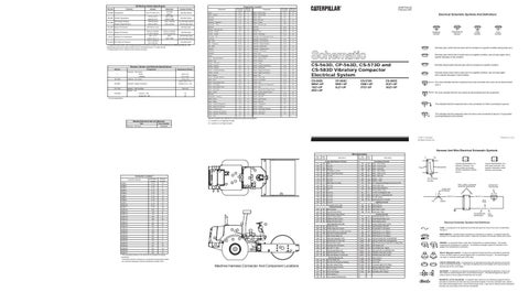
Machine Harness Connector And Component Locations
Typical representation of a Deutsch connector. The plug contains all sockets and the receptacle contains all pins.
2
Typical representation of a Sure-Seal connector. The plugand receptacle contain both pins and sockets.
Pin or Socket Number Wire, Cable, or Harness Assembly Identification
Component Part Number
Single Wire Connector C
A
A 325-PK-14
Pin
AA 1
9X-1123 325-PK-14
Wire Color
Socket
2
200-BK-14
Circuit Number Identification
Control Circuits
301
1 2
1 2
Receptacle
Plug
Lighting Circuits
200
AA 1
Accessory Circuits
101
17
A
Description
Wire Gauge
Electrical Schematic Symbols And Definitions FUSE - A component in an electrical circuit that will open the circuit if too much current flows through it. REED SWITCH - A switch whose contacts are controlled by a magnet. A magnet closes the contacts of a normally open reed switch; it opens the contacts of a normally closed reed switch.
T
SENDER - A component that is used with a temperature or pressure gauge. The sender measures the temperature or pressure. Its resistance changes to give an indication to the gauge of the temperature or pressure. RELAY (Magnetic Switch) - A relay is an electrical component that is activated by electricity. It has a coil that makes an electromagnet when current flows through it. The electromagnet can open or close the switch part of the relay. CIRCUIT BREAKER (C/B) - A component in an electrical circuit that will open the circuit if too much current flows through it. This does not destroy the circuit breaker and it can be reset to become part of the circuit again. SOLENOID - A solenoid is an electrical component that is activated by electricity. It has a coil that makes an electromagnet when current flows through it. The electromagnet can open or close a valve or move a piece of metal that can do work. MAGNETIC LATCH SOLENOID - A magnetic latch solenoid is an electrical component that is activated by electricity and held latch by a permanent magnet. It has two coils (latch and unlatch) that make electromagnet when current flows through them. It also has an internal switch that places the latch coil circuit open at the time the coil latches.