KENR1885 September 1993
C OMPON ENT LO CA T ION CH A R T M ach in e L oc ati o n
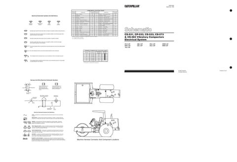
Electrical Schematic Symbols And Definitions
T
Temperature Symbol
Pressure Symbol
Flow Symbol
Level Symbol
Normally open switch that will close with an increase of a specific condition (temp-press-etc.). Normally open switch that is closed due to an applied condition, and will open again with a specific decrease in that condition.
C om pon e nt
S ch em ati c L ocat io n
M ach i ne L o catio n
S ch em ati c L o catio n
Co m p on e nt
1
Alar m — Bac ku p
E-8
11
S ens or — Dru m Speed Pick up
2
Alte r nat or
C- 8
12
S ol enoi d — B rak e
B -5 B -5
3
Bat t er i es
D7, D 8
13
S ol enoi d — E ng ine S hut down
C-8
B
Br ea ker — Alt er nat or
F -4
14
S ol enoi d — E ther S tart Aid
B -8
A
F use Bl ock
F -3
15
Solenoid — Transmission Speed Select
B -5
A
Ga uge — E ngine O il P r es sur e
E-2
16
S ol enoi d — V ibration Con trol
A -6
A
Ga uge — E ngine W at er T em per atur e
F -2
17
S ol enoi ds — P ropel Int erlock
A -5
A
Ga uge — F uel Lev el
E-2
18
S wi tch — Bac kup Al arm
D-2
A
Ga uge — H y dr a uli c T em pe r atu re
E-2
7
Switch — Coolant Temperature (Start Aid)
B -8
A
Ga uge — V ibr a ti on T achom eter
E-2
8
4
H orn — Fo r war d
D- 1
B
S wi tch — Engine O il P re ssure (S ervice M ete r) S wi tch — Fl ood Lamp
A
M et er — Ser v ic e
F -2
B
S wi tch — F orward Horn
D-1
5
M ot or — St ar te r
D- 8
A
S wi tch — Key S tart
E -4
6
R ela y — M ain
F -4
19
S wi tch — Neu tral S tart
B -8
6
R ela y — St ar t
F -4
B
S wi tch — Park B rak e
D-3
7
Sender — Engine Coolant Temperature
C- 7
B
S wi tch — St art A id
F -4
8
Sen de r — Fuel Lev el
C- 7
B
S wi tch — Tra nsm is sio n Spe ed Selec t
D-3
9
Sen de r — Engi ne O il P r essur e
C- 7
B
S wi tch — Vibration O n/Of f
D-2
10
Sen de r — Hy dr aul ic Oil T em perat ur e
C- 7
B
S wi tch — Vi brat ion Sel ec t
D-3
D-7 D-2
CS-531, CP-533, CS-533, CS-573 & CS-583 Vibratory Compactors Electrical System
M ac hin e lo cat i ons ar e r epe at ed f or com ponents loc ated cl ose together.
Normally closed switch that will open with an increase of a specific condition.
A = Loc at ed ins id e in t he das h. B = Loc ate d on th e r ight c ons ole.
Normally closed switch that is open due to an applied condition, and will close again with a specific decrease in that condition.
8YJ1-UP 8PK1-UP 1EL1-UP
The circle indicates that the component has screw terminals and a wire can be disconnected from it.
3BL1-UP 3ZL1-UP
4HL1-UP 5AL1-UP
3WM1-UP 4KM1-UP
H A RN ESS C ON NEC T OR LOC A TIO N C HA R T
No circle indicates that the wire cannot be disconnected from the component.
This indicates that the component has a wire connected to it that is connected to ground.
This indicates that the component does not have a wire connected to ground. It is grounded by being fastened to the machine.
S chemati c Lo cat ion
M achi ne Lo cat ion
P 1 - R1
E -6
1
P 2 - R2
D-6
1
10
P 3 - R3
C-5
2
10
P 4 - R4
D-5
2
10
P 5 - R5
D-5
3
10
P 6 - R6
E -5
3
4
P 7 - R7
A -6
*
Con tac ts
Con nect or
10 10
M ach ine locations ar e r e peat ed for c onnecto rs loc ated c los e t oget her.
* = Connecto r
is locat ed at t he com pon ent.
© 1993 Caterpillar All Rights Reserved
Harness And Wire Electrical Schematic Symbols A
AA
Typical representation of a Deutsch connector. The plug contains all sockets and the receptacle contains all pins.
Receptacle
Plug
1 2
1 2
1
2
Typical representation of a Sure-Seal connector. The plugand receptacle contain both pins and sockets.
11
B 12 18 2 15
16
1
13
Pin or Socket Number
3
A
17
4
Wire, Cable, or Harness Assembly Identification
19 10
Component Part Number
A
A 325-PK-14
Pin
AA 1
1
7
6 9
5
Single Wire Connector C
8
3
2
14
9X-1123 325-PK-14
Wire Color
Socket
2
200-BK-14
Circuit Number Identification
Wire Gauge
Electrical Schematic Symbols And Definitions FUSE - A component in an electrical circuit that will open the circuit if too much current flows through it. REED SWITCH - A switch whose contacts are controlled by a magnet. A magnet closes the contacts of a normally open reed switch; it opens the contacts of a normally closed reed switch.
T
SENDER - A component that is used with a temperature or pressure gauge. The sender measures the temperature or pressure. Its resistance changes to give an indication to the gauge of the temperature or pressure.
A
3
B
14
1 18
RELAY (Magnetic Switch) - A relay is an electrical component that is activated by electricity. It has a coil that makes an electromagnet when current flows through it. The electromagnet can open or close the switch part of the relay.
13
10
4 11
15
2
17
12 6
9
8
2
7
16 19
5 1 3
CIRCUIT BREAKER (C/B) - A component in an electrical circuit that will open the circuit if too much current flows through it. This does not destroy the circuit breaker and it can be reset to become part of the circuit again. SOLENOID - A solenoid is an electrical component that is activated by electricity. It has a coil that makes an electromagnet when current flows through it. The electromagnet can open or close a valve or move a piece of metal that can do work. MAGNETIC LATCH SOLENOID - A magnetic latch solenoid is an electrical component that is activated by electricity and held latch by a permanent magnet. It has two coils (latch and unlatch) that make electromagnet when current flows through them. It also has an internal switch that places the latch coil circuit open at the time the coil latches.
Machine Harness Connector And Component Locations
Printed in U.S.A.