KENR3589 December 2001 Part No.
Off Machine Switch Specification
Function
Actuate
Deactuate
Contact Position
1400 kPa MAX 1100 ± 150 kPa A-B Normally Open (205 psi MAX) (160 ± 22 psi) A-C Normally Closed 60 kPa 28 ± 15 kPa 103-4977 Engine Oil Pressure Normally Open (8.7 psi) (4.0 ± 2.2 psi) 93.0 ± 21.0 kPa 70.0 ± 21.0 kPa 107-0611 Engine Oil Pressure Normally Open (13.5 ± 3.0 psi) (10.2 ± 3.0 psi) Coolant Temperature 107.0 ± 1.5 °C 100 °C MIN A-B Normally Open 108-3190 Hydraulic Oil Temperature (224.6 ± 34.7 °F) (212 °F MIN) B-C Normally Closed 275 to 1750 kPa¹ 114-5333 A/C High/Low Pressure Normally Open² (40 TO 255 psi) ¹ A hysteresis band exists: with increasing pressure the closed condition can be maintained up to 2800 kpa (405 psi), with decreasing pressure the closed condition can be maintained down to 170 kpa (25psi). 3E-7382
VIB Charge Pressure
Schematic Location
² Contact position at the contacts of the harness connector.
Air Conditioner/Heater
F-10
Resistor - Neutral Start Switch
C-10
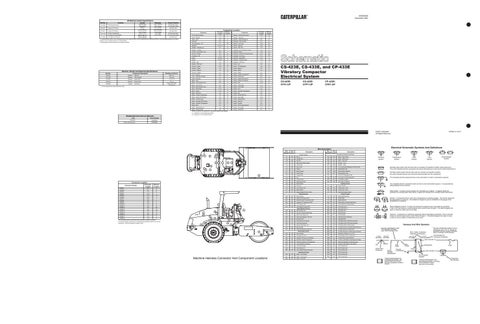
Machine Location 18
Alarm - Backup
D-12
2
Resistor - Start Aid
C-9
18
Alarm - Horn
C-3
3
Resistor - VIB Controller (2)
E-7
B
Alternator
D-11
4
Rheostat - VIB Controller
E-7
B
Arc Suppressor - A/C
H-7
25
Sender - Fuel Level
D-12
20
D-11,D-12
5
Sensor - Start Aid
D-10
28
Breaker - Alternator (2)
D-11
13
Sensor - VIB Tach
C-8
14
Breaker - Throttle
B-7
13
Solenoid - A/C Compressor Group
H-6
25
Control - CAT Product Link
B-8
7
Solenoid - Brake
D-9
23
Control - Throttle
D-4
B
Solenoid - Cold Start Timing Advance
C-12
25
Controller - VIB
D-3
B
Solenoid - Fuel Pump
C-11
25
Diode
F-4,G-4
A
Solenoid - Speed Shift
D-9
17
Fuses
D-5,D-6
B
Solenoid - Throttle Control
C-10
18
Gauge - Fuel
H-3
A
Solenoid - VIB Pump
C-9
15
Gauge - VPM Tach
G-3
A
Switch - A/C
H-8
B
Ground - Engine
D-10
26
Switch - A/C Refrigerant
H-6
25
Ground - Frame
C-9
7
Switch - Beacon
E-7
B
Ground - Platform
C-4
27
Switch - Brake
D-4
B
Ground - Platform
F-9
27
Switch - Brake
D-7
B
Horn - Forward
F-5
6
Switch - Coolant Temperature
D-11
4
Lamp - Alternator Indicator
F-3
A
Switch - Disconnect
D-11
13
Lamp - Warning
F-3
A
Switch - Engine Oil Pressure
C-11
10
Meter - Hour
H-3
A
Switch - Engine Oil Pressure
C-11
10
Motor - Front Washer Fluid
G-8
11
Switch - Fan
H-10
B
Batteries
Part No.
Resistor, Sender and Solenoid Specifications Component Description
7W-1251
Resistance (Ohms)¹
Resistor:
Start Aid
0.85 ± 0.1
137-1761
Resistor:
VIB Controller
147-6937
Solenoid:
Speed Shift
41.74 ± 4.2
148-1517
Resistor:
Neutral Start
10 ± .3
153-4981
Sender:
130 ± 6.5
Empty: 240 to 250 Full: 28 to 33
Fuel Level
¹ At room temperature unless otherwise noted.
Component Location Machine Location 1
Component
Component
Schematic Location
Motor - Front Wiper
E-9
8
Switch - Flood Light
E-7
B
Motor - Rear Washer Fluid
G-8
11
Switch - Front Wiper
H-10
B
Motor - Rear Wiper
E-10
9
Switch - Horn
G-4
A
Motor - Starter
D-10
12
Switch - Hydraulic Temperature
C-9
16
Relay - Brake (2)
C-6
B
Switch - Key
E-3
A
Relay - Coolant Temperature
C-6
B
Switch - Neutral Start (2)
Relay - Engine Oil Pressure
C-6
B
Switch - Rear Wiper
Relay - Function Light
B-6
B
Relay - Hydraulic Oil Pressure
C-6
Relay - Hydraulic Temperature
D-9
23
G-10
B
Switch - Speed Select
H-4
A
B
Switch - Start Aid
E-4
A
B-5
B
Switch - Throttle
H-4
A
Relay - Main
B-3
11
Switch - VIB Charge Pressure
D-10
19
Relay - Neutral Start (2)
C-5
B
Switch - VIB On/Off
D-4
B
Relay - Warning Light
C-5
B
Switch - VIB Select
E-7
B
CS-423E, CS-433E, and CP-433E Vibratory Compactor Electrical System CS-423E: CFX1-UP
CS-433E: CFP1-UP
CP-433E: CFK1-UP
Machine locations are repeated for components located close together. A = Located in or on the Steering Console. B = Located in or on the Right Console.
Related Electrical Service Manuals Title
Form Number
Alternator:
SENR3685
Electric Starting Motor:
SENR3828
Printed in U.S.A.
© 2001 Caterpillar All Rights Reserved
13
5
4
17
28
26
6 9
23
1
15
A
24
8
18 2
25
20
10
16
21
3
B
16
7
27
11
14
Connector Location
Wire Color
101
RD
103
Electrical Schematic Symbols And Definitions
Wire Number
Wire Color
Bat (+)
503
BR
Wiper - Rear (Park)
YL
Throttle SW
504
YL
Wiper - Rear (Low)
105
BR
Key SW
505
BU
Wiper - Rear (HI)
112
PU
Main Power Relay Output
506
PU
Washer - Front
115
PK
Front Flood
507
WH
Washer - Rear
116
BR
Rear Flood
513
OR
A/C Compressor/Refrigerant Pressure SW
118
GY
Wipers
515
GY
Blower Motor (HI)
121
YL
Backup Alarm
516
GN
Blower Motor (Medium)
122
RD
Dome Lamp
517
BU
Blower Motor (Low)
123
WH
Gauge Relay
521
YL
A/C SW To Refrigerant SW
124
GN
A/C
522
WH
A/C Clutch To Thermostat SW
128
RD
Forward Horn
567
WH
A/C Switch Jumper
143
PK
Speed Select SW
568
GN
Horn Alarm to Diodes
143
BR
Brake Switch
148
WH
Start Aid
603
PU
Rotary Beacon
Description Power Circuits
12
19
Wire Number
Wire Description
Description Accessory Circuits (Continued)
Machine Location
CONN 1
D-12
19
170
RD
CAT Product Link
607
PK
Flood Lamp - Front
CONN 2
G-11
21
177
RD
Main Breaker
608
GN
Flood Lamp - Rear
CONN 3
F-11
21
181
GY
Engine Speed Control (+) Bat
615
YL
Cab Flood Lamps (Rops)
CONN 4
A-10
7
CONN 5
C-9
15
CONN 6
A-9
7
Ground Circuits BK
Main Chassis
751
GN
Speed Shift Solenoid
220
BK
Engine Oil Pressure SW
776
YL
Brake Relay
777
PU
Brake Solenoid
CONN 7
B-8
7
CONN 8
C-8
11
221
BK
Engine Coolant Temperature SW
CONN 9
C-8
11
226
BK
Hydraulic Oil Temperature SW
C720
BU
Brake Relay to Neutral Start Relay
CONN 10
E-8
21
CONN 11
H-8
B
229
BK
CAT Product Link
F765
BR
Park Brake SW to Brake Relay
CONN 12
E-5
24
276
BK
VIB Charge Pressure SW
892
BR
CAT Data Link (-)
CONN 13
E-5
24
Basic Machine Circuits
893
GN
CAT Data Link (+)
CONN 14
E-5
24
CONN 15
D-4
B
4
CONN 16
D-4
B
25
CONN 17
C-3
3
9 A 8 28
18
CONN 18 C-3 B The connectors shown in this chart are for harness to harness connectors. Connectors that join a harness to a component are generally located at or near the component. See the Component Location Chart.
26 16
2 5
13
10
12
B
19
21
1
3 27
11
17 7
24
6
23 15
20 16
306
GN
Starter Relay Coil
C801
PU
VIB Select SW
307
OR
Key SW to Neutral Start Relay
E825
GN
VIB Controller
308
YL
Main Power Relay Coil
906
PU
VIB Controller
309
GY
Alternator Regulator Terminal
916
BU
VIB Controller to Rheostat
321
BR
Backup Alarm
919
GN
VIB Select SW
322
GY
Warning Horn (Forward)
920
GN
VIB Select SW to VIB Pump Solenoid
326
PU
Fuel Pump Solenoid
921
WH
VIB Select SW to VIB Pump Solenoid
330
YL
Neutral Start Relay Coil
924
GN
VIB Select SW to VIB Controller
373
GN
Start Aid SW
A919
BU
Throttle Control to Throttle Control Solenoid
377
OR
Start Aid Resistor to Start Aid
A982
BR
Throttle Control to Throttle SW
A983
BU
Throttle Control to Throttle Control Solenoid
400
GN
Service Meter
C901
PU
Rheostat to Resistor ( Loc. E-7)
403
GN
Alternator (R) Term.
C905
OR
Speed Select SW to Throttle SW
405
GY
Opr Mon Oil Press. (Low Setting)
C906
PU
Throttle SW to VIB On/Off SW
406
PU
Opr Mon Coolant Temperature
C930
BR
Function Light Relay to Warning Light Relay
428
OR
Opr Mon Hydraulic Oil Temperature
C931
OR
Warning Light Relay to Warning Light
439
YL
Lamp (Alternator Indicator)
C938
BR
Function Light Relay to Horn Alarm
447
PK
Fuel Level Gauge
T930
WH
CAT Product Link
450
YL
Tach Sender (+)
T931
YL
CAT Product Link
465
OR
Low Charge Pressure Warning
T932
PK
CAT Product Link
T934
OR
CAT Product Link
Monitoring Circuits
14
Accessory Circuits
Machine Harness Connector And Component Locations
Normally open switch that will close with an increase of a specific condition (temp-press-etc.). The circle indicates that the component has screw terminals and a wire can be disconnected from it. Normally closed switch that will open with an increase of a specific condition. No circle indicates that the wire cannot be disconnected from the component. This indicates that the component has a wire connected to it that is connected to ground.
This indicates that the component does not have a wire connected to ground. It is grounded by being fastened to the machine. Reed Switch - A switch whose contacts are controlled by a magnet. A magnet closes the contacts of a normally open reed switch; it opens the contacts of a normally closed reed switch.
Control Circuits
200
500
BR
Wiper - Front (Park)
T935
BU
CAT Product Link
501
GN
Wiper - Front (Low)
T936
GN
CAT Product Link
502
OR
Wiper - Front (HI)
Circuit Breaker Symbol
Flow Symbol
Level Symbol
Temperature Symbol
Lighting Circuits
Schematic Location
Connector Number
T
Pressure Symbol
Sender - A component that is used with a temperature or pressure gauge. The sender measures the temperature or pressure. Its resistance changes to give an indication to the gauge of the temperature or pressure.
T
Relay (Magnetic Switch) - A relay is an electrical component that is activated by electricity. It has a coil that makes an electromagnet when current flows through it. The electromagnet can open or close the switch part of the relay. Solenoid - A solenoid is an electrical component that is activated by electricity. It has a coil that makes an electromagnet when current flows through it. The electromagnet can open or close a valve or move a piece of metal that can do work.
Harness And Wire Symbols Harness identification code This example indicates wire 135 in harness "AG". * * AG-C3 C-C4 130-6795 130-6795 325-A135 PK-14 Socket
Pin
Single Wire Connector
1 2
Wire Color
Ground Circuit Connection Number Identification Typical representation of a Deutsch connector. The plug contains all sockets and the receptacle contains all pins.
* Harness identification letter(s) and a serializing code. The "C" stands for connector and the number indicates which connector in the harness.
Wire, Cable, or Harness Assembly Identification Part Number For L-C12* AG-C4* Connector Assembly 3E-5179 111-7898 325-A135 PK-14 1 Wire Gauge
Receptacle Plug
2
200-L32 BK-14 Pin or Socket Number
1 2
Fuse
Typical representation of a Sure-Seal connector. The plug and receptacle contain both pins and sockets.
105-9344 Component Part Number