KENR1689 April 1993
11
COMPONENT LOCATION CHART 18
12 15
3
Machine Location
2
A 6
8
13
19 10
17
4
16
1
B
3
7
9
1
2
5 14
Schematic Location
Component
Machine Location
Schematic Location
Component
1
Alarm — Backup
E-8
11
Sensor — Compactor Drum Speed
2
Alternator
C-8
12
Solenoid — Brake
B-5
3
Battery
D-7
13
Solenoid — Engine Shutdown
C-8
3
Battery
D-8
14
Solenoid — Ether Start Aid
B-8
B
Breaker — Alternator
F-4
15
Solenoid — Trans Speed Select
B-5 A-6
B-5
A
Fuse Block
E-3, F-3
16
Solenoid — Vibration Control
A
Gauge — Engine Oil Pressure
E-2
17
Solenoids — Propel Interlock
A-5
A
Gauge — Engine Water Temp
E-2
18
Switch — Backup Alarm
D-2
A
Gauge — Fuel Level
E-2
7
Switch — Coolant Temp (Start Aid)
B-8
A
Gauge — Hydraulic Temperature
E-2
8
Switch — Engine Oil Pressure
C-7
A
Gauge — Vibration Tachometer
D-2
B
Switch — Ether Start Aid
E-4
4
Horn — Forward
D-1
B
Switch — Flood Lamp
C-2
A
Meter — Service
E-2
B
Switch — Forward Horn
C-1
5
Motor — Starter
D-8
A
Switch — Key Start
E-4
6
Relay — Main
F-4
19
Switch — Neutral Start
B-8
6
Relay — Start
E-5
B
Switch — Park Brake
D-3
7
Sender — Engine Coolant Temp
C-7
B
Switch — Transmission Speed Select
C-3
8
Sender — Engine Oil Pressure
C-7
B
Switch — Vibration On/Off
D-2
9
Sender — Fuel Level
B-7
B
Switch — Vibration Select
C-3
10
Sender — Hydraulic Oil Temp
C-7
Machine locations are repeated for components located close together. A = Located inside in the dash. B = Located on the right console.
3
CS-563
A B
10 2
18 15 12
6
8
7
2
5
9
1 3
11
8XF779-UP 7GG400-UP
1YJ385-UP 5AJ106-UP
HARNESS CONNECTOR LOCATION CHART
16
19
17
13
14
1
4
CAT
CP-563 & CS-563 Vibratory Compactors Electrical System
Schematic Location
Machine Location
P1 - R1
E-6
1
P2 - R2
D-6
1
10
P3 - R3
C-5
2
10
P4 - R4
D-5
2
10
P5 - R5
D-5
3
10
P6 - R6
E-5
3
4
P7 - R7
A-6
*
Contacts
Connector
10 10
Machine locations are repeated for connectors located close together. * = Connector is located at the component.
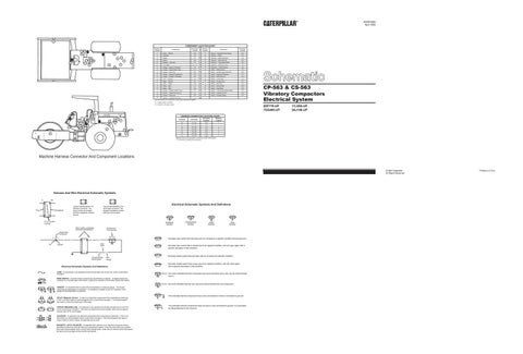
Machine Harness Connector And Component Locations
© 1993 Caterpillar All Rights Reserved
Harness And Wire Electrical Schematic Symbols A
AA
Typical representation of a Deutsch connector. The plug contains all sockets and the receptacle contains all pins.
Receptacle
Plug
1 2
1 2
1
2
Typical representation of a Sure-Seal connector. The plugand receptacle contain both pins and sockets.
T
Pin or Socket Number
Pressure Symbol Wire, Cable, or Harness Assembly Identification
A
A 325-PK-14
Pin
AA 1
9X-1123 325-PK-14
Wire Color
Socket
2
Temperature Symbol
Level Symbol
Flow Symbol
Component Part Number
Single Wire Connector C
Electrical Schematic Symbols And Definitions
Normally open switch that will close with an increase of a specific condition (temp-press-etc.). Normally open switch that is closed due to an applied condition, and will open again with a specific decrease in that condition.
200-BK-14
Circuit Number Identification
Wire Gauge
Electrical Schematic Symbols And Definitions FUSE - A component in an electrical circuit that will open the circuit if too much current flows through it. REED SWITCH - A switch whose contacts are controlled by a magnet. A magnet closes the contacts of a normally open reed switch; it opens the contacts of a normally closed reed switch.
Normally closed switch that will open with an increase of a specific condition.
Normally closed switch that is open due to an applied condition, and will close again with a specific decrease in that condition.
The circle indicates that the component has screw terminals and a wire can be disconnected from it.
No circle indicates that the wire cannot be disconnected from the component.
T
SENDER - A component that is used with a temperature or pressure gauge. The sender measures the temperature or pressure. Its resistance changes to give an indication to the gauge of the temperature or pressure. RELAY (Magnetic Switch) - A relay is an electrical component that is activated by electricity. It has a coil that makes an electromagnet when current flows through it. The electromagnet can open or close the switch part of the relay. CIRCUIT BREAKER (C/B) - A component in an electrical circuit that will open the circuit if too much current flows through it. This does not destroy the circuit breaker and it can be reset to become part of the circuit again. SOLENOID - A solenoid is an electrical component that is activated by electricity. It has a coil that makes an electromagnet when current flows through it. The electromagnet can open or close a valve or move a piece of metal that can do work. MAGNETIC LATCH SOLENOID - A magnetic latch solenoid is an electrical component that is activated by electricity and held latch by a permanent magnet. It has two coils (latch and unlatch) that make electromagnet when current flows through them. It also has an internal switch that places the latch coil circuit open at the time the coil latches.
This indicates that the component has a wire connected to it that is connected to ground.
This indicates that the component does not have a wire connected to ground. It is grounded by being fastened to the machine.
Printed in U.S.A.