3 minute read
towing and free wheeling—single torque hub (2-wd) type 5


d. Turn Blockside: Turning can be achieved in two different ways. One of which is by operating the crawler tracks in opposite directions, which causes the BTP to make a quick and highly maneuverable spin about the center of the crawler tracks. The second way is to move only one crawler track and allow the other to drag on the ground. This will provide a turn at a slightly higher radius with an increase of stress and wear on the cat pads. To spin the BTP operate the right crawler control flipper or lever labeled “Crawler Inbye Blockside”, under the section labeled “Tram”, in the “REV” (reverse) direction while simultaneously operating the left crawler control flipper or lever labeled “Crawler
Outbye Walkside”, under the section labeled
“Tram”, in the “FWD” (forward) direction. To use the second option of dragging the opposing track, just operate one of the crawler control flippers or levers mentioned above.
3. Once the BTP is positioned in a desired location, finish up by following the last steps of the standard BTP start-up procedure (see the “Start-up Procedure” section).
TOWING AND FREE WHEELING – SINGLE TORQUE HUB (2WD) TYPE
The following procedure should be followed during towing and freewheeling:
1. Retract all stab shoes, anchoring cylinders, side-slew jacks so that only the crawlers are in contact with the ground. 2. Should the BTP employ a restraining or anchoring device to resist the belt tension, this device must be released so that the unit can be moved. If DBT America provided the restraining device then refer to the section in this manual on “Releasing the Restraining
Device” for proper operation or follow the guidelines specified by the mine. The complete restraining device should be completely disconnected. 3. Raise the BTP up as high as possible using only the crawler lift jacks (see the “Crawler Lift Jacks” section). Then place crib blocks or heavy-duty steel stands under the frame so that it is physically held in place as to avoid unexpected cylinder drift or collapse. 4. Shut down the hydraulic power to the BTP (follow the “Shut Down
Procedure”). 5. The free wheeling mechanism can be accessed in one of two ways either by crawling under the belt tailpiece or reaching your hands between the tailpiece and crawler frames.
WARNING Do not try to access the free wheeling mechanism while the BTP is powered or without some form of mechanical stops holding up the BTP frame or else death or serious injury may result.
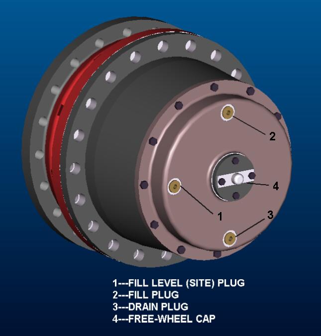
6. The backside of the torque hub has a cap, which is bolted on with two hex head bolts. Remove the two bolts and then remove the cap. The cap will have a knob that protrudes from its center. Take the cap and reverse its position so that the knob faces the torque hub and replace both bolts. As the bolts are tightened, the knob pushes out the center pin which pushes the sun gear out of engagement with the other planet gears thus allows the torque hub to free wheel. Repeat this step for both crawlers.
7. Remove the crib blocks or supports from under the BTP frame.
Disconnect the main pressure and return line from the mine’s hydraulic power system (see the “Pressure and Return Line
Connection Station” section). Ensure that the main hydraulic lines are not pressurized. Follow the standard procedure set by the mine for setup and connection of equipment within the mine. 8. The BTP is now ready to be towed or free wheeled. To tow the
BTP attach towing chains or cables to a secure structural member such as the lifting eyes, winch connection points or the towing yoke if provided (see the “Winch Restraining Device” section). Then pull the BTP to a new desired location and repeat steps one through four and finish by reversing the cap in step five and reconnecting the hydraulic power in step six if so desired.
© DBT AUSTRALIA 2007