Component Location Schematic Location E-15
Machine Location 11
B-12
12
Solenoid - Brake
H-14
3
F-10, G-10
B
Solenoid - Cold Start Timing
C-14
13
C-12
5
Solenoid - Drum Offset
H-13
24
Beacon - Light
E-3
18
Solenoid - Flow Divider
E-13
15
Breaker - Light
C-4
B
Solenoid - Fuel Shut-off
C-14
13
A-B Normally Open B-C Normally Closed
Breaker - Throttle Control
D-3
19
Solenoid - Rear Wheel
H-13
1
Cluster - Diagnostic Light
H-7
A
Solenoid - Speed
H-14
3
Normally Closed
Cluster - Functional Light
H-9
A
Solenoid - Throttle Control
D-14
13
Off Machine Switch Specification Part No. 9D-7032
Function Backup Alarm Pressure
103-4977
Hour Meter Pressure
107-0611
Engine Oil Pressure
108-3190
Engine Coolant Temp.
114-4308
Hydraulic Temperature
165-2521
Hydraulic Oil Pressure
Component
Actuate
Deactuate
517 ± 34.5 kPa MAX (75 ± 5 psi MAX) 60 kPa MAX (8.7 psi MAX) 93 ± 21 kPa (13.5 ± 3.1 psi) 107 ± 1.5 °C (224.6 ± 34.7 °F) 92 ± 2.8 °C (198 ± 37 °F) 1400 kPa MAX (205 psi MAX)
414 ± 34.5 kPa MIN (60 ± 5 psi MIN) 28 ± 15 kPa (4 ± 2 psi) 70 ± 21 kPa (10.2 ± 3.1 psi) 100 °C MIN (212 °F MIN) 83 °C MIN (181 °F MIN) 1100 ± 75 kPa (160 ± 11 psi)
Contact Position Normally Open
Alarm - Backup Alternator Assembly - Diode
Normally Open Normally Open
Batteries
Flasher A-C Normally Closed A-B Normally Open
B
Solenoid - Vibration Control
G-15
7
A
Starter Motor
B-12
6
Fuses - Cab Option
H-1
C
Switch - Rear Wheel
C-2
B
Gauge - Fuel
I-9
A
Switch - 3 Speed
F-5
B
Gauge - Ground Speed
I-8
A
Switch - Auto Vibration (Fwd)
G-3
B
Gauge - Vibration Tach
I-9
A
Switch - Auto Vibration (Rev)
G-3
B
Horn - Warning
E-12, E-10
16
Switch - Auto/Manual
H-4
B
Lamp - Indicator
G-9
A
Switch - Backup Alarm Pressure
G-5
B
Lamp - Flow divider indicator
C-2
C
Switch - Beacon
H-1
C
Motor - Front Wiper
6T-3670 140-2238
Resistor: Cold Start Timing
¹ At room temperature.
4
Switch - Brake
G-4
B
22
Switch - Disconnect
C-12
2
F-2
22
Switch - Drum Offset
14
Switch - Engine Coolant Temperature
Motor - Rear Wiper
F-2
25
Switch - Engine Oil Pressure
C-15
9
Empty: 0 to 3 Full: 86 to 94
Motor - Washer
F-1
26
Switch - Fan
H-1
C
Relay - Brake #1
F-4
20
Switch - Flow Divider
E-3
C
25
Relay - Brake #2
F-4
20
Switch - Front Water Spray
B-3
B
Relay - Coolant Temperature
D-5
20
Switch - Front Wiper/Washer
G-1
C
Relay - Engine Oil Pressure
D-5
20
Switch - Hour Meter Pressure
C-15
9
Relay - Functional Light
E-5
20
Switch - Hydraulic Oil Pressure
E-12
9
Relay - Hydraulic Charge Oil Pressure
D-5
20
Switch - Hydraulic Temperature
E-12
4
Relay - Hydraulic Temperature
E-5
20
Switch - Ignition
G-9
A
B-2
20
Switch - Interior Light
I-1
23
B-11, C-3
B
Switch - Light
C-4
B B
Resistance (Ohms)¹
Sender: Fuel Level
I-7 D-12 D-14
Motor - Rear Water Pump
Resistor, Sender and Solenoid Specifications
Relay - Intermittent Relay - Main
C-1
B
D-15, C-14
10
Relay - Neutral Start # 1
I-4
20
Switch - Neutral Start
G-4
Relay - Neutral Start # 2
F-4
20
Switch - Rear Water Spray
C-3
B
B-12
20
Switch - Rear Wiper/Washer
F-2
C
Relay - Warning Light
E-5
20
Switch - Start Aid
Resistor - Cold Start Timing
C-14
B
Switch - Throttle Control
Resistor - Fuel Shut-off
C-14
B
Resistor - Start Aid
E-5
B
Sender - Fuel
E-12
8
Sensor - Front Speed
E-14
21
Relay - Start
KENR2756 January 2000
Machine Location 21
B-4
Motor - Front Water Pump
Component Description
Sensor - Front Vibration Sensor
Schematic Location E-12
G-8, G-7
Fuses
Meter - Hour
Part No.
Component
G-9
A
H-7, D-3
A
Switch - Turn Light
B-5
B
Switch - Vibration On/Off
G-4
B
Switch - Warning Horn
G-5
B
Electrical Schematic Symbols And Definitions
T
Temperature Symbol
Pressure Symbol
Flow Symbol
Level Symbol
Normally open switch that will close with an increase of a specific condition (temp-press-etc.).
Normally open switch that is closed due to an applied condition, and will open again with a specific decrease in that condition.
CB-535B Vibratory Compactor Electrical System
Normally closed switch that will open with an increase of a specific condition.
Normally closed switch that is open due to an applied condition, and will close again with a specific decrease in that condition.
3AR152-UP The circle indicates that the component has screw terminals and a wire can be disconnected from it.
No circle indicates that the wire cannot be disconnected from the component.
Machine locations are repeated for components located close together. A Located in or near the center dash panel. B Located in or near the lefthand dash panel. C Located in or near the righthand dash panel.
Related Electrical Service Manuals Title
This indicates that the component has a wire connected to it that is connected to ground.
Form Number
Alternator:
9W-3043
SENR3685
Electric Starting Motor:
143-0541
SENR3828
This indicates that the component does not have a wire connected to ground. It is grounded by being fastened to the machine.
Printed in U.S.A.
© 2000 Caterpillar All Rights Reserved
Harness And Wire Electrical Schematic Symbols Wire Description Wire Number
Wire Color
Description
Wire Number
Wire Color
Power Circuits
29
28
15 25
Connector Location
27
Description
101
RD
Bat (+)
B439
RD
Front Drum Vpm Sensor
103
YL
Aux Ckt
B440
GN
Rear Drum Vpm Sensor
105
BR
Key Sw
B440
RD
Vibration Sensor
109
OR
Alt Output (+) Term.
B440
WH
Vibration Sensor
110
GN
Water Spray Fuse
112
PU
Main Power Rly Output
537
GN
Turn Signal SW To Flasher
114
GN
Light Switch
568
GN
Warning Buzzer To Diodes
121
YL
Back Alarm To Lamp
123
WH
Gauges
604
OR
Stop Lamp
148
WH
Start Aid
605
YL
Turn Lamp - Left
155
PK
Brake Fuse
606
GY
Turn Lamp - Right
173
YL
Flasher (option)
608
GN
Flood Lamp - Rear
175
PK
Drum Offset
611
PU
Head Lamp Hi
176
WH
Recording Module (option)
614
PU
Park/Tail/Dash/Lamp
E-15
26
176
YL
Recording Module (option)
619
GN
Head Lamp Lo
CONN 2
E-14
27
181
GY
Eng Speed Ctrl (+) Bat
635
BR
Flasher to Indicator
CONN 3
Ground Circuits
27
CONN 4
F-13
27
200
BK
Main Chassis
751
GN
XMSN Shift Sol No1 Or 3
CONN 5
C-11
32
200
GY
Main Chassis
777
PU
Brake Release Motor
CONN 6
E-11
32
206
BK
Bat Side Of Disconnect
B765
BR
Park Brake SW To Relay
CONN 7
E-11
27
220
BK
Eng Oil Press Sensor
C720
BU
Relay Interlock
CONN 8
B-10, I-2
12
221
BK
Eng Coolant Temp Sensor
C729
BU
Rear Wheel - SW To Sol
BK
Hyd Oil Temp Sensor
C730
BR
Flow Divider - SW to Sol
BK
XMSN Ctrl Ident Code 0
C850
GN
Amp Signal To Recording Module
Basic Machine Circuits
C851
PU
Speed Amplifier
CONN 9
B-10, I-2
12
226
CONN 10
B-10, I-2
12
276
CONN 11
F-9
A
CONN 12
F-8
A
304
WH
Starter Relay No1 Output
A919
BU
Left Eng Throttle SW To Relay/Diode
CONN 13
F-8
A
306
GN
Starter Relay Coil To Neut Start SW
A920
BR
Left Eng Throttle SW To Relay/Diode
307
OR
Key SW To Neutral Start SW
A953
PK
Right Console Eng Throttle SW To Relay/Diode
308
YL
Main Power Relay Coil
A982
BR
Eng Throttle Cont
309
GY
Alternator Regulator Term.
A983
BU
Eng Throttle Cont - Signal
CONN 14
F-8
A
CONN 15
F-7
A
CONN 16
H-4
B
CONN 17
D-3, G-2
C
321
BR
Backup Alarm Lamp
B920
GN
FWD/REV (Fwd) SW To EDC
GY
Warning Horn (Forward)
B921
WH
FWD/REV (Rev) SW To EDC
CONN 19
H-2
C
322
CONN 20
H-2, E-1
C
326
PU
Key SW "C" Term.
C922
BR
Front Drum Water Pump
CONN 21
H-2
C
330
YL
Neutral Start Relay Coil
C923
OR
Rear Drum Water Pump
GN
Start Aid SW To Start Aid Resistor
C924
YL
Forward Vibratory Valve
OR
Start Aid Resistor To Start Aid
C925
GN
Reverse Vibratory Valve
C926
BU
Front Drum Select Solenoid
CONN 22
G-2
C
376
CONN 23
G-2
C
377
Monitoring Circuits
CONN 24 G-2 C The connectors shown in this chart are for harness to harness connectors. Connectors that join a harness to a component are generally located at or near the component. See the Component Location Chart. 26 28
14 15 29
27
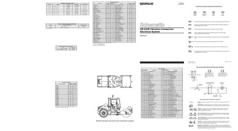
Machine Harness Connector And Component Locations
Pin or Socket Number Wire, Cable, or Harness Assembly Identification
400
GN
Service Meter SW
C928
GY
Left Hand Offset
405
GY
Opr Mon Oil Press(Low Setting)
C929
WH
Right Hand Offset
406
PU
Opr Mon Coolant Temp
C930
BR
Functional Lights GP to Relay
419
YL
Opr Mon Parking Brake
C931
OR
Warning Lights GP to Relay
428
OR
Opr Mon Xmsn Oil Temp
C932
YL
Vib Cut-Out SW to Auto Vib SW
439
YL
Lamp Indicator
C933
GN
Auto/Manual SW to Forward/Reverse Press SW
447
PK
Fuel Level Gauge
C934
BU
Auto Vib SW to Forward/Reverse SW
449
BU
Speed Amplifier
C935
PU
Front SW to Timer
449
RD
Spdom Sender (Signal No. 1)
C936
GY
Spray SW to Front Water Pump
449
WH
Spdom Sender (Signal No. 1)
C937
WH
Intermittent Relay To Timer
450
BU
Vibration Amplifier
C938
BR
Diagnostic Warning Horn
450
YL
Tach Sender (+)
N909
PU
Timing Advance Request
465
OR
Low Charge PressWarning
N910
GN
Timing Advance Command
B438
OR
Water Spray Indicator
Component Part Number
Single Wire Connector C
Control Circuits
D-13
25
2
Typical representation of a Sure-Seal connector. The plugand receptacle contain both pins and sockets.
Lighting Circuits
CONN 1
14
Typical representation of a Deutsch connector. The plug contains all sockets and the receptacle contains all pins.
Receptacle
Plug
1 2
1 2
Accessory Circuits
Machine Location
Connector Number
AA 1
Monitoring Circuits (Continued)
Schematic Location
26
A
A
A 325-PK-14
Pin
AA 1
9X-1123 325-PK-14
Wire Color
Socket
2
200-BK-14
Circuit Number Identification
Wire Gauge
Electrical Schematic Symbols And Definitions FUSE - A component in an electrical circuit that will open the circuit if too much current flows through it. REED SWITCH - A switch whose contacts are controlled by a magnet. A magnet closes the contacts of a normally open reed switch; it opens the contacts of a normally closed reed switch.
T
SENDER - A component that is used with a temperature or pressure gauge. The sender measures the temperature or pressure. Its resistance changes to give an indication to the gauge of the temperature or pressure.
RELAY (Magnetic Switch) - A relay is an electrical component that is activated by electricity. It has a coil that makes an electromagnet when current flows through it. The electromagnet can open or close the switch part of the relay. CIRCUIT BREAKER (C/B) - A component in an electrical circuit that will open the circuit if too much current flows through it. This does not destroy the circuit breaker and it can be reset to become part of the circuit again. SOLENOID - A solenoid is an electrical component that is activated by electricity. It has a coil that makes an electromagnet when current flows through it. The electromagnet can open or close a valve or move a piece of metal that can do work. MAGNETIC LATCH SOLENOID - A magnetic latch solenoid is an electrical component that is activated by electricity and held latch by a permanent magnet. It has two coils (latch and unlatch) that make electromagnet when current flows through them. It also has an internal switch that places the latch coil circuit open at the time the coil latches.