10
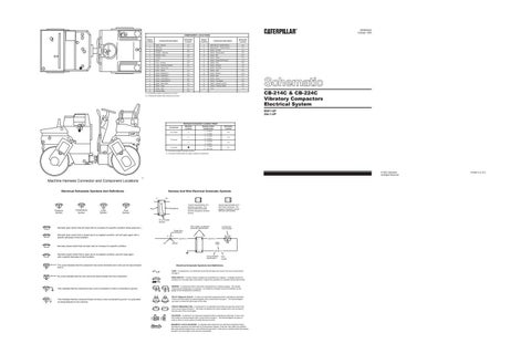
COMPONENT LOCATIONS
B
2
3
Engine Location
6
9 7
11
A
1
5
8 1
4
KENR2533 October 1993
Component Description
Schematic Location
Engine Location
Component Description
Schematic Location
1
Alarm - Backup
C-7
7
Selenoids (2) - Brake/Interlock
2
Alternator
C-3
8
Selenoids (4) - Vibration/Select
E-3 E-3
3
Batteries
B-3
9
Switch - Air Filter
C-3
3
Breaker - Alternator
C-3
B
Switch - Backup Alarm
C-6
3
Breaker - lamp
D-3
10
Switch - Belt
B-3
A
Flasher
D-5
A
Switch - Brake
E-5
3
Fuse
C-2
9
Switch - Engine Oil Pressure
C-3
4
Horn - Forward
E-2
A
Switch - Horn
D-5
A
Lamp - Alternator Indicator
E-5
B
Switch - Interlock
C-6
5
Motor - Spray Pump
C-7
A
Switch - Key Start
C-4
6
Motor - Starter
C-3
A
Switch - Light
E-5
A
Relay - Brake(No.1)
E-4
B
Switch - Neutral
C-6
A
Relay - Brake(No.2)
D-4
11
Switch - Seat
C-7
A
Relay - Interlock(No.1)
D-4
A
Switch - Spray
C-5
A
Relay - Interlock(No.2)
D-4
A
Switch - Turn Signal
D-5
3
Relay - Main Power
D-3
B
Switch - Vibration Control
C-6
A
Relay - Spray
C-4
B
Switch - Vibration Select
C-6
3
Relay - Start
D-3
A
Timer
C-5
A
Service Meter
E-5
CB-214C & CB-224C Vibratory Compactors Electrical System
A = components located in operators front console. B = Components located inside vibratory lever control.
9XK1-UP 3AL1-UP A
Harness Connector Location Chart
11
8
10 9
B
2
Connectors
Machine Location
24 contacts
A
1
CAT
Harness and/or Components A - 1G-4633
1
4
A - 1G-4633 A - 1G-4633
C
C-6
B - 1G4634 A - 1G-4633
1
4 Contacts
C-6
B - 1G4634
6 Contacts
6
D-6
C - 1G-3894
C
3
Schematic Location
B-4
D - 104-7726
A = Connectors located in operator's console.
5
C = Connectors located under floor plate in operator's compartment.
7
© 1993 Caterpillar All Rights Reserved
Machine Harness Connector and Component Locations Electrical Schematic Symbols And Definitions
Harness And Wire Electrical Schematic Symbols A
AA
T
Pressure Symbol
Temperature Symbol
Level Symbol
Flow Symbol
Typical representation of a Deutsch connector. The plug contains all sockets and the receptacle contains all pins.
Receptacle
Plug
1 2
1 2
1
2
Typical representation of a Sure-Seal connector. The plugand receptacle contain both pins and sockets.
Pin or Socket Number Wire, Cable, or Harness Assembly Identification
Normally open switch that will close with an increase of a specific condition (temp-press-etc.).
Component Part Number
Single Wire Connector
Normally open switch that is closed due to an applied condition, and will open again with a specific decrease in that condition.
C
A
A 325-PK-14
Pin
AA 1
Wire Color
Socket
Normally closed switch that will open with an increase of a specific condition. 2
Normally closed switch that is open due to an applied condition, and will close again with a specific decrease in that condition.
9X-1123 325-PK-14
200-BK-14
Circuit Number Identification
The circle indicates that the component has screw terminals and a wire can be disconnected from it.
Wire Gauge
Electrical Schematic Symbols And Definitions FUSE - A component in an electrical circuit that will open the circuit if too much current flows through it.
No circle indicates that the wire cannot be disconnected from the component.
This indicates that the component has a wire connected to it that is connected to ground.
This indicates that the component does not have a wire connected to ground. It is grounded by being fastened to the machine.
REED SWITCH - A switch whose contacts are controlled by a magnet. A magnet closes the contacts of a normally open reed switch; it opens the contacts of a normally closed reed switch.
T
SENDER - A component that is used with a temperature or pressure gauge. The sender measures the temperature or pressure. Its resistance changes to give an indication to the gauge of the temperature or pressure. RELAY (Magnetic Switch) - A relay is an electrical component that is activated by electricity. It has a coil that makes an electromagnet when current flows through it. The electromagnet can open or close the switch part of the relay. CIRCUIT BREAKER (C/B) - A component in an electrical circuit that will open the circuit if too much current flows through it. This does not destroy the circuit breaker and it can be reset to become part of the circuit again. SOLENOID - A solenoid is an electrical component that is activated by electricity. It has a coil that makes an electromagnet when current flows through it. The electromagnet can open or close a valve or move a piece of metal that can do work. MAGNETIC LATCH SOLENOID - A magnetic latch solenoid is an electrical component that is activated by electricity and held latch by a permanent magnet. It has two coils (latch and unlatch) that make electromagnet when current flows through them. It also has an internal switch that places the latch coil circuit open at the time the coil latches.
Printed in U.S.A.