SENR9535 November 1999
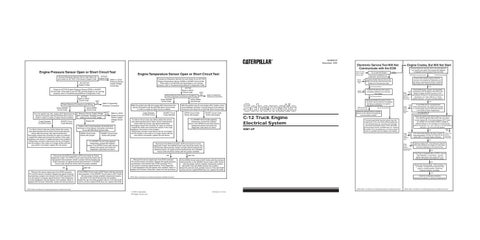
Engine Pressure Sensor Open or Short Circuit Test Connect Electronic Service Tool to Cab Data Link and check for ACTIVE 5 Volt Sensor Supply Code.
ACTIVE Supply Code
NO ACTIVE Supply Codes
Connect an Electronic Service Tool and check for an ACTIVE Engine Temperature Sensor OPEN or SHORT Circuit Code. If the code is not ACTIVE and the Engine is not running properly, refer to Troubleshooting Without A Diagnostic Code. ACTIVE Open or Short Circuit Code
Check for ACTIVE Engine Pressure Sensor OPEN or SHORT Circuit Code. If the code is not ACTIVE and the Engine is not running properly, refer to Troubleshooting Without A Diagnostic Code. ACTIVE Open or Short Circuit Code Check Electrical Connectors and Wiring. Active SHORT Circuit Code Turn the ignition key ON, engine OFF. Disconnect the Sensor Connector with the ACTIVE Short Circuit Code in order to create an Open Circuit condition. Code Changes To OPEN Circuit
SHORT Circuit Code Remains
If a Short Circuit code was Active before the sensor was disconnected and an Open Circuit code became Active after the sensor was disconnected then thoroughly inspect the connector for signs of moisture. Inspect the seals and connect the sensor. If the code reappears, the sensor or pigtail harness is the problem. Temporarily connect a new sensor but do not install it into the engine. If the code is no longer Active with the new sensor connected, replace the old sensor.
Check Electrical Connectors and Wiring. NOT OK
Refer to Inspecting Electrical Connectors
Active OPEN Circuit Code Measure Sensor Supply Voltage with multimeter. Reading should be within 4.5 to 5.5 VDC range. Supply OK
NOT OK Refer to +5Volt Engine Pressure Sensor Supply Voltage Circuit Test
Install a short circuit between terminal-B and terminal-C of the Sensor Connector and check for an ACTIVE Short Circuit code. OPEN Circuit Code Active with jumper
SHORT Circuit Code Active with jumper
OK Remove the sensor signal wire from ECM connector P2 and the sensor connector. Bypass the signal wiring by connecting a jumper wire directly from ECM connector P2 to the sensor connector signal terminal. If the Diagnostic Code disappears with the bypass wire installed, repair or replace the harness. Otherwise, restart the test procedure.
Active SHORT Circuit Code With the ignition key ON and engine OFF, Disconnect the Sensor Connector with the ACTIVE Short Circuit Code in order to create an Open Circuit condition. Code Changes To OPEN Circuit
NOT OK If the OPEN Circuit code is NOT Active with the harness disconnected, or the SHORT Circuit code is NOT Active with the jumper (short) installed, temporarily install a test ECM. If the test ECM resolves the problem, install the old and verify problem returns. If the test ECM works and the original ECM does not, replace the ECM.
SHORT Circuit Code Remains
If a Short Circuit code was Active before the sensor was disconnected and an Open Circuit code became Active after the sensor was disconnected then thoroughly inspect the connector for signs of moisture. Inspect the seals and connect the sensor. If the code reappears, the sensor is the problem. Temporarily connect a new sensor but do not install it into the engine. If the code is no longer Active with the new sensor connected, replace the old sensor.
If a SHORT Circuit Code appears, temporarily connect the suspect sensor. If an OPEN Circuit code returns, replace the sensor and verify the diagnostic code does not return.
Disconnect the ECM Connector J2/P2 and check for Active diagnostic codes. The OPEN Circuit code should be Active with the harness disconnected. Install a jumper (short) between the ECM Connector J2 signal terminal and terminal-3. A SHORT Circuit code should be Active with the jumper installed.
Does not crank, refer to engine will not crank.
Engine Temperature Sensor Open or Short Circuit Test
Refer to +5Volt Pressure Sensor Supply Voltage Circuit Test
NOT OK
Repair Service Tool
OK
Try to start the Engine.
Remove the sensor signal wire from ECM connector P2 and the sensor connector. Bypass the signal wiring by connecting a wire directly from ECM connector P2 to the sensor connector signal terminal. If the Diagnostic Code disappears with the bypass wire installed, repair or replace the harness. Otherwise, restart the test procedure.
Connect Electronic Service Tool to the Cab data link, turn ignition key switch ON, engine OFF. Attempt to establish communications with the ECM.
Does not start
ECM does not communicate
Engine starts, but ECM does not communicate with the Service Tool
Repair Cables
Refer to Inspecting Electrical Connectors
If a SHORT Circuit Code appears, temporarily connect the suspect sensor. If an OPEN Circuit code returns, replace the sensor and verify the diagnostic code does not return.
Connect the Service Tool using a completely different set of Service Tool cables. No Communications
Disconnect ECM Connector P1 from the ECM. Use the Service Tool Bypass Harness as indicated in the Ignition Key Switch Circuit Test.
With the ignition key On and engine OFF, Install a short circuit between terminal-1 and terminal-2 of the Sensor Connector and check for an ACTIVE Short Circuit code. SHORT Circuit Code Active with jumper
OK
ECM and Service Tool Communicate
C-12 Truck Engine Electrical System 9SM1-UP
No Communications
Either the vehicle wiring or another device on the vehicle is causing the communication problem. Connect a test ECM. Turn the Ignition Key ON, engine OFF. If the new ECM communicates and the old ECM does not, reconnect the old ECM and verify the problem returns. If the new ECM communicates and the old ECM does not, replace the ECM. If the new ECM does not communicate, there is a problem with the cables or the battery.
ECM Communicates
Ensure after-market engine protection devices (not installed by Caterpillar) are not active, preventing the ECM or Ignition Key Switch from receiving battery power.
Connect another Service Tool to the ECM, but use the same Service Tool Cables as in the previous step.
OK
NOT OK
Refer to the Ignition Keyswitch Circuit Test
Check ECM power, ground, and keyswitch connections with the ignition key switch ON. Battery voltage at ECM Connector J1/P1 terminal-52, 53 and 70, to terminal-65 and 67 should be 11.0 -13.5 VDC for a 12 Volt system and 22.0 - 27.0 for a 24 Volt system. OK
NOT OK Refer to the ECM Memory Test
A new ECM has an unprogrammed Personality Module. The engine will not start or communicate until the Personality Module in the ECM is Flash Programmed. Not a New ECM
Check the Ignition Key Switch status on the Service Tool. With the Ignition Key Switch ON, the status should display ON. If the status displays OFF, check for voltage from the battery. Battery voltage at ECM Connector J1/P1 terminal-70 to terminal-65 and 67 should be 11.0 -13.5 VDC for a 12 Volt system and 22.0 - 27.0 for a 24 Volt system. NOT OK
OK NOT Refer OK to the ECM Memory Test NOT Refer OK to the Engine Speed/Timing Circuit Test
Disconnect the ECM Connector J2/P2 and check for Active diagnostic codes. The OPEN Circuit code should be Active with the harness disconnected. Install a jumper (short) between the ECM Connector J2 signal terminal and terminal-18. A SHORT Circuit code should be Active with the jumper installed. OK
Engine Cranks, But Will Not Start
No Communications
Active OPEN Circuit Code
OPEN Circuit Code Active with jumper
Electronic Service Tool Will Not Communicate with the ECM
If the Personality Module has been recently replaced/updated , connect and check for an active 252-11 Incorrect Engine Software.
Refer to the Ignition Keyswitch Circuit Test
OK
Observe engine rpm from Electronic Service Tool while cranking the engine. An rpm value should be displayed on the Service Tool. OK
If the Truck is equipped with a CAT ID , ensure Theft Deterrent is not Active . Turn the Ignition Key Switch ON, engine OFF, the CAT ID will indicate Theft Deterrent Active.
NOT OK If the OPEN Circuit code is NOT Active with the harness disconnected, or the SHORT Circuit code is NOT Active with the jumper (short) installed, temporarily install a test ECM. If the test ECM resolves the problem, install the old and verify problem returns. If the test ECM works and the original ECM does not, replace the ECM.
OK
Monitor the exhaust stack while cranking - if no smoke is present there may be a fuel supply or quality problem. Check fuel pressure, priming, and filters. OK
Check for combustion problems, mechanical problems or extreme temperatures.
NOTE: Refer to the Electronic Troubleshooting Guide for detailed information.
NOTE: Refer to the Electronic Troubleshooting Guide for detailed information.
NOTE: Refer to the Electronic Troubleshooting Guide for detailed information.
©1999 Caterpillar All Rights Reserved
Printed in U.S.A.
NOTE: Refer to the Electronic Troubleshooting Guide for detailed information.