123 minute read
Traveling – Restricted Operation


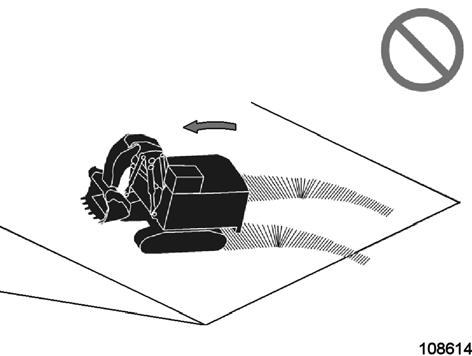
Do not travel the machine longer than 5 minutes with the final drives to the front (Fig. 2-241:). This will reduce the durability of the undercarriage and the travel system components.
Do not travel with a filled bucket (Fig. 2-242:).
If traveling down from a steep bench, do not place the bucket on the ground in order to prevent the machine from slipping or tipping (Fig. 2-243:). The weight of the machine will force the stick cylinders and the bucket curl cylinders over the relief valves causing them to extend into their end stops. The weight and inertia of the machine pressing on the cylinder – this could lead to overstressing cylinder clevis bolts.

Do not travel too steep ramps. Doing so can exceed the hydraulic capability of the machine. This can cause an uncontrolled state and damage to the machine. Refer to Operation and Maintenance Manual, section “Maximum Machine Inclinations” for information about maximum inclinations.

OMM
Operation
Always ascend the slope at a 90 degree angle (Fig. 2-244:).
Driving across the face of a slope or steering on a slope may cause the machine to slide or tip over.
Driving across the face of a slope or steering on a slope (Fig. 2-245:) may cause the machine to slide or tip over.

If the direction must be changed, move the machine to level ground, then, change the direction to ensure safe operation.
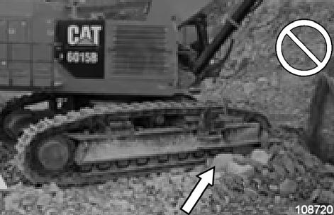
Do not travel through loose gravel material which could penetrate between rollers and track (Fig. 2-246:). This could result in damaging components of the under carriage.
Tracks may point load on rocks making the machine less stable.
Do not operate the machine in FAST travel speed unless in appropriate situations (Fig. 2-247:). Refer to the “Travel Speed – Recommendations –Table“ for further details.
Do not travel over large rocks or unblasted material. Large rocks can damage components of the under carriage (Fig. 2-248:).
Do not use the force of the bucket, the stick or the boom to lift and assist in turning the machine while the machine is traveling (Fig. 2-249:).
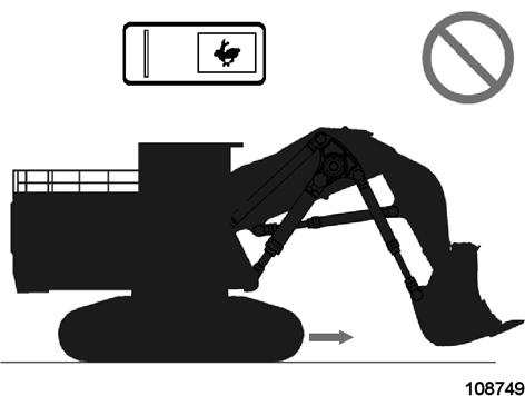
This technique is referred to as “jump steering”. Doing so creates the risk of high stress and damage to:
Swing ring and mounting bolts.
Bucket or shovel front clam and back wall
Undercarriage components.

For more information about correct turning the machine refer to section “Turning”.

Maximum Machine Inclinations
The machine must not exceed the inclinations indicated for working, traveling and servicing operations and during downtimes. The values specified in the tables below (next page) are valid for all types of attachment.
If the maximum inclinations are exceeded, there is a risk of severe damage to the engines due to insufficient lubrication. In the event of extreme inclinations the machine can topple over. The working performance of the machine is especially economical when the machine stands on firm and level ground.

A loss of performance and higher wear must be accepted when the machine works in an inclined position, e.g. when building a ramp or when slewing uphill.
For the building of ramps, the values specified in the table "Maximum inclinations during working operations" may be exceeded. In this case, however, a reduced service life of the components can be expected.
During downtimes, the machine must be parked in such a way that its inclination does not exceed 3° / 5.2 %.

Maximum machine inclinations during working operations:
Maximum machine inclinations during traveling:
The (theoretically) possible inclination is limited by the max. possible engine oil pan angle. Exceeding these limitations will cause severe damage to the engine.
Maximum machine inclinations during maintenance operations:
TRANSPORTING THE MACHINE Transport - Safety instructions
The machine must be loaded and transported only after all safety regulations have been observed and complied with.
Entrust loading and transporting of the machine to a company experienced in the transport of heavy equipment.
The responsability for loading and transporting lies with the transport company or their representative. Remove oil, grease, soil, mud, snow, ice and other materials from the hydraulic shovel's crawler tracks and from ramps and loading platforms of the transport vehicle to minimize slipping.
Secure the transport vehicle against rolling away. Use only tying equipment of sufficient strength (the weights and dimensions of the hydraulic shovel are set out in the "Technical specifications").
Transport
The dimensions and the service weight of the fully assembled hydraulic shovel do not allow the hydraulic shovel to be transported in an undismantled state on a low-bed trailer over public roads. Therefore, the following components and modules must be dismantled beforehand.
Suspensions points as well as the center of gravity are marked on the modules (see example, Fig. 2-250:).
Dimensions and weights of the machines modules can be found in the annex, chapter “Product Specification Sheet” as well as in the “„Service Manual“”. Detailed instructions for disassembling and assembling the machine can be found in the Service Manual.
RUNNING-IN INSTRUCTIONS FOR HYDRAULIC CYLINDERS
Compression of an oil/air compound in a hydraulic cylinder may result in detonations which might damage pistons and sealing rings.
Prior to initial commissioning and/or after repairs, run in the hydraulic cylinders as follows:
Switch on the electric motor.
The pressure-limiting valve in the hydraulic system must not respond
In the first two working cycles, retract and extend the pistons of the hydraulic cylinders to max. ½ to ¾ (not to the limit stop).
Never change direction suddenly. The waiting time between changes of direction must be at least 4 seconds.
In the next eight working cycles, retract and extend the pistons of the hydraulic cylinders to the limit stop. The waiting time between changes of direction must be at least 4 seconds.
When all hydraulic cylinders have been run in, the hydraulic shovel can operate at a higher engine speed
Emergency Lowering Of The Working Equipment
With the electric-motor not functional, the working equipment can be lowered to the ground as follows:
Sit down on the operator’s seat. Switch inside seat (105, Fig. 2-251:) is activated then.
Switch on the electric system with key-switch (32).
Operate switch (71), hydraulic servo system is activated then.
Operate switch (65, Fig. 2-252:) and hold.
Push control lever (116) forwards to lower the working equipment to ground.
Contact the responsible service personnel as soon as possible.
After Daily Operation
Parking the machine
Park the machine on level and stable ground. This is particularly important in winter to avoid freezing of the tracks.
Stand the working equipment on the ground.
Switch off the electric motor.
Shift both control levers into all directions todepressurize the hydraulic cylinders.
Withdraw the key from the electrical systemkey-switch.
Set the battery main switch to OFF.
Close the cab windows.
Lock the cab doors and all lockable hatches and covers on the machine.
Clean the machine of coarse dirt as well as of combustible and easily flammable substances, if possible with a stream jet (rubber parts and electric components with compressed air – refer to information label). Otherwise, the fire and explosion hazard will exist.
Inspect the hydraulic system, the track rollers, support rollers, idlers and gearboxes visually for leaks.
Escaping oil pollutes the environment.
Repair leaks immediately (or have them repaired).
Report oil accidents to the responsible person.
Check the superstructure, undercarriage and the working equipment for damage and all steel components for cracks or fractures.
Report detected damage immediately to the responsible person.
Clean off gross dirt, ice and snow from the fins and the fan wheel of the hydraulic oil cooler.
ASSEMBLING WORKING EQUIPMENT – SAFETY INSTRUCTIONS
Personel
Assembly work may be carried out only by operating or maintenance personnel who have the necessary know-how at their disposal.
If such know-how is lacking, meticulous instruction must be given by experienced personnel, e.g. from CGM-HMS GmbH .
The operating manual, and in particular the section headed “Fundamental Safety Instructions”, must have been read and understood.
Only such persons may start up the machine during assembly work in order to adjust the attachments.
Incorrect operation of the machine or the attachments may give rise to life-threatening situations.
Personal protective gear and working clothes
Wear closely fitting working clothing when working on the machine. Loose, wide garments may catch on machine parts and result in injury.
Wear your personal protective equipment: a safety helmet, safety goggles, safety footwear and gloves.
When carrying out work on the working equipment, f.ex. on the monobloc boom (Fig. 2-253:), use a fall arrester. Falling down from great hight may cause severe injuries. Connect the fall arrester to the safety line on the boom (arrow, Fig. 2-253:).
Tools and auxiliaries
Tools, hoists, slings, trestles and other devices must be in a reliable, safe state.
Metal splinters may cause injury when accessory bolts are being driven in or out. A brass or copper mandrel should therefore be used for this purpose, and goggles must be worn.
Use only the steps, platforms and handrails when climbing onto or off the machine.
Always keep steps and platforms in a non-slip state. Remove any oil, grease, earth, clay, snow, ice and other foreign matter immediately.
Securing the working equipment
Stand working equipment on the ground in such a way that no movements can be made if mechanical or hydraulic connections become detached. Secure any equipment or component which is to be mounted or dismantled, or whose position is to be changed, with hoists or appropriate slinging/supporting devices to prevent them from moving, slipping or falling inadvertently.
Securing the machine
Carry out work on the attachment only if the machine is secured as described in the “Securing the machine” section.
Selecting the attachments
The machine can be equipped with various attachments. The components of the attachments are assembled with hydraulic cylinders and connectors. Components can be combined in various ways for optimum adaptation of the attachments to the specific application.
Operate the machine only with the equipment and component combinations expressly approved by CGM-HMS GmbH for this type of machine.
Never install and commission other equipment and component combinations without CGM-HMS GmbH first having inspected and approved the project in writing.
Protective roof against falling objects
The machine is equipped with an integrated cabprotection roof (FOPS).
Securing the machine Risk of injury
The machine must not be started by unauthorized persons. Therefore, secure the machine. Observe the accident prevention regulations. Depressurize pipeline systems, on which work is to be carried out, by appropriate measures.
Protective shrouds of moving machine parts may only be opened or removed when the drive unit is stationary and protected against inadvertent starting.
Before carrying out fitting works, the machine and the equipment must be protected against inadvertent starting by placing chocks under the tracks and by standing the working equipment on the ground.
Hydraulic and lubricating systems
Close all open bores, pipe and hose connections with pressure-resistant plugs.
Refill collected hydraulic oil back into the hydraulic system only through the return-flow filters. Dispose of non re-usable oils without polluting the environment.
All components of CGM-HMS GmbH machines have been carefully purpose-coordinated. Troublefree operation and a long service life can only be achieved with original CGM-HMS GmbH spare parts.
Respect the sequence of working operations when fitting or replacing the attachments. The sequence has been determined and tested by qualified experts.
Secure the machine as described below:
before carrying out any fitting and modification work on the working equipment,
before carrying out any servicing and repair work on the machine.
Park the machine on level and stable ground.
Stand the working equipment on the ground.
Switch off the electric motor.
Depressurize the hydraulic system.
Withdraw the key from the key-switch.
CORROSION PROTECTION FOR PINS AND BEARINGS (BUSHINGS AND HUBS)
Use GLEITMO 815 anti-corrosive agent only.
Other agents are not approved by CGM-HMS GmbH.
All pins and bearings (bushings and hubs) of the working equipment or in equipment componenents must be treated GLEITMO 815 anti-corrosive agent before fitting.
GLEITMO 815:
permits easy fitting and dismantling,
protects against rust, oxidation and similar wear,
prevents seizing and fretting corrosion in nonmoving parts of bearings.
This is achieved by aluminium and copper particles forming a protective layer on the metal. This layer removes surface irregularities and does not sweat, seize or harden.
Part number of GLEITMO 815 is SAP 1519702. Available from CGM-HMS GmbH Spare-Parts Service.
Application of GLEITMO 815
Clean off grease, oil, dirt and corrosion protection agents from pins and bearings using white spirit or diesel fuel.
Rust patches must be thoroughly removed, if any.
All parts must present a dry, bright metal surface
Apply a thin layer of GLEITMO 815 on pins and all bearings using a brush or a spray can. Pin shafts and bearings must be completely covered by the protective layer.
If the protective layer of a pin already treated with GLEITMO 815 is damaged, these areas must be touched up before fitting the part.
Fitting and securing of pins
If the pin is too heavy to be fitted manually, apply GLEITMO 815 at first only on abt. A quarter of the pin’s length Then position pin by means of a lifting gearready for fitting. Apply GLEITMO 815 on the remaining length of pin shaft, fit pin and secure.
ON-BOARD CRANE (OPTIONAL)
The on-board crane is designed for lifting heavy parts only.
Do not lift persons.
Observe all national directives as well as specific regulations relevant to crane operation.
Personel
Crane work may be carried out only by operators who have the necessary know-how and the permission to operate cranes.
If such know-how or such permission is lacking, meticulous instruction must be given by experienced personnel, e.g. from CGM-HMS.
Incorrect operation of the crane may give rise to life-threatening situations.
On-board crane, monitoring, warning and control elements
On-board crane, putting into operation
Risk of serious injuries due to movements of the crane.
Put the crane into operation only after all persons have left the danger area. Do not exceed the maximum lifting capacity (observe the lift capacity chart attached to the boom).
Prior to each deployment: Carry out all maintenance work as listed in the “Inspection and Servicing Plans “T” and “W”.
To start the drive unit:
Turn key-switch (5, Fig. 2-254:) to position ON.
Press button (6), engine will start.
The crane control unit is equipped with an Emergency OFF push switch (11).
In case of emergency push switch, the engine of the drive unit comes to standstill.
After finishing work block the boom, then stop the engine (see chapter “On-board crane, - blocking the boom in position of rest”).
On-board crane, drive unit
The drive unit (Fig. 2-255:) supplies the crane with hydraulic power. So the on-board crane is functional without the shovel’s engines running.
The drive unit comprises the diesel engine, fuel tank, starter batteries and the hydraulic system.
The drive unit is equipped with an Emergency OFF push switch (arrow, Fig. 2-255:).
In case of emergency push switch, the engine of the drive unit comes to standstill.
On-Board crane, – blocking the boom in position of rest
Movements and accelerations produced by working operations of the machine can cause damage to the swing drive of the on-board crane, if the crane is not blocked.
The hydraulic on-board crane must therefore be blocked in its position of rest.
Risk of serious injuries due to movements of the crane.
Put the crane into operation only after all persons have left the danger area.
To block the boom:
Retract the boom completely.
Swing the boom in the direction of the blocking device (Fig. 2-256:) and lower it.
Withdraw the cotter pin at the tip of the boom.
Extend the boom carefully until the tip engages the blocking device (arrow, Fig. 2-256:).
Reinsert and lock the the cotter pin.
On-board crane, checking Extract from the inspection and testing regulations
The on-board crane is approved in accordance with the Accident Prevention Regulations for Cranes (BGV D6, applicable only in Germany).
The on-board crane must be inspected regularly in accordance with the regulations in force in the country of use.
The inspections must be requested by the user of the crane. The expert or specialist entrusted with the inspection can be appointed at the user’s discretion.
The user must ensure, however, that the appointed person meets the requirements.
The user is obliged to make available all documents required for the inspection and to ensure the smooth running of the inspection. He is furthermore obliged to provide, if required, crane operators and auxiliary personnel and the required test loads.
The result of the inspection is to be documented in an inspection record signed by the inspector.
The inspection record serves as proof on the part of the user that the inspections have been carried out. The inspection record must contain all data required for crane identification and for the performance of further regular inspections.
Monitoring cameras
This hydraulic shovel is equipped with two monitoring cameras:
one mounted on the counterweight, looking backwards;
one mounted on the hydraulic oil cooler module, looking to the right.
The two cameras and the belonging LCD-diplay are operational after the electrical system of the machine has been activated with the key operated switch.
Both cameras transmit their images to the same LCD-display. The display is mounted near the control column.
For toggling between the camera images beeing displayed, press the key in the left joystick (arrow, Fig. 2-257:).
Additional information can be found in the manuals of the camera manufacturer (see Volume 5 of the Technical Documentation “Components”).
Operation and Maintenance Manual Target group
Part 1 INTRODUCTION
FUNDAMENTAL SAFETY INSTRUCTIONS
Part 2 OPERATION
Operating personnel +
Inspection and servicing personnel
Repair personnel
Operating personnel
The operating personnel must have knowhow relevant to the operation and the application of this or comparable machines.
Part 3 INSPECTION AND SERVICING
Inspection and servicing personnel
The inspection and servicing personnel must have know-how relevant to the inspection and servicing of this or comparable machines.
Part 4 REPAIR WORK
Repair personnel
The repair personnel must have know-how and experience relevant to the repair of this or comparable machines.
Part 5 ANNEX Operating personnel +
Inspection and servicing personnel
Repair personnel
Part 6 INDEX Operating personnel
Inspection and servicing personnel
Repair personnel
Safety Instructions For Hydraulic Shovels With Electric Motor
Maintenance and inspection work on electrical systems may only be performed by qualified electricians or by workshops employing such personnel.
A qualified electrician for the purpose of this regulation is a person who has the corresponding technical training, know-how and experience as well as knowledge of the pertinent prescriptions and who is therefore in a position to judge the work entrusted to him and the potential dangers in connection therewith.
Before carrying out any maintenance and inspection work on the electrical system, the following precautions must be taken:
In the transformer station
Cut out the supply voltage
Secure against switching on; apply a warning sign.
Check that the electrical system is off circuit.
Connect to earth and short-circuit.
Protect adjacent and live parts against accidental contact.
On the hydraulic shovel
Cut out the circuit breaker (see the “ Switching off the circuit breaker “ chapter in part 2 of the present Operation and Maintenance Manual)
Secure circuit breaker against switching on, apply a warning sign
Switch off the earthing switch (see manufacturers Operating Instructions).
After finishing inspection and maintenance work:
In the transformer station
Disconnect the earthing and short-circuiting line.
Unlock the safety device preventing switch-on; remove the warning sign
Remove the partitions.
Switch on the supply voltage.
On the hydraulic shovel
Unlock the safety device preventing switch-on; remove the warning sign
Switch on the circuit breaker, (see the “ Switching on the circuit breaker “ chapter in part 2 of the present Operation and Maintenance Manual).
On the hydraulic shovel
Disconnect the earthing and short-circuiting line.
Withdraw the partition.
Fasten cover.
INSPECTION AND SERVICING –SAFETY INSTRUCTIONS
Operation and Maintenance Manual
No inspection and servicing work must be carried out until the Operation and Maintenance Manual has been read and understood.
Pay special attention to:
Fundamental safety instructions” and all warnings and safety instructions attached to the machine. The Operation and Maintenance Manual lists all jobs to be done. The descriptions of job sequences, however, provide only experienced personnel with the necessary instructions.
The Operation and Maintenance Manual must be kept with the machine at all times.
Inspection and servicing personnel
Inspection and servicing personnel must have the necessary know-how on the inspection and servicing of this or comparable machines.
The necessary know-how can be acquired in a several day’s instruction, e.g. by a CGM-HMS GmbH mechanic or by attending a CGM-HMS GmbH training course.
Personal protective equipment and working clothing
Wear closely fitting working clothing when working on the machine. Loose, wide garments may catch on machine parts and result in injury. Wear a safety helmet, safety footwear, gloves and, in the event of high noise levels, ear protectors.
Securing the attachment
Stand attachment on the ground in such a way that no movements can be made if mechanical or hydraulical connections become detached.
Secure any equipment or component which is to be mounted or dismantled, or whose position is to be changed, with hoists or appropriate slinging / supporting devices to prevent them from moving, slipping or falling inadvertently.
Securing the machine
Carry out servicing work only if the machine is secured as described in the section “Securing the machine”.
Climbing onto and off the machine
Use only the ladders, steps, platforms and handrails provided when climbing onto or off the machine.
Always keep ladders, steps, platforms and handrails in a non-slip, safe state and remove any oil, lubricant, soil, clay, snow, ice and other foreign matter immediately.
Always maintain a three point contact with the steps and the grab handles.
Always face the machine when climbing on and off.
Checking the state of tools
Use only fully functional, reliable tools. Select the right tool for the job. Wrenches of the wrong size, for example, may slip and cause injury.
Cleaning jobs
Prior to commencing work, clean your working area, if necessary and possible, with a stream jet (rubber parts and electric components with compressed air – refer to information label).
Use only lint-free cleaning rags when working on the hydraulic system.
Cleaning agents and solvents may give off harmful, readily flammable vapours. Never work with such agents except on well ventilated premises; never inhale the vapours and never smoke. Prevent solvents and cleaning agents from coming into contact with your skin.
Wear gloves.
Observe the instructions on the packaging.
Handling flammable liquids
When handling flammable liquids:
never smoke,
keep away from unshielded light sources and naked flames,
Consumables often have low flash points and are readily ignited. Never attempt to extinguish burning liquids with water.
Use:
dry powder,
carbon dioxide or
foam extinguishers.
Water used for extinguishing purposes would vapourize instantaneously on contact with burning substances and spread burning oil, for example, over a wide area. Water generates short circuits in the electrical system, possibly producing hazards. Notify the fire brigade.
Fastening and securing elements
Check fastening and securing elements, e.g. bolts, nuts, washers, before using them again. Replace any damaged parts.
Spare parts
Use only the original sparts parts of CGM-HMS GmbH .
They are the only ones to fulfill the technical specifications of the machine.
Handling oils and lubricants
Hot lubricant or hydraulic oil emerging uncontrolled from the system may result in severe burns. Never set foot withing reach of the emerging oil jet. Avoid contact with the skin. Wear gloves and firm protective clothing.
Used oil may be harmful to the skin. Clean soiled skin thoroughly with warm soapy water and apply a barrier cream. Never use fuels or solvents for cleaning the skin.
If you have swallowed any oil, avoid vomiting but consult a doctor immediately.
Visible oil losses
Have any visible leakage repaired immediately. Escaping oil is an environmental hazard.
Soak up any oil that has escaped with a binding agent.
Sweep up binding agent and dispose of it separately from other waste.
Relieving residual pressure in the hydraulic system
Only unpressurized hydraulic systems may be opened. Even when a machine is parked on a horizontal surface with ist attachments supported on the ground and its electric motor switched off, there may still be substantial residual pressure in parts of the hydraulic system, e.g. primary pressure from the last hydraulic movements prior to stopping the machine.
Residual pressure is reduced only gradually. If an intervention into the hydraulic system is to be undertaken immediately after stopping, the system must be depressurized:
(Do not leave the operator’s seat)
Stand attachment on the ground,
Switch off the electric motor,
Move all control levers and pedals repeatedly into all directions.
For more detailed information on depressurizing hydraulic sections please refer to the Service Manual, chapter 8.
Bolted connections, piping, hydraulic hoses
Repair any leakage in the piping and hose system immediately.
A fine, highly pressurized jet of hydraulic oil can penetrate the skin.
Never search for leakages with the fingers, but use a piece of cardboard and always wear goggles. If oil has penetrated into the skin, consult a doctor immediately.
Never repair damaged piping; always replace them.
Replace hydraulic hoses immediately on detecting any damage or moist areas.
Tighten leaking screw plugs only when the system is depressurized.
Escaping oil is an environmental hazard.
Non-polluting disposal
Dispose of oils, lubricants, cooling liquids, detergents, solvents and oil-containing components, such as filters, cleaning rags, replaced wearing parts and unusable machine parts, without polluting the environment and separately from other waste.
Do not dispose of these substances together with household wastes.
Fill these substances into the containers provided for such purposes.
Like any other oil, also bio-degradable, “environmental-friendly” hydraulic oil must be disposed of separately.
Do not allow oils and oily wastes to penetrate into the soil or into water. They are an environmental hazard
Sealing elements
After replacing parts or after opening housings replace seals.
Always use new seals and gaskets. Clean sealing faces prior to assembly. Check sealing elements prior to installation and replace any that are even slightly damaged. When assembling, ensure a perfect fit.
Handling batteries
California Proposition 65 Warning Battery Posts, terminals and related accessories contain lead and lead compounds, and handling batteries may also exposure you to sulfuric acid mist, chemicals known to the state of California to cause cancer and reproductive harm. Wash hands after handling.
Batteries give off explosive gases.
Never handle batteries close to naked flames and unshielded light sources, never smoke.
Battery acid is toxic and corrosive.
Avoid any contact with the skin, mouth, eyes and clothing. Avoid spilling battery acid or inhaling the vapours.
Wear gloves, firm protective clothing and goggles when handling batteries.
If the skin is splashed with acid, rinse thoroughly with running water and consult a doctor.
If the eyes are splashed with acid, rinse thoroughly with running water and consult a doctor immediately.
Never set tools down on the battery. They may induce a short circuit, causing irreparable damage to the battery and injuring persons.
Never wear metal necklaces, bracelets or watchstraps when working on the battery. The metal parts may induce a short-circuit resulting in burns. Dispose of used batteries separately from other waste in the interests of environmental protection.
Before working on the electrical system
Before performing work on the electrical system where tools, spare parts, etc. can come into contact with electrical conductors or contacts, the battery must be disconnected.
Disconnect first the negative and then the positive terminal.
After the work: Reconnect first the positive and then the negative terminal.
Selecting oils and lubricants
Use the recommended qualities only, matching viscosities with the temperature level.
Filters
Replace / clean all filter elements or filter cartridges within the specified periods.
All filters are coordinated carefully with the equipment. Original CGM-HMS GmbH parts must be used to ensure smooth running and a long service life of the engine and the hydraulic units.
Oil-level check and oil change
Position the machine horizontally. Change the oil when the machine is at operating temperature. Warm oil flows better and carries suspended particles (carbon or abraded matter) better.
Lubricating
Clean the lubricating nipple, then lubricate as scheduled.
After servicing
To prevent corrosion, coat all bright metal parts with a lubricant film.
On completing work, re-install all protective devices.
Never switch on the electric motor while work is being done on the machine. Carry out performance tests with the machine.
FIRE AND EXPLOSION HAZARD Safety Instructions
Avoid smoking and open fire on, next to and below the machine.
Combustible and easily flammable substances or liquids increase the fire and explosion hazard. Do not store such substances on the hydraulic shovel.
Clean the hydraulic shovel thoroughly, if possible, with a steam jet (rubber parts and electric components with compressed air – refer to information label), when, for example, oil, lubricant, fuel or cleaner was spilled.
Such substances may spontaneously ignite if they get into the vicinity of hot units. Even battery gases can ignite in open flames or fire.
Avoid parking the hydraulic shovel in places where
combustible substances such as coal dust or tar are present.
open or smouldering fire may occur.
Remove the hydraulic shovel from such an area where combustible or easily flammable liquids have spilled from the hydraulic shovel onto the ground.
Flying sparks may cause fire on the ground that can spread to the hydraulic shovel.
INSPECTION AND SERVICING PLANS – INSTRUCTIONS Servicing Intervals
The inspection and servicing plan lists all jobs which have to be done on the machine at regular intervals.
The individual inspection and servicing plans are marked with letters providing a link between the operating hours (OH) recorded by the hours-run meter of the machine and the inspection and servicing plans.
Plan Do all jobs ….
V …once prior to initial commissioning.
N …after initial commissioning and during the running-in period (after 100 OH).
T …every 10 OH or every working shift
1)
W …every 60 OH or weekly .2
B …after every 500 OH.
C …after every 1000 OH.
D …after every 5000 OH.
E …after every 10000 OH.
OH = Bh = Operating hours 2 Whichever
Oils / Lubricants
For the specification of oils and lubricants to be used refer to the “LUBRICANTS / CONSUMABLES” section.
The numerals mentioned in the “Oil / Lubricant” column in the inspection and servicing plans have the following meaning:
I Oils for combustion engines and compressors
II Oils for hydraulic systems
IIIa, b Oils for gearboxes
V Lubricants for bearings and swing rings
Cleaning jobs
Cleaning jobs, especially on cooling systems, must be done at shorter intervals if the machine is exposed to severe dust build-up.
Components
The maintenance intervals for components, e.g. electric motor and gearboxes, are listed in the following CGM-HMS GmbH maintenance schedules. It is possible that the manufacturer’s documentation for these components states intervals deviating from the above-mentioned intervals.
In such case, only the maintenance intervals specified by CGM-HMS GmbH shall apply.
Plan V
Plan V – Once prior to initial commissioning
Plan V – Once prior to initial commissioning
Plan N
Plan N – After initial commissioning and during the running-in period (after 100 OH) Page 1 of 2
Electric motor
-Electrical parameters are maintainedCheck
-Permissible bearing temperatures not exceeded Check
-Smooth running characteristics and machine running noise not deteriorated Check
-Motor foundation
(For more information refer to Electric Motor
Operating Instructions, chapter 9)
Electrical system
Medium-voltage cells
-mechanical connections
-lines
-terminals and plug connections
Hydraulic system Hydraulic
Check for cracks and indentations
Check for tightness
Check for tightness
Check for tightness
3 see “Refilling quantities – Oil“ table
Plan N – After initial commissioning and during the running-in period (after 100 OH) only)
(for tightening torques see “Service
- Fastening bolts
Swing ring
-Fastening bolts (swing ring, undercarriage and upperstructure)
Cable guide for power supply cable
-Fastening bolts cable guide / machine
Cable reel (if equipped)
-Fastening bolts at reel, cable guide, drive motor, switchgear cabinet
-Fastening bolts cable reel / undercarriage
Undercarriage
Fastening bolts
-carbody – trackframe, -bottom rollers – trackframe, -top rollers - trackframe
Upper structure
-Fastening bolts, especially at upper structure / pedestal / operator´s cab
All lines, fittings and connections
Check for tightness (for tightening torques see “Service Manual”)
Check for tightness (for tightening torques see “Service Manual”)
Check for tightness (for tightening torques see “Service Manual”)
Check for tightness (for tightening torques see “Service Manual”)
Check for tightness (for tightening torques see “Service Manual”)
Check for tightness (see “Service Manual” for tightening torques)
Check for tightness (for tightening torques see “Service Manual”)
Inspect visually for leaks, wearing marks
Plan T and W
Plan T - Every 10 OH or every working shift (whichever comes first)
Plan W - Every 60 OH or every working week (whichever comes first)
EM028480-01
OMM 6060AC, 6060ACFS(3 847 036.00)-EN
Plan T - Every 10 OH or every working shift (whichever comes first)
Plan W - Every 60 OH or every working week (whichever comes first)
Plan A – E
Plan A - after every 250 OH (at 250, 750, 1250 ... OH)
Plan C - after every 1000 OH (at 1000, 2000, 3000, 4000 ... OH)
Plan E - after every 10000 OH (at 10000, 20000, 30000, ... OH)
Plan B - after every 500 OH (at 500, 1500, 2500 ... OH)
Plan D - after every 5000 OH (at 5000, 15000, 25000 ... OH)
9) accessible places for rust, remove rust.
5 apply a thin layer of low temperature lubricant
6 Check for alignment after every 2000 OH (These are works done by specialists using special tools, please contact your Cat dealer)
Plan A - after every 250 OH (at 250, 750, 1250 ... OH)
Plan C - after every 1000 OH (at 1000, 2000, 3000, 4000 ... OH)
Plan B - after every 500 OH (at 500, 1500, 2500 ... OH)
Plan D - after every 5000 OH (at 5000, 15000, 25000 ... OH)
Plan E - after every 10000 OH (at 10000, 20000, 30000, ... OH) Page
Plan A – after every 250 OH (at 250, 750, 1250 … OH)
Plan C – after every 1000 OH (at 1000, 2000, 3000, 4000 … OH)
Plan E – after every 10000 OH (at 10000, 20000, 30000, … OH)
Plan B – after every 500 OH (at 500, 1500, 2500 … OH)
Plan D – after every 5000 OH (at 5000, 15000, 25000 … OH)
EM028480-01
7 see “Refilling quantities – Oil“ table
8 Unless it is regulary analyzed, the hydraulic oil must be changed every 5000 OH or after 3 years at the latest
Plan A - after every 250 OH (at 250, 750, 1250 ... OH)
Plan C - after every 1000 OH (at 1000, 2000, 3000, 4000 ... OH)
Plan E - after every 10000 OH (at 10000, 20000, 30000, ... OH)
EM028480-01
OMM 6060AC, 6060ACFS(3 847 036.00)-EN
Plan B - after every 500 OH (at 500, 1500, 2500 ... OH)
Plan D - after every 5000 OH (at 5000, 15000, 25000 ... OH)
Plan A – after every 250 OH (at 250, 750, 1250 … OH)
Plan C – after every 1000 OH (at 1000, 2000, 3000, 4000 … OH)
Plan E – after every 10000 OH (at 10000, 20000, 30000, … OH)
Plan B – after every 500 OH (at 500, 1500, 2500 … OH)
Plan D – after every 5000 OH (at 5000, 15000, 25000 … OH)
Plan A - after every 250 OH (at 250, 750, 1250 ... OH)
Plan C - after every 1000 OH (at 1000, 2000, 3000, 4000 ... OH)
Plan E - after every 10000 OH (at 10000, 20000, 30000, ... OH)
Plan B - after every 500 OH (at 500, 1500, 2500 ... OH)
Plan D - after every 5000 OH (at 5000, 15000, 25000 ... OH)
If any suspect areas have been found additional testing is required: detailed crack analysis prepare the surface of the relevant area to be inspected and carry out the dye penetrant, magnetic powder or ultrasonic test.
10 Do all servicing jobs at least once a year and when necessary
11 see “Refilling quantities – Oil“ table
12 „Structural Inspection Reports“ for inspections every 500 OH can be downloaded from the CGM-HMS GmbH website www.bucyrus-HEX.de, section „Support, Warranty“.
OMM 6060AC, 6060ACFS(3 847 036.00)-EN
Lubricating chart – Lubricant (legend)
All other greasing points are supplied with lubricated by the central lubricating system.
Filling quantities – Lubricant
rollers supported with lubricant via the central lubrication system for the undercarriage)
13 see "LUBRICANTS / CONSUMABLES" section
14 apply a thin layer of low temperature lubricant
EM028480-01
OMM 6060AC, 6060ACFS(3 847 036.00)-EN
Inspection plan – Oil (legend)
15 see "LUBRICANTS / CONSUMABLES" section
16 Change hydraulic oil every 5000 OH unless the oil is analyzed at regular intervals, but not later than every 3 years.
17 Change oil at least once a year.
18 Change hydraulic oil at least once a year.
Filling quantities - oil
Filling quantities - other
Lubricants
Notes on the selection of oils and lubricants
Original CGM-HMS GmbH oils and lubricants
Besides regular and careful maintenance, the quality of the oils and lubricants used in the machine has a decisive influence on high performance, reliability and long service life of a machine and of its units and assemblies.
The lubricants tables in the CGM-HMS GmbH Operation and Maintenance Manual contain specifications for the oils and lubricants that are approved for use in CGM-HMS GmbH machines. These oils and lubricants are especially adapted to CGMHMS GmbH machines and their units and assemblies.
Other oils and lubricants which do not fulfil the requirements of the specifications can be the cause of premature wear or of damage to and failures of machine units and assemblies.
For this reason, CGM-HMS GmbH only approves the use of the specified oils and lubricants. All other qualities are not approved.
CGM-HMS Hydraulic Fluid
Caterpillar is not in a position to evaluate the many types of fluids promoted by other manufactures and their effect on Caterpillar products. The use of these products is at the discretion of the customer who assumes all risks for the effects that result from this usage.
The CGM-HMS Hydraulic fluid that is provided as a factory fill for the HMS has been evaluated for fluid compatibility when adding or topping off with the Caterpillar HYDO Advanced product. The 2 fluids are compatible and can be used. Follow the maintenance interval schedule and for fluid sampling that is stated in the Operation and Maintenance Manual for your machine. To have the full benefit of the properties of either fluid the cross contamination should be kept to 10% or less. With a greater cross contamination the full benefit of either of the fluids may not be realized so it is important to monitor the fluid properties regularly. For additional details about Cat HYDO Advanced and Caterpillar’s fluids recommendations, please refer to Special Publication SEBU6250, “Caterpillar Machine Fluids Recommendations” and publication EM027744, “Fluid Specifications HMS” which may be found on the Web at SIS.Cat.com.
Although the lab testing has shown compatibility between the BM Hydraulic fluid and the Cat Hydo Advance, we are not able to test every situation and condition with the fluid mixtures and would recommend that the fluid be changed out to eliminate any fluid incompatibility issues.
Alternative oils and lubricants
The oils and lubricants filled into the machine must meet at least the specifications mentioned in the lubricants tables of the CGM-HMS GmbH Operation and Maintenance Manual.
In the event of damage to the machine or to its units and assemblies caused by the use of alternative oils and lubricants that are not compatible with CGM-HMS GmbH specifications, CGM-HMS GmbH does not assume any responsibility and does not accept any warranty claims.
LUBRICANTS / CONSUMABLES
I. Oil for combustion engines (On-Board Crane, option)
II. Oil for hydraulic system (selection)
III.a Oil for pump gearboxes and travel gearboxes
III.b Oil for swing gearboxes
V. Lubricant for bearings, swing rings and track system (Central lubrication system)
Lubricants for idlers, track rollers and upper rollers (Lifetime lubrication)
Servicing Work
Hose line for oil changes
Collect escaping oil and cooling liquid and discard without polluting the environment.
Carry out oil changes when the machine is at operating temperature; warm oil drains away more easily.
Filling and draining is can be done by means of a hose through the service station (Fig. 3-9:).
For filling and draining, a flexible hose is connected to the express coupling on the service station and to the service vehicle at the other end.
The filling operations require an overpressure, whereas the draining operations require low pressure.
The the swing gearboxes are equipped with automatic drain valves (1, Fig. 3-10:)
These automatic drain valves permit oil changes without polluting the environment.
Fig. 3-10:
Change oil as follows:
Place a collecting recipient for used oil under the corresponding automatic drain valve. For the recipient capacity refer to the "Re-filling quantities - Oil" table or to the "Refilling quantities - Other" table.
Unscrew protective cap from automatic drain valve.
Screw on hose line (2) to open the valve, so that the oil or the cooling liquid can flow out.
When the oil has drained away, unscrew hose line to allow the valve to close automatically.
Screw protective cap back in place.
Electric Motor
Electric motor - Safety instructions
Read and observe: "Inspection and Servicing – Safety Instructions" and the electric motor Operation and Maintenance Manual.
Secure the machine as described in the "Securing the machine" section.
Wear protective gloves and firm working clothing.
Switch off electric motor, to do so actuate switch (42, Fig. 3-11:).
Set servicing switch (4, Fig. 3-12:) to locked position and secure in this position with a padlock.
Cleaning the electric motor
Clean the electric motor, the cooling fins, bearing shields and ventilators from dust with compressed air, brushes and clothes only.
Remove the fan guard before cleaning the ventilator fan. Install it after cleaning.
Don't damage the protective coating while cleaning the electric-motor.
For more information see the manufacturers manual for the electric motor.
It is not permissible to clean the electric motor or any live hydraulic shovel components with a steam cleaner and steam jet.
After finishing work on the electric motor remove the padlock from servicing switch (4, Fig. 3-12:) and unlock.
Electric motor, greasing
Read and observe: "Inspection and Servicing – Safety Instructions" and the electric motor Operation and Maintenance Manual.
Secure the machine as described in the "Securing the machine" section. Wear protective gloves and firm working clothing.
During greasing the electric motor must be switched on. Be extremely careful to rotating parts.
Lubricate the bearings of the electric motor in regular intervals (see plates on the electric motor, sample is shown in Fig. 3-13:).
Press in the correct quantity of lubricant specified on plate (Fig. 3-13:).
When the electric motor is at standstill, remove the old, used lubricant from the bearing housing.
Additional information on servicing the electrical motor is given in the electric motor Operation and Maintenance Manual from the motor manufacturer. Up to 30 minutes after greasing the temperature of the bearings might heavily increase. Thereafter the temperature decrease to normal. This is normal, the procedure is monitored on the BCS display.
Additional servicing work
All servicing and maintenance work not described here are carried out by the CGM-HMS GmbH after sales service resp. by the Service Dept. of the manufacturer of the electric motor. (see electric motor Operation and Maintenance Manual).
Electrical System
Electrical system - Safety instructions
Read and observe the "Inspection and servicing – Safety instructions" chapter.
Interrupt electrical circuits with the circuit breaker before start working on the electrical system. All electric lines upwards from the circuit breaker are then without voltage (refer to the "Safety instructions for hydraulic shovels with electric motor" at the beginning of this chapter).
Before starting live-line servicing work e.g. measuring and testing with voltage applied, press switch (4, Fig. 3-14:) and secure it with a padlock. Now voltage is supplied to the whole system but the electric motor can not be switched on.
This prevents accidents, inadvertent starting of the electric motor, and short circuits.
The 24V circuits are energized by the two batteries when the circuit breaker is switched off. These lines can also be de-energized with the battery main switch. Shut off the electrical system with the battery main switch when carrying out repair work or during prolonged downtimes of the hydraulic shovel.
Gas-discharge lamps in Xenon working lights are operated with high voltage.
Risk of injury caused by battery acid and gases. Wear goggles, working gloves and firm working clothing.
Carry out voltage and continuity checks only by means of a test lamp or a measuring instrument. Do not check by "touching ground" with a bare wire. The short-circuit thus produced damages the alternator and the electronic modules of the PMS. The electrical circuit diagrams are annexed to the spare-parts list. Further information can be found in the CGM-HMS GmbH Service Manual "Working with circuit diagrams".
Cables and cable lugs must not get in contact with other metal parts. Replace broken or damaged cables and the respective cable lugs.
If a bulb does not work after replacement, the pertaining fuses, connection cables and contacts must be checked.
Battery, checking state of charge
Warning! Battery Posts, terminals and related accessories contain lead and lead compounds, chemicals known to cause cancer and reproductive harm. Risk of injury caused by battery acid and gases.
Wear goggles, working gloves and firm working clothing.
Do not eat, drink or smoke when handling batteries.
Wash hands after handling.
Read and observe the "Inspection and servicing – Safety instructions" chapter.
Checking the battery fluid level
(Not applicable in case of maintenance-free batteries)
Unscrew caps (Fig. 3-15:).
If checking inserts are provided, the battery acid must reach up to their bottom.
If no checking inserts are provided, insert a clean wooden rod into the battery until it contacts the upper edge of the cell plates. The rod must be moistened over at least 10 mm / 0.4".
If the fluid level is too low, top up with distilled water only
Checking charge of the battery
The acid temperature must be 20 ° C / 68°F.
Unscrew caps of the battery (Fig. 3-15:).
Measure the acid density of the battery using a commercial acid tester (Fig. 3-15:).
The acid density measured is in direct correlation with the battery charge. Acid half charged, recharge discharged, recharge immediately
On closed / sealed (so called „maintenance-free“) batteries, the charging status can be checked using a charge meter. Ask your Caterpillar dealer for assistance.
Charging the batteries
The batteries are charged by the battery charger only if the electrical system with the circuit breaker is switched on.
Removing and installing the battery
Read and observe the "Inspection and servicing – Safety instructions" chapter.
Wear protective gloves and firm working clothing. Switch off the electric motor before removing the batteries.
Turn key in key-switch to position "0" and withdraw.
Set battery main switch to “OFF“ position. Disconnect and reconnect the terminal clamping lugs in the prescribed order.
Disconnecting and connecting in the wrong order may cause short-circuits.
The batteries (1, Fig. 3-16:) are located in the pedestal (cab module). The 12-volt batteries are connected in series and in parallel, so that the system voltage is 24 volts.
Fig. 3-16:
Detach battery holder (3).
Disconnect the cable lug from the negative terminal of the battery.
Disconnect the cable lug from the positive terminal of the battery.
Insulate the cable lugs.
Lift battery out of battery box.
Before installing new batteries, the contact faces of the battery terminal posts and the cable lugs must be cleaned down to the bright metal.
Install the new batteries.
Connect the cable lug to the positive terminal of the battery. Tighten the clamping bolts of the cable lugs. Do not use too much force to avoid deformation.
Connect the cable lug to the negative terminal of the battery.
Apply special terminal lubricant or acid-free vaseline on the battery terminal posts and clamping lugs. Loose or corroded clamping lugs will lead to alternator or regulator overloading
Electrical system, control cabinets
The electrical system control cabinets are located in the cab module and in the motor compartment. The cabinets are described in the spare-parts list (electrical circuit diagram) together with the designation of the electrical components.
Breather filter
In the control cabinets
For the 7200 V power supply,
For the 400 V system,
For the 24 V system, the air is drawn in and cleaned by a ventilator with filter.
Emptying the dust trap
Press dust trap (14, Fig. 3-17:) and hold until the dust trap is empty.
Emptying the dust collector
Loosen clips (11, Fig. 3-17:).
Remove dust collector (12) and empty.
Filter element, clean / replace
Remove dust collector (12, Fig. 3-17:).
Withdraw filter element (13, Fig. 3-18:).
Replace or clean filter element (13).
Refit dust collector (12, Fig. 3-17:).
Checking and cleaning the filter element
Check the filter paper of the element by inserting a lamp into the element (Fig. 3-19:). Any damage can then be seen
Replace damaged or distorted element immediately.
Check element seal. If damaged, replace filter element too.
Cleaning with compressed air allows the filter element to be re-used immediately.
Blow filter element (Fig. 3-20:) dry with compressed air by moving the compressed-air piston up and down inside it. The pressure at the nozzle must not exceed 3 bars / 43psi
Cleaning is completed when no more dust is seen to leave the filter element.
Never clean filter element by beating it against hard objects.
Replace main filter element after 1000 operating hours or 3 cleaning cycles, but not later than after one year of operation.
Replacing filter mats
A filter mat is installed in the control cabinets behind the cover.
Check filter mats visually and replace if necessary.
Draining water from the switchgear cabinet
Check control cabinets for condensation.
Unscrew drain plugs and drain off water.
The base of the control cabinets must be kept clean.
Slip ring assembly, servicing work
(Fig. 3-21:)
Switch off power supply at the transformer station.
Check that the slip ring assembly is without tension before opening it.
Read and observe the "Inspection and servicing – Safety instructions" chapter as well as the chapter “Electrical system, safety instructions”..
Observe the Servicing Instructions of the slip ring manufacturer.
Remove all tracks of dirt.
There is a transparent sideplate at the housing. Check the housing inside for wear debris coming from the brushes and for lubricant. Remove if necessary.
Clean insulators and check for damage.
Check condition of slip ring contact surfaces; remove any sign of oxydation, "splatter" or burn spots. Then coat with contact lubricant.
Check carbon brushes for signs of wear. (See Servicing Instructions of the slip ring manufacturer).
Electrical circuit diagrams
The electrical circuit diagrams and wiring diagrams are annexed to the spare-parts list. Further information can be found in the CGM-HMS Service Manual "Working with circuit diagrams".
Replacing fuses
Fuses and their function are listed on a sheet inside the switch-cabinets in the cab module. Use only original fuses with the specified current rating.
Replacing lamps and bulbs
If a bulb does not work after replacement, the pertaining fuses, connection cables and contacts must be checked.
Xenon-working floodlights are operated with high voltage.
Read and observe the chapter: “Floodlight projector, replacing the lamp”.
Floodlights working with LED-technology do not have replaceable lamps / bulbs. The floodlight must be replaced if defective.
Xenon floodlight projector (if equipped), replacing the lamp
Safety instructions
The floodlight projectors use xenon technology. The lamp is not a usual incandescent lamp, but a gas discharge lamp which is operated with a ballast unit. The ballast unit is integrated in the floodlight projector.
When the projector is turned on, the ballast unit generates a high-voltage pulse of more than 25000 volts to start the xenon lamp.
Warning!
This high-voltage pulse can be a lifethreatening risk, if a person comes into contact with any of the live components. This can be the case, for instance,
if the lamp is operated improperly,
if the projector housing is opened in an inapropriate way or
by sticking one's hand into an opened or damaged projector.
Protect yourself from potential risks by reading and by observing the following safety instructions.
Always switch off the projector and disconnect it from its power supply before replacing the Xenon lamp. Allow the xenon lamp to cool off before removing it from the projector. Wear googles and safety gloves when replacing the lamp.
Never stick your hand into the lampholder. The contacts may still be live with residual voltage.
Never switch on the projector when the xenon lamp has been removed. There is a risk of voltage discharge and damage to the lampholder.
The glass body of the xenon lamp is filled with different gases and metal gases and is under gauge pressure (risk of injury from splinters)
If the xenon lamp breaks apart in closed room (workshop), all persons must leave the room and the room must be ventilated for at least 20 minutes to exclude any health risks caused by gases.
Further instructions
Always hold the xenon lamp by the base. Never touch the glass bulb. Sweat and lubricant from the skin would evaporate when the lamp is in operation and obscure the reflector.
If the fingers have nevertheless come into contact with the glass bulb, the fingerprints must be removed with a clean cloth and some alcohol. The replaced Xenon lamp must be disposed of as special waste.
Never switch on projectors when housing or electrical wiring is damaged.
Have damaged projectors be replaced by a qualified electrician as soon as possible.
Replacing a defective Xenon-lamp
Read and observe the: „Floodlight projector, replacing the lamp, Safety instructions“.
Switch off the projector, shut off the electric motor and cut out the battery main switch.
Wait until the housing of the floodlight projector has cooled down.
Withdraw the power supply connector from the projector.
Remove four bolts (1, Fig. 3-22) and withdraw the reflector (2) from the projector housing.
Withdraw connector (Fig. 3-23) from Xenon lamp socket.
Unscrew Xenon lamp holding clamp (Fig. 3-24).
Remove the defective Xenon lamp and replace by a new one. Do not touch the glass bulb of the lamp.
Reinstall the new lamp. Screw lamp holding clamp back in place.
Plug the power supply connector onto the lamp.
Re-assemble the housing.
Lighting systems in LED technonogy, instructions
The lights of the maintenance lighting system (Fig. 3-25) as well as the working floodlights (Fig. 3-26) are equipped with lamps in LED technology (lightemitting diodes).
High-performance LEDs ensure the emission of light with high luminance. If the light is allowed to shine directly into the eyes from a short distance and over prolonged periods, there is a risk of injury to the retina.
Do not look for a prolonged period into the light cones of the LEDs.
Adjust the lights in such way that they do not shine directly into the eyes and that you are not blinded by the glare.
The lights become hot in operation. The heat is dispersed via the ribbed metal housing.
For this reason, the housings must not be covered up and cleaning rags or similar things placed over them.
The high-performance LEDs in these lights have a very long service life and can therefore not be replaced. If one or more of these LEDs fail, the light can remain in service if the remaining luminance is still sufficient.


Hydraulic System
Hydraulic system - Safety instructions
Read and observe the "Inspection and servicing – Safety instructions" chapter.
Switch off the electric motor. Secure the machine as described in the "Securing the mmachine section.
Before working on the hydraulic system, make sure that the system is without pressure and that the residual pressures have also been eliminated. Risk of burning caused by hot hydraulic components (e.g. hydraulic oil reservoir, cylinder, valves). Wait until the hydraulic system is cooled down to moderate temperature before starting work. Contact with hydraulic oil can cause skin injury. Avoid skin contact with hydraulic oil. Wear protective gloves and firm working clothing.
Depressurizing the hydraulic system
Hydraulic systems may only be opened if they are completely depressurized. Even when an hydraulic shovel is parked on a horizontal surface with the attachment resting on the ground (Fig. 3-27: and Fig. 3-28:) and with its electric motor switched off, there may still be a considerable amount of residual pressure in parts of the hydraulic system, as e.g. the primary pressure resulting from the last hydraulic movements before the immobilization. Residual pressures disappear only gradually. If work is to be carried out on the hydraulic system immediately after the immobilization, the system must be freed from pressure, i.e. depressurized:
Locate the system section to be opened.
Depressurize the section to be opened. If required, the necessary measures described must be combined
Open the depressurized system section with caution.
Examples of system sections:
1)working hydraulics
2) servo control circuit
3) precharged return-flow line
Depressurizing:
Park the hydraulic shovel on a horizontal surface.
Set the attachment on the ground.
Switch off the electric motor.
Do not switch off the electrical system, sit down on the operator's seat,
Sections 1 and 2: servo control and working hydraulics:
Shift both control levers and all pedals repeatedly into all directions (Fig. 3-29:).
Checking the hydraulic oil level
Bring hydraulic oil to operating temperature (abt. 50 °C / 122°F).
Park the machine on a horizontal surface.
Stand attachment on the ground as shown on signs (2, Fig. 3-30: and Fig. 3-32:).
The oil level must be between the “min” and “max” marks of the signs (2, Fig. 3-30:) near the level indicator tube (1).
Fig.
Section 3: return-flow line
After switching off the electric motor, the precharging pressure decreases rapidly through the precharging valve. No measures are required before opening the return-flow line.
The hydraulic oil level is monitored by the BCS. The BCS displays a warning on the screen (Fig. 3-30:) if the hydraulic oil level is too low or too high. In this case: Switch off the electric motor, locate cause and rectify
Stand attachment on the ground as shown on the signs (Fig. 3-32:).
The signs (2, Fig. 3-33:) are attached beside the level indicator tube (1).
Hydraulic oil can also be filled in by means of the service station (Fig. 3-35:).
A description of the Service Station can be found in Part 2 of this manual, chapter “Service Station”.
Unscrew cap of express coupling (10) Connect filling hose of the service vehicle to the express coupling.
Fill in hydraulic oil until the oil level is between the “min” and the “max” marks of the sign (2, Fig. 3-33:) beside the level indicator tube (Oil grade see "LUBRICANTS / CONSUMABLES" section).
The acoustic warning signal “Travel Alarm” sounds.
Disconnect the filling hose; the express coupling closes automatically.
Screw protective cap back in place
Fill in hydraulic oil through the return-flow filters.
Remove cover (19, Fig. 3-34:).
Fill in hydraulic oil through the opening until the oil level lies between the ½ and the ¾ marks of the inspection glass. (Oil grade see "LUBRICANTS / CONSUMABLES" section).
Before fitting the cover (19), check the sealing ring and replace, if damaged.
Fit cover together with sealing ring.
Hydraulic oil return-flow filters, replace
Risk of scalding caused by hot hydraulic oil.
The hydraulic oil reservoir itself may also be hot.
Wait until the hydraulic oil has cooled down before starting work on the filters.
Read and observe the "Inspection and servicing – Safety instructions" chapter.
Shut off the electric motor.
Skin contact with hydraulic oil may cause skin injury. Avoid skin contact.
Wear protective gloves and firm working clothing. Collect escaping hydraulic oil and discard without polluting the environment.
Dispose of used filter elements accordding to the environmental regulations.
The return-flow filters must be replaced:
when servicing works in accordance with the servicing plan are carried out;
when the BCS displays a warning on the screen (arrow, Fig. 3-37:). In this case, the filter elements (9, Fig. 3-38:) are heavily contaminated;
after repairs on the hydraulic system;
in case of damage.
Remove return flow filter elements
Remove covers (3, Fig. 3-38:) together with sealing rings (5).
Unscrew ring nuts (6) and remove retaining disk (7).
Remove press parts (8) with o-rings (10).
Withdraw filter elements (9) with o-rings (11) from filter-baskets (12).
Inspect filter elements for damage.
If no damages are visible, insert new filter elements (9) with new o-rings (11) into filterbasket (12), (see: “Install return flow filter elements”).
If a filter element (9) is damaged, remove filterbasket (12) and inspect / clean, (see: “Remove filter-basket, inspect / clean”).
Install return flow filter elements
Insert new filter elements (9, Fig. 3-39:) into filter-basket with marking “TOP” upwards.
Attach new o-rings (10 and 11) to press parts (8).
Put press parts (8) onto filter elements (9).
Fasten retaining disk (7) with ring nuts (6).
Clean magnetic rod (17, Fig. 3-40:). The magnetic rod is located under cap (16). If metal filings are detected, locate cause and rectify. Contact your Caterpillar dealer service, if required.
It is essential to find the source of the metal filings and eliminate the failure. Otherwise there is a risk of serious damage in the hydraulic system.
Reattach cap (16) together with magentic rod and sealing ring to cover (3).
Install covers (3) together with sealing rings (5). Tighten bolts (18) crosswise using a torque wrench (torque = 79 Nm / 58.3 lbf ft).
Remove filter-basket, inspect / clean
If you found one of the return flow filter elements (9, Fig. 3-40:) damaged, remove the filter-basket (12) and inspect / clean the filter-basket as well as the filter chamber of the hydraulic tank. To do so:
Unscrew bolts (13) and remove washers (15) and brackets (14)
Remove filter-basket (12) and clean in paraffin oil.
Inspect the filter chamber inside the hydraulic oil tank for contamination. If significant contamination or foreign objects are detected, contact your Caterpillar dealer service immediately.
It is essential to find the source of contamination and foreign objects and eliminate the failure. Otherwise there is a risk of serious damage in the hydraulic system.
Reinsert the filter-baskets (12).
Place brackets (14) in the correct position and screw in bolts (13) together with washers (15).
Tighten bolts (13) using a torque wrench (torque = 46 Nm / 34 lbf ft).
Install new return flow filter elements (9), see “Install return flow filter elements”.
Hydraulic oil return-flow filters, replace (from machine no. 340169)
Risk of scalding caused by hot hydraulic oil.
The hydraulic oil reservoir itself may also be hot.
Wait until the hydraulic oil has cooled down before starting work on the filters.
Read and observe the "Inspection and servicing – Safety instructions" chapter.
Shut off the electric motorr
Skin contact with hydraulic oil may cause skin injury. Avoid skin contact.
Wear protective gloves and firm working clothing. Collect escaping hydraulic oil and discard without polluting the environment.
Dispose of used filter elements accordding to the environmental regulations.
The return-flow filters must be replaced:
when servicing works in accordance with the servicing plan are carried out;
when the BCS displays a warning on the screen (arrow, Fig. 3-42:). In this case, the filter elements (9, Fig. 3-43:) are heavily contaminated;
after repairs on the hydraulic system;
in case of damage.
Remove return flow filter elements
Remove covers (3, Fig. 3-43:) together with sealing rings (5).
Unscrew ring nuts (6) and remove retaining disk (7).
Remove press parts (8) with o-rings (10)
Withdraw filter elements (9) with o-rings (11) from filter-baskets (12).
Inspect filter elements for damage.
If no damages are visible, insert new filter elements (9) with new o-rings (11) into filterbasket (12), (see: “Install return flow filter elements”).
If a filter element (9) is damaged, remove filterbasket (12) and inspect / clean, (see: “Remove filter-basket, inspect / clean”).
Install return flow filter elements
Insert new filter elements (9, Fig. 3-44:) into filter-basket with marking “TOP” upwards.
Attach new o-rings (10 and 11) to press parts (8).
Put press parts (8) onto filter elements (9).
Fasten retaining disk (7) with ring nuts (6).
Clean magnetic rod (17, Fig. 3-45:). The magnetic rod is located under cap (16). If metal filings are detected, locate cause and rectify. Contact your Caterpillar dealer service, if required.
It is essential to find the source of the metal filings and eliminate the failure. Otherwise there is a risk of serious damage in the hydraulic system.
Reattach cap (16) together with magentic rod and sealing ring to cover (3).
Install covers (3) together with sealing rings (5). Tighten bolts (18) crosswise using a torque wrench (torque = 79 Nm / 58.3 lbf ft).
Remove filter-basket, inspect / clean
If you found one of the return flow filter elements (9, Fig. 3-44:) damaged, remove the filter-basket (12) and inspect / clean the filter-basket as well as the filter chamber of the hydraulic tank. To do so:
Unscrew bolts (13) and brackets (14).
Remove filter-basket (12) and clean in paraffin oil.
Inspect the filter chamber inside the hydraulic oil tank for contamination.
If significant contamination or foreign objects are detected, contact your Caterpillar dealer service immediately.
It is essential to find the source of contamination and foreign objects and eliminate the failure. Otherwise there is a risk of serious damage in the hydraulic system
Replace o-ring (15) located in the filter brackets top plate.
Reinsert the filter-baskets (12).
Place brackets (14) in the correct position and screw in bolts (13).
Tighten bolts (13) using a torque wrench (torque = 46 Nm / 34 lbf ft).
Install new return flow filter elements (9), see “Install return flow filter elements”.
Bypass valves, clean / replace
Risk of scalding caused by hot hydraulic oil.
The hydraulic oil reservoir itself may also be hot.
Wait until the hydraulic oil has cooled down before starting work on the filters.
Read and observe the "Inspection and servicing – Safety instructions" chapter.
Shut off the electric motor.
Skin contact with hydraulic oil may cause skin injury. Avoid skin contact.
Wear protective gloves and firm working clothing. Collect escaping hydraulic oil and discard without polluting the environment.
Dispose of used filter elements accordding to the environmental regulations.
Cleaning the filter screens
Remove covers (3 and 4, Fig. 3-46:) together with sealing rings.
Unscrew bolts (25, Fig. 3-47:). Withdraw bypass valve. Take off screen (21) together with sealing ring and clean in white spirit or paraffin oil. Replace, if required.
Check sealing ring for damage and replace, if required.
Re-assemble the bypass valve.
Check sealing ring (28) for damage and replace, if required.
Insert bypass valve and fasten with bolts (25).
Replacing the bypass valves and sealing rings
Remove bypass valve as described under "Cleaning the screens".
Re-assemble the bypass valve with a new screen (21, Fig. 3-47:) and a new sealing ring.
Insert bypass valve with new sealing ring (243) and fasten with bolts (25).
Hydraulic oil tank breather filters, replace
Risk of scalding caused by hot hydraulic oil.
The hydraulic oil reservoir itself may also be hot.
Wait until the hydraulic oil has cooled down before starting work on the filters.
Read and observe the "Inspection and servicing – Safety instructions" chapter.
Shut off the electric motor.
Skin contact with hydraulic oil may cause skin injury. Avoid skin contact.
Wear protective gloves and firm working clothing. Collect escaping hydraulic oil and discard without polluting the environment.
Dispose of used filter elements accordding to the environmental regulations.
Replacing the filter elements
Two breather filters (Fig. 3-48:) on top of the hydraulic tank ensure venting of the hydraulic oil tank at varying hydraulic oil levels.
Inspect and replace the filter elements according to the maintenance plans.
In case the machine is working in very dusty conditions or in an environment with high air humidity, the filter elements must be inspected and replaced in shorter intervals.
This protects the hydraulic tank from beeing contaminated.
To replace the filter elements:
Unscrew bolts (21, Fig. 3-48:) and remove holding brackets (22).
Withdraw filter elements (20).
Check foam rings on top of filter elements, replace if damaged.
Attach new filter elements (20) with foam rings to their cylindrical connections
Install holding brackets (22) using bolts (21).
Filter (servo control circuit), replace
Risk of scalding caused by hot hydraulic oil.
The filter housings themselves may also be hot. Wear protective gloves and firm working clothing. Skin contact with hydraulic oil may cause skin injury. Avoid skin contact. Read and observe the "Inspection and servicing – Safety instructions" chapter.
Shut off the electric motor.
Depressurize the hydraulic system.
Clean the filter housings as well as the immediate vicinity carefully.
Dispose of waste oil, used filters and oilstained cleaning rags properly and separated from other waste.
Replacing the filter element
To filter the hydraulic oil in the control circuit, the machine is equipped with a high-pressure filter (arrow, Fig. 3-49:).
Change filter element regulary and when the BCS indicates a contamination.
Place a suitable collecting recipient under the filter housing (Fig. 3-49:).
Collect escaping hydraulic oil and used filter elements. Discard without polluting the environment.
Unscrew filter housing (5, Fig. 3-50:) by counterclockwise rotation. Pour out the oil.
Withdraw filter element (6) from filter housing (5).
Check filter housing (5) as well as used filter surface for debris.
Clean filter housing (5) and the sealing face at the filter head with white spirit or paraffin oil.
Check seals (8) and replace, if required.
Screw in the filter housing (5) to stop. Then turn out the filter housing by an 1/8 turn so that the filter housing is not stuck due to pressure pulsation and can be easily loosened in case of maintenance works.
Check high-pressure filters for leaks after putting the hydraulic system back into operation.

High-pressure filter for working hydraulics, replace
To filter the hydraulic oil on the high-pressure side of the working hydraulic system, the machine is equipped with four high-pressure filters (arrows, Fig. 3-51:).
Risk of scalding caused by hot hydraulic oil.
The filter housings themselves may also be hot.
Wear protective gloves and firm working clothing.
Skin contact with hydraulic oil may cause skin injury. Avoid skin contact.
Read and observe the "Inspection and servicing – Safety instructions" chapter.
Shut off the electric motor.
Depressurize the hydraulic system.
Clean the filter block and the filter housings carefully.
Dispose of waste oil, used filters and oilstained cleaning rags properly and separated from other waste.
Replacing the filter elements
Place a suitable collecting recipient under the filter housings (Fig. 3-51:).
Collect escaping hydraulic oil and used filter elements. Discard without polluting the environment.
Unscrew drain plug (11, Fig. 3-52:) by counterclockwise rotation. Pour out the oil.
Disengage filter element (15) with a slight turn from the centering spigot in the filter head.
Check filter housing (9) as well as used filter surface for debris.
Clean filter housing (9) and the sealing faces at the filter head with white spirit or paraffin oil.
Check sealing ring (13) and support ring (14) on the filter housing for position and damage. Replace, if necessary.
Install the new filter element (15) with a new seal (10) on the spigot again by slightly turning it.
Screw in the filter housing (9) to stop. Then turn out the filter housing by an 1/8 turn so that the filter housing is not stuck due to pressure pulsation and can be easily loosened in case of maintenance works.
Check high-pressure filters for leaks after putting the hydraulic system back into operation.
Filters for swing charge pump, replace
The hydraulic shovel has three high-pressure filters (Fig. 3-53:) for the feeding circuits of the swing pumps. The filters are installed beside the pump drive gearbox.
Risk of scalding caused by hot hydraulic oil.
The filter housings themselves may also be hot.
Wear protective gloves and firm working clothing.
Skin contact with hydraulic oil may cause skin injury. Avoid skin contact.
Read and observe the "Inspection and servicing – Safety instructions" chapter.
Shut off the electric motor.
Depressurize the hydraulic system.
Clean the filter housings as well as the immediate vicinity carefully.
Dispose of waste oil, used filters and oilstained cleaning rags properly and separated from other waste.
Replacing the filter elements
Place a suitable collecting recipient under the filter housings (Fig. 3-53:).
Collect escaping hydraulic oil and used filter elements. Discard without polluting the environment.
Detach flange (4, Fig. 3-54:).
Remove filter housings and pour out used oil.
Withdraw filter element (6) from filter housing (5).
Clean filter housings and sealing faces at filter head with white spirit or paraffin oil.
Install new filter element (6, Fig. 3-54:) and reassemble with a new, lightly oiled sealing ring (7).
Check the high-pressure filter for leaks after putting it into operation.

Changing the hydraulic oil
Risk of scalding caused by hot hydraulic oil.
The hydraulic oil reservoir itself may also be hot.
Read and observe the "Inspection and servicing – Safety instructions" chapter.
Shut off the electric motor.
Skin contact with hydraulic oil may cause skin injury. Avoid skin contact.
Wear protective gloves and firm working clothing. Collect escaping oil and discard without polluting the environment.
Do not start up the electric motor when the hydraulic oil reservoir is empty. The hydraulic pumps may be destroyed if they are allowed to run dry.
Avoid mixing of different hydraulic fluids (see chapter “Avoid mixing of different hydraulic fluids” for more information).
Oil grade see “LUBRICANTS / CONSUMABLES” section.
Change the oil when the machine is at operating temperature. Warm oil flows better and carries suspended particles (carbon or abraded matter) better.
Avoid mixing of different hydraulic fluids
The machine has been run in at the factory with BM Long Term Hydraulic Fluid HSS (Part-No. 2482971). CGM-HMS recommends using this high-grade hydraulic fluid also in operation as it has been made especially for use in these machines to which it is also perfectly adapted.
If oil analyses are performed regularly and with positive results, the BM Long Term Hydraulic Fluid can remain in the machine for up to 10 000 operating hours.
If an alternative hydraulic fluid is to be used, it must fulfil the same specifications. Please note that the change interval for alternative fluids is fixed at 5 000 operating hours.
There is an increased risk of damage to hydraulic components, if different hydraulic fluids are mixed during topping up as well as when changing over to a fluid of a different type or from another manufacturer.
For topping up, it is therefore necessary to use only same hydraulic fluid as the one that is already in the hydraulic system.
When changing over to an alternative hydraulic fluid, please observe that there is always a small amount of old fluid remaining in the hydraulic system even after the system has been emptied. The mixing of this residual amount of old fluid with the new alternative fluid reduces the properties of the fluid dramatically and can cause damage to components of the hydraulic system in operation.
To avoid this result, the change-over to the alternative fluid must be performed in strict compliance with the manufacturer's prescriptions. The manufacturer must confirm that his hydraulic fluid is compatible with the BM Long Term Hydraulic Fluid. The remaining amount of old fluid must not exceed 2% of the total volume. This can only be achieved by repeated flushing with the total fluid volume. If the remaining amount of fluid exceeds 2% of the total volume, the fluid becomes a detrimental "mixed fluid".
The operation of the system with mixed fluids must by all means be avoided.
CGM-HMS assumes no warranty for damage caused as a result of the machine having been operated with consumables of inappropriate specification or with mixed fluids.
Draining off hydaulic oil using the Service Station
The hydraulic oil can also be drawn off through the service station (Fig. 3-55:).
A description of the Service Station can be found in Part 2 of this manual, chapter “Service Station”.
Bring hydraulic oil to operating temperature (ca. 50° C / 122°F)
Retract hydraulic cylinders as far as possible and stand attachment on the ground.
Switch off the electric motor.
Unscrew cap of express coupling (10)
Connect hose line of the service vehicle.
Drain oil.
Remove hose line. The coupling closes automatically.
Screw on protective cap.
Cleaning the hydraulic oil reservoir
Explosion hazard.
Do not use white spirit, paraffin oil or other solvents for cleaning. Read and observe the "Inspection and servicing - Safety instructions" chapter.
Use only diesel fuel or a special flushing oil for cleaning the hydraulic tank.
Skin contact with hydraulic oil, diesel fuel or special flushing and cleaning fluids may cause skin injury. Avoid skin contact. Wear protective gloves and firm working clothing. Dispose of contaminated hydraulic oil, diesel fuel or special flushing and cleaning fluids without polluting the environment and separately from other waste.
Drain off hydraulic oil as described under "Draining off the hydraulic oil using the Service Station".
Remove caps (3,4, and 5, Fig. 3-56:).
Detach the return-flow filter.
Place a collecting recipient for the flushing oil under the hydraulic oil reservoir.
Clean the inside of the hydraulic oil reservoir with diesel fuel or flushing oil. Remove all sediments and also the residues of the cleaning agent thoroughly.
Refit caps (3, 4 and 5).
Filling in hydraulic oil using the service station
Fill in hydraulic oil by means of the service station (Fig. 3-57:).
The use of the hose line is described under "hose line for oil changes".
Unscrew cap of express coupling (10)
Connect filling hose express coupling of the service vehicle. Fill in hydraulic oil until the oil level lies between the “min” and the “max” marks on the sign (2, Fig. 3-58:) near the inspection glass (1).
(Oil grade see "LUBRICANTS / CONSUMABLES" section).
The oil level is also displayed on the BCSscreen (Fig. 3-59:).
Vent the hydraulic system.
Check the oil level in the hydraulic oil reservoir. Top up with oil, if required.
Unscrew the hose line. The express coupling closes automatically.
Screw protective cap back in place.
Filling in hydraulic oil through the return-flow filters.
Remove cap (19, Fig. 3-60:).
Fill in hydraulic oil through the opening until the oil level lies between the “min” and the “max” marks on the sign (2, Fig. 3-61:) near the inspection glass (1).
(Oil grade see "LUBRICANTS / CONSUMABLES" section).
Vent the hydraulic system.
Check the oil level in the hydraulic oil reservoir. Top up with oil, if required.
Refit cap (19, Fig. 3-60:).
Venting the hydraulic system
Hydraulic pumps, hydraulic motors, hydraulic cylinders, travel brake valves, suction lines of hydraulic pumps, oil cooler manifolds and the servo control system must be vented
after assembly on site and prior to initial commissioning,
before each recommissioning of the hydraulic shovel, e.g. after extensive repair work to the hydraulic system or after prolonged downtimes,
after each hydraulic oil change,
after replacement of hoses or lines.
Venting the hydraulic components
Hydraulic pumps and hydraulic motors (with electric motors shut off).
Open the highest leakage oil port and fill in clean hydraulic oil up to the lower edge of the opening.
Check the hydraulic system under load. Pay attention to noises produced by the hydraulic pump or the hydraulic motors. Abrupt movements of the attachment are a sign of entrapped air in the system. Remaining air pockets can be eliminated by actuating all hydraulic functions.
Hydraulic cylinder
Before the initial admission of the cylinder with oil, the piston must be in either of the two extreme piston positions. In other words, the piston rod (1, Fig. 3-62: and Fig. 3-63:) must be either completely retracted or completely extended.
Always admit oil first to that side of the cylinder where the piston (2) is. This is
the piston-side port (3) when the piston rod is retracted (1, Fig. 3-62:),
the rod-side port (4) when the piston rod is extended (1, Fig. 3-63:).
If, for assembly reasons, the piston rod is inmiddle position, admit oil first to the pistonside port (4).
When oil is admitted for the first time to the cylinder, the oil flow must be reduced. Therefore extend or retract the piston rod as slowly as possible.
The bolts/nozzles of the following components must be opened until oil emerges bubble-free from the opening:
Always vent only the system section that has been opened.
the travel brake valve at the venting screw,
the oil cooler manifold at the mini-measuring ports,
the servo system at the venting bolts of the control blocks (under the servo caps),
the intake line at the venting screw (with drive motors stationary).
Cleaning the hydraulic oil cooler
Risk of injury from rotating cooler fan blades.
Switch off the electric motor. Never start cleaning work until the cooler fan blades have stopped turning.
The hydraulic oil coolers reach the same temperature as the hydraulic oil. Risk of burning. Allow the hydraulic oil cooler to cool down. Wear protective gloves and firm protective clothing.
If the machine is used in places with heavily contaminated ambient air, the hydraulic oil coolers must be cleaned more often than specified in the servicing plan.
The speeds of the fan motors (1, Fig. 3-64:) are thermostat-controlled. The fan motors run at maximum speed when the hydraulic oil temperature reaches ca. 60°C / 140°F.
Cleaning
The hydraulic oil coolers are located in the oil cooler module.
Clean the hydraulic oil coolers at regular intervals.
Switch off the electric motor
Remove any accumulated dirt.
Clean the fan blades (2).
Clean the radiators with a jet of water or compressed air from outside to inside.
Leave hydraulic oil coolers to dry.
Check the hydraulic motors (1) for free movement.
In winter-time, check that the fans (2) turn freely and that the cooling fins are free from ice and snow.
Electronic hydraulic shovel control Joystick
At regular intervals acc. to the maintenance plans:
Loosen gaiter and move upwards.
Apply a thin layer of low temperature gre on the control spools, the actuator plate above and the cardan joint of the joysticks (arrows, Fig. 3-65:) to prevent jamming of the joysticks.
Refit gaiter using a cable strap.
Pedal
At regular intervals acc. to the maintenance plans:
Remove old lubricant and dirt from the control spools and the actuator plate of the pedals (arrows, Fig. 3-66:).
Apply a thin layer of low temperature lubricant on the control spools of the pedals to prevent jamming of the control spools.
Pressure accumulator - Emergency lowering
To permit the attachment to be lowered in an emergency, the machine is equipped with a pressure accumulator (1, Fig. 3-67:). The pressure accumulator (1) is located in the upper structure and is accessible from the ground.
Extract from the German regulations
The accumulator vessel must not be subjected to welding, soldering or any other mechanical work. Work on systems containing accumulators (repairs, connection of pressure gauges or similar work) may be carried out only when the fluid pressure has been released
Extract from the German acceptance regulations
Hydraulic accumulators are pressure vessels and are therefore subject to the "Druckbehälterverordnung (DruckbehV)" [Pressure Vessel Regulations]. Their installation, equipment and operation are governed by the "Technische Regeln Druckbehälter (TRB)" [Technical Rules for Pressure Vessels]. The pressure vessels of hydraulic accumulators are classified by the admissible operating pressure p in bars, the capacity l in liters and the product of pressure and capacity p x l. Depending on the class to which the accumulator belongs, the following inspections are mandatory:
Checking the gas charging pressure in the pressure accumulator
Pressure-accumulator inspection regulations
The following regulations are applicable only in Germany. Please observe the relevant regulations in force in your own country.
After commissioning (new installation or repair), the gas charging pressure in the pressure vessel must be checked at least once during the first week. If no pressure loss is detected, the second pressure test must be performed after ca. 3 months. If no pressure loss is detected in this test either, the testing interval can be fixed at once pressure test each year.
Pump Drive Gearbox
Risk of scalding caused by hot gearbox oil. The gearbox housing may be hot too.
Shut off the electric motor.
Skin contact with gearbox oil is a potential health hazard. Protect the skin from contact with gearbox oil. Wear protective gloves and firm working clothing.
Read and observe: "Inspection and servicingSafety instructions.
Secure the machine as described in the "Securing the machine" section.
Details for selecting the correct gearbox oil refer to chapter “LUBRICANTS / CONSUMABLES”.
Pump drive gearbox, checking oil level / Topping up with oil
Check oil level only when gearbox is cold. Heated oil may result in inaccurate measurements. Observe the information decals attached to the gearbox housings near the dipsticks.
Screw out and wipe dipstick (1, Fig. 3-68: and 1, Fig. 3-69:).

Insert dipstick (1) again until the thread lies on top of the dipsticks tube (2, , Fig. 3-69:). Do not screw in.
Withdraw dipstick again and check oil level. The level should reach up to between the “min” and “max” markers on the dipstick.
Top up with oil if required through the plug of filler tube (arrows, Fig. 3-70:).
(Oil grade see: “LUBRICANTS / CONSUMABLES”).
Screw in dipstick (1) again.
In case of significant oil losses check for leaks at the gearbox and on all components of the gearbox oil cooling system.
Too much oil in the gearbox may be a signal of defective seals at hydraulic components. Contact your Caterpillar dealer service.
Topping up with oil
Screw out plug of filler tube (arrows, Fig. 3-70:).
Fill fresh oil through the filler tube. (Oil grade see: “LUBRICANTS / CONSUMABLES”).
Check oil level.
Fit plug again.
Pump drive gearbox, changing oil
Carry out oil change when gearoil is nearly at operating temperature. All suspended particles and contaminations will be rinsed out with the old oil. Recommendation: If the gearbox oil is heavily soiled, the gearbox should be flushed with fresh gearbox oil. In this case contact your Caterpillar dealer.
Drawing off gearbox oil
The gearbox oil is drained with the service station (Fig. 3-71:) through express coupling (5).
Unscrew protective cap of express coupling and connect hose line of the service vehicle.
Drain gearbox oil.
Remove hose after the oil has been drained. The coupling closes automatically.
Screw on protective cap.
Filling in gearbox oil
(Oil grade see: „“LUBRICANTS / CONSUMABLES”).
Fill in gearbox oil with the service station (Fig. 3-71:).
Unscrew cap of express coupling (5).
Connect hose line of service vehicle.
Fill in gear oil until the oil level reaches the „max“ mark on dipstick (1, Fig. 3-68).
Remove filling hose after the oil has been filled in. The express coupling closes automatically.
Screw on protective cap.
Start electric motor and run for maximum two minutes, then shut off motor. The pump drive cooling circuit has now been filled with oil.
Check gearbox oil level and top up to the correct filling level.
Check for leaks and for correct filling level after putting the machine back into operation (approx. after one hour)
Top up with oil if necessary through the plug of filler tube (arrows, Fig. 3-70:).

Note:
The oil level is to be checked after about 30, 60 and 240 minutes running time as oil collects in the mounting flanges or is accumulated there to lubricate the slined hollow shafts. The gearbox oil cooling system is also to be filled with oil. Therefore it is absolutely necessary to check the oil level and top up with oil up to the correct level.
Pump drive gearbox, prechamber
Checking oil level, topping up with oil
The oil level in the pre-chambers is visually at the inspection glas (3, Fig. 3-73) in expansion reservoir (1).
The oil level should reach up at least to the middle of the inspection glas (3). Top up with gearbox oil, if required.
Pump drive gearbox, venting
The gearbox is vented through the breather valve (arrow, Fig. 3-74).
Clean breather valve in accordance with servicing plan.
Unscrew breather filter, clean with white spirit or paraffin oil and blow dry with compressed air.
Screw breather filter back in place.
Pre-chambers working pumps, draining oil, changing oil
Draining oil:
Place a suitable receptacle for used oil under the plugs (13, Fig. 3-75:).
The required receptacle capacity is specified in the „Filling quantities – oil“ table.
Drain oil from the expansion reservoir.
Unscrew plugs (13) and allow oil to drain. Screw in plugs and fill in oil after repair work has finished
Changing oil:
Oil change is necessary only after repairs or after changing a working pump. In this case drain oil and fill in oil as described above. Oil quantity see „Filling quantities – oil“ table.
Pre-chambers swing pumps, draining oil, changing oil
Draining oil:
Place a suitable receptacle for used oil under the plugs (23, Fig. 3-76:).
The required receptacle capacity is specified in the „Filling quantities – oil“ table.
Drain oil from the expansion reservoir.
Unscrew plugs (23) and allow oil to drain. Screw in plugs and fill in oil after repair work has finished
Changing oil:
Oil change is necessary only after repairs or after changing a swing pump. In this case drain oil and fill in oil as described above. Oil quantity see „Filling quantities – oil“ table.
Pump gearbox, oil filter
Oil for the pump drive gearbox is cleaned in the filter (Fig. 3-77:).
Check the gear oil filter
In accordance with the servicing plan
If the tell-tale pin (1, Fig. 3-77:) on the underpressure indicator (2) springs out and can not be pressed back in.
Changing filter element
Take filter element (43, Fig. 3-78:) out of housing (42).
Clean filter housing and sealing surface on filter head using white spirits or petroleum
Fit new filter element into housing (42). Fit new, lightly oiled seal rings (45 and 46) to filter head.
After starting operation again, check filter for leakages.
If the tell-tale pin (1, Fig. 3-77:) appears, it is possible that the filter is contaminated with metal particles. Inspect the filter element carefully. Trace any cause and remedy.
Swing Gearbox
Read and observe: "Inspection and servicing - Safety instructions.
Shut off the electric motor.
The gearbox housings may be hot, too. Secure the machine as described in the "Securing the machine" section.
Protect the skin from contact with gearbox oil. Skin contact with cooling liquid is a potential health hazard.
Wear protective gloves and firm working clothing. Details for selecting the correct gear oil refer to chapter “LUBRICANTS / CONSUMABLES”.
Changing the gearbox oil
Carry out oil change when gearoil is nearly at operating temperature. All suspended particles and contaminations will be rinsed out with the old oil.
Prepare a collecting recipient for used oil. Choose the required capacity in accordance with the "Refilling quantities - Oil" table.
Swing gearbox - Checking the oil level / Topping up with oil
Park the machine as described under "Securing the machine".
Screw out dipstick (1, Fig. 3-79:) and wipe clean.
Insert dipstick (1) fully again (do not screw in) and withdraw a second time
The oil level must reach up at least to the lower mark on dipstick (1). Top up with gearbox oil, if required.
Screw dipstick (1) back in place.
Draining off oil
Attach hose (8, Fig. 3-80:) to drain valve (7) and drain off oil completely.
The use of the oil draining hose is described in the "Draining hose for oil changes" chapter.
The drain valve (7) is accessible from the undercarriage.
Remove hose. The oil drain valve closes automatically.for oil and cooling liquid change" section.
EM028480-01 OMM
Filling in new oil / Topping up
Unscrew plug (4, Fig. 3-81:) and fill in new oil.
Check oil level with dipstick (1).
Screw in plug (4) again.
Swing gearbox, venting
The gearbox is vented through breather filter (2, Fig. 3-81:).
Clean breather filter in accordance with the servicing plan.
Unscrew breather filter (2), clean in white spirit or paraffin oil and blow dry with compressed air.
TRAVEL GEARBOX (GEARBOX P/N 3683483)
Risk of scalding caused by hot gearbox oil. The gearbox housings may be hot too.
Shut off the electric motor.
Skin contact with gearbox oil is a potential health hazard. Protect the skin from contact with gearbox oil. Wear protective gloves and firm working clothing.
Park and secure the machine as described in the "Securing the machine" section.
Read and observe: "Inspection and servicingSafety instructions”.
Details about selecting the correct gear oil can be found in chapter “LUBRICANTS / CONSUMABLES”.
To identify the gearbox partnumber (P/N) check the name plate attached to the gearbox.
Travel gearbox - Checking the oil level / Topping up with oil
Move the hydraulic shovel into such a position that the screw plugs (1, 2 and 3, Fig. 3-82:) are in the displayed position.
Unscrew checking screw (1). The oil level should reach up to the lower edge of the opening. Top up with oil, if required.
Oil grade see: „LUBRICANTS / CONSUMABLES“.
Screw checking plug (1) back in place.
Spur gear section - Checking the oil level / Topping up with oil
Check oil level at the inspection glass (2, Fig. 3-83:).
The oil level should reach the center of the inspection glass. Top up with oil if required through the bore of plug (4).
Oil grade see: „LUBRICANTS / CONSUMABLES“.
Brake housing - Checking the oil level / Topping up with oil
Unscrew checking screw (6, Fig. 3-84:).
The oil level should reach up to the lower edge of the opening. Top up with oil, if required.
Screw checking plug (6) back in place.
Oil grade see: „LUBRICANTS / CONSUMABLES“.
Travel gearbox - Changing oil
Carry out oil change when oil is nearly at operating temperature. All suspended particles and contaminations will be rinsed out with the old oil.
Draining off oil
Move the hydraulic shovel into such a position that the screw plugs (1, 2 and 3, Fig. 3-85:) are in the displayed position.
Place a collecting recipient for used oil under the travel gearbox. Choose the required capacity in accordance with the "Refilling quantities - Oil" table.
Unscrew drain plug (2) and drain off the oil completely.
Slackening plug (3) allows the oil to run out more readily.
Clean screw plugs (2 and 3)
Screw screw plug (2) back in place.
Filling in oil
Unscrew screw plug (1 and 3).
Fill in oil through opening in plug (3) until it flows out of opening in plug (1).
Oil grade see: „LUBRICANTS / CONSUMABLES“.
Screw plugs (1 and 3) back in place.
Spur gear section - Changing the oil / Draining off oil
Place a collecting recipient for used oil under the pre-chamber. Choose the required capacity in accordance with the "Refilling quantities - Oil" table.
Unscrew drain plug (3, Fig. 3-86:) and drain off the oil completely. Slackening plug (4) allows the oil to run out more readily.
Clean screw plugs (3 and 4)
Screw screw plug (3) back in place.
Filling in oil
Unscrew screw plug (4).
Fill in oil through opening of plug (4) until it reaches the center of the inspection glass (2). Oil grade see: „LUBRICANTS / CONSUMABLES“.
Screw plug (4) back in place.
Brake housing - Changing oil Draining off oil
Place a collecting recipient for used oil under the brake housing. Choose the required capacity in accordance with the "Refilling quantities - Oil" table.
Unscrew drain plug (7, Fig. 3-87:) and drain off the oil completely. Slackening breather filter (5) allows the oil to run out more readily.
Clean screw plug (7).
Screw screw plug (7) back in place.
Filling in oil
Unscrew screw plug (6).
Fill in oil through opening of breather filter (5) until it flows out of the bore of plug (6). Oil grade see: „LUBRICANTS / CONSUMABLES“.
Screw plug (6) and breather filter (5) back in place.
Travel gearbox - Breather filter
Unscrew breather filters (1 and 5, Fig. 3-88:) and clean in white spirit or parafin.
TRAVEL GEARBOX (GEARBOX P/N 3683496)
Risk of scalding caused by hot gearbox oil. The gearbox housings may be hot too.
Shut off the electric motor.
Skin contact with gearbox oil is a potential health hazard. Protect the skin from contact with gearbox oil. Wear protective gloves and firm working clothing.
Park and secure the machine as described in the "Securing the machine" section.
Read and observe: "Inspection and servicingSafety instructions”.
Details about selecting the correct gear oil can be found in chapter “LUBRICANTS / CONSUMABLES”.
To identify the gearbox partnumber (P/N) check the name plate attached to the gearbox.
Travel gearbox - Checking the oil level / Topping up with oil
Move the hydraulic shovel into such a position that the screw plugs (1, 2 and 3, Fig. 3-89:) are in the displayed position.
Unscrew plug (3). The oil level should reach up to the lower edge of the bore. Top up with oil, if required.
Screw plug (3) back in place.
Alternatively:
Open cover of travel motors.
Check oil level at the inspection glass (arrow, Fig. 3-90:). The oil level should reach the center of the inspection glass. Top up with oil if required through the bore of plug (3, Fig. 3-89:). Oil grade see: „LUBRICANTS / CONSUMABLES“.
Hydraulic motor chamber / Brake housing - Checking the oil level / Topping up with oil
Unscrew checking screw (6, Fig. 3-91:). The oil level should reach up to the lower edge of the opening. Top up with oil, if required.
Screw checking plug (6) back in place. Oil grade see: „LUBRICANTS / CONSUMABLES“.
Travel gearbox - Changing oil
Carry out oil change when oil is nearly at operating temperature. All suspended particles and contaminations will be rinsed out with the old oil.
Draining off oil
Move the hydraulic shovel into such a position that the screw plugs (1, 2 and 3, Fig. 3-92:) are in the displayed position.
Place a collecting recipient for used oil under the travel gearbox. Choose the required capacity in accordance with the "Refilling quantities - Oil" table.
Unscrew drain plug (2) as well as the drain plug at the bottom side of the hollow wheel (arrow) and drain off the oil completely. Slackening plug (3) allows the oil to run out more readily.
Clean screw plugs.
Screw screw plugs (2 and arrow) back in place.
Filling in oil
Move the shovel slowly until plug (3) reaches the “3-o’clock” position shown in (Fig. 3-93:).
Drive only this short way to bring plugs in the shown position. Driving longer distances may damage the gearbox.
Remember, the gearbox is without oil.
Unscrew screw plug (3).
Fill in oil through bore of plug (3) until it flows out of the bore.
Oil grade see: „LUBRICANTS / CONSUMABLES“.
Screw plug (3) back in place.
Open cover of travel motors.
Check oil level at the inspection glas (Fig 3-94:). Fill in oil if necessary.
Hydraulic motor chamber / Brake housing - Changing oil Draining off oil
Place a collecting recipient for used oil under the brake housing. Choose the required capacity in accordance with the "Refilling quantities - Oil" table.
Unscrew drain plug (7, Fig. 3-95:) and drain off the oil completely. Slackening breather filter (5) allows the oil to run out more readily.
Clean screw plug (7).
Screw screw plug (7) back in place.
Filling in oil
Unscrew screw plug (6).
Fill in oil through opening of breather filter (5) until it flows out of the bore of plug (6). Oil grade see: „LUBRICANTS / CONSUMABLES“.
Screw plug (6) and breather filter (5) back in place.
Travel gearbox -Breather filter
Unscrew breather filters (1 and 5, Fig. 3-96:) and clean in white spirit or parafin.
TRAVEL GEARBOX (GEARBOX P/N 3749598)
Risk of scalding caused by hot gearbox oil. The gearbox housings may be hot too.
Shut off the electric motor.
Skin contact with gearbox oil is a potential health hazard. Protect the skin from contact with gearbox oil. Wear protective gloves and firm working clothing.
Park and secure the machine as described in the "Securing the machine" section.
Read and observe: "Inspection and servicingSafety instructions”.
Details about selecting the correct gear oil can be found in chapter “LUBRICANTS / CONSUMABLES”.
To identify the gearbox partnumber (P/N) check the name plate attached to the gearbox.
Travel gearbox - Checking the oil level / Topping up with oil
Move the hydraulic shovel into such a position that the screw plugs (1, 2 and 3, Fig. 3-97:) are in the displayed position.
Unscrew plugs (1 and 3). The oil level should reach up to the lower edge of the bore of plug (3). Top up with oil, if required through bore of plug (1).
Screw plugs (1 and 3) back in place.
Alternatively:
Open cover of travel motors.
Check oil level at the inspection glass (arrow, Fig. 3-98:). The oil level should reach the center of the inspection glass. Top up with oil if required through the bore of plug (1, Fig. 3-97:). Oil grade see: „“LUBRICANTS / CONSUMABLES”.
Hydraulicmotor chamber - Brake housing - Checking the oil level / Topping up with oil
Unscrew checking screw (6, Fig. 3-99:). The oil level should reach up to the lower edge of the opening. Top up with oil, if required.
Screw checking plug (6) back in place.
Oil grade see: “LUBRICANTS / CONSUMABLES”.
Travel gearbox - Changing oil
Carry out oil change when oil is nearly at operating temperature. All suspended particles and contaminations will be rinsed out with the old oil.
Draining off oil
Move the hydraulic shovel into such a position that the screw plugs (1, 2 and 3, Fig. 3-100:) are in the displayed position.
Place a collecting recipient for used oil under the travel gearbox. Choose the required capacity in accordance with the "Refilling quantities - Oil" table.
Unscrew drain plug (2) as well as the drain plug at the bottom side of the hollow wheel (arrow) and drain off the oil completely. Slackening plug (1) allows the oil to run out more readily.
Clean screw plugs.
Screw plugs (2 and arrow) back in place.
Filling in oil
Unscrew plugs (1 and 3, Fig. 3-101:Fig. 3-102:).
Fill in oil through bore of plug (1) until it flows out of the bore of plug (3). Oil grade see: “LUBRICANTS / CONSUMABLES”.
Screw plugs (1 and 3) back in place.
Open cover of travel motors.
Check oil level at the inspection glas (Fig 3-102:). Top up with oil if necessary.
Hydraulicmotor chamber - Brake housing - Changing oil Draining off oil
Place a collecting recipient for used oil under the hydraulicmotor chamber. Choose the required capacity in accordance with the "Refilling quantities - Oil" table.
Unscrew drain plug (7, Fig. 3-95:) and drain off the oil completely. Slackening breather filter (5) allows the oil to run out more readily.
Clean screw plug (7).
Screw plug (7) back in place.
Filling in oil
Unscrew screw plug (6).
Fill in oil through opening of breather filter (5) until it flows out of the bore of plug (6). Oil grade see: “LUBRICANTS / CONSUMABLES”.
Screw plug (6) and breather filter (5) back in place.
Travel gearbox - Breather filter
Unscrew breather filters (1 and 5, Fig. 3-96:) and clean in white spirit or parafin.
Crawler Tracks
Cleaning
Clean tracks, track and upper rollers, sprockets and idlers regularly and whenever required. Cleaning is especially important in winter to prevent
the tracks from being thrown off
oil from leaking out of track and upper rollers, sprockets and idlers
excessive wear
the track from breaking.
To clean the tracks:
Raise one side of the hydraulic shovel with the attachment and allow track to turn.
Clean the side member supporting the track.
Clean upper rollers and track rollers (1 and 2 ,Fig. 3-105:) thoroughly.
Clean the sliding planes on the idler guides.
Track rollers (Option)
The track rollers (2, Fig. 3-106:) have a permanent lubricant filling (Not when the machine is equipped with a central lubricating system for the undercarriage).
Nevertheless press in lubricant filling at regular intervals.
It is necessary to be sure that always sufficient lubricant in the roller bearings.
Track roller fastening
Check fastening bolts (4, Fig. 3-107:) regularly for tightness.
Tighten bolts with a torque wrench to the prescribed tightening torque (see "Service Manual").
Unscrew plug (6, Fig. 3-106:) from breather line.
Remove dust cap (1) from coupling (2).
Remove dust cap (4) from plug (5).
Connect lubricating hose (3) to couling (2).
Press in lubricant as long as used lubricant emerges from breather line.
Screw on plug (6) to breather line.
Disconnect the lubricating hose (3).
Fix dust caps (1 and 4) back in place.
Upper roller fastening
Check fastening bolts (3, Fig. 3-107:) regularly for tightness.
Tighten bolts with a torque wrench to the prescribed tightening torque (see "Service Manual").
Track tensioner Design
The tracks are tensioned with the help of the hydraulic pressure created during travelling. Fig. 3-108: and Fig. 3-109: show parts of the tracks and the tensioner:
Techncal data
Track tensioning pressure ca. 70 bars/1015psi
Pressure limiting valve 330 bars / 4786psi
Gas pressure in pressure accumulator (nitrogen filling pressure) 50 bars / 725psi
Function
The tensioning system is under permanent pressure of ca. 70 bars / 1015psi which keeps both tracks permanently tensioned. Pressure losses are compensated as soon as the electric motor is switched on. Retensioning is not required. For cleaning and servicing work, the tracks can be slackened.
To do so:
Switch off the electric motor
open both pressure limiting valves (3, Fig. 3-109:) to slacken the tracks.
After the work, screw down the pressure limiting valves (3) to the limit stop.
1 Pressure accumulator
2 Pressure cylinder
3 Pressure limiting valve
4 Mini- measuring port
The pressure-limiting valves (3) are preset to a pressure of 330 bars / 4786psi and sealed in this position. The lead seal must not be removed and the pressure setting of 330 bars / 4786psi must not be changed. The track tensioners are maintenance-free.
Pressure-accumulator inspection regulations
The following regulations are applicable only in Germany. Please observe the relevant regulations in force in your own country.
Extract from the German regulations
The accumulator vessel must not be subjected to welding, soldering or any other mechanical work. Work on systems containing accumulators (repairs, connection of pressure gauges or similar work) may be carried out only when the fluid pressure has been relieved.
Extract from the German acceptance regulations
Hydraulic accumulators are pressure vessels and are therefore subject to the "Druckbehälterverordnung (DruckbehV)" [Pressure Vessel Regulations]. Their installation, equipment and operation are governed by the "Technische Regeln Druckbehälter (TRB)" [Technical Rules for Pressure Vessels]. The pressure vessels of hydraulic accumulators are classified by the admissible operating pressure p in bars, the capacity l in liters and the product of pressure and capacity p x l. Depending on the class to which the accumulator belongs, the following inspections are mandatory:
Checking the gas charging pressure in the pressure accumulator
After commissioning (new installation or repair), the gas charging pressure in the pressure vessel must be checked at least once during the first week. If no pressure loss is detected, the second pressure test must be performed after ca. 3 months. If no pressure loss is detected in this test either, the testing interval can be fixed at once pressure test each year
The above-mentioned pressure tests are required to ensure the functioning of the track tensioner. They are no substitute for the inspections as required by the "Pressure Vessel Regulations". Before checking the gas charging pressure (nitrogen filling pressure) in the pressure accumulator, the track must first be slackened, i.e. the hydraulic part of the tensioning system must be depressurized. See under "Function".
Swing Ring
Read and observe: "Inspection and servicing - Safety instructions.
Switch off the electric motor
Wear protective gloves and firm protective clothing.
Swing ring - Instructions
The lubricant filling must be replaced: when repairs have been carried out on the swing ring, the swing ring seals or the swing ring housing.
Remove old lubricant completely before filling in new lubricant.
If greater losses are detected, locate cause immediately to prevent damage to the swing ring. Lubricants and greasy cleaning rags must not be allowed to pollute the environment. Discard lubricant and greasy cleaning rags separately from other waste without polluting the environment.
Bearing races
The central lubricating system supplies lubricant continuously to the two roller bearing races and the internal gearing.
The lubricant is pumped to the lubricating points of the bearing races by a distributor (Fig. 3-110:).
Internal gearing
The internal gearing (1, Fig. 3-111:) and the pinion (2)are enclosed in a housing (3, Fig. 3-112:). The housing forms a lubricant filled trough in which the pinion of the swing mechanism moves.
The lubricant is pumped to the greasing port of the lubricant trough by the distributor (Fig. 3-110:). The amount of lubricant used up during operation is replenished by the central lubricating system. The housings have a check opening which is closed with a cover (2, Fig. 3-112:). For checking, the cover must be removed.
Swing ring - Checking the lubricant filling
Read and observe: "Inspection and servicing - Safety instructions.
Switch off the electric motor. Wear protective gloves and firm protective clothing.
At regular intervals
check internal gearing and teeth of swing mechanism pinion for condition
check that the lubricant filling is sufficient. The housing must always contain enough lubricant for the gearing - measured from its lower edge - to run in at least 20 mm / 0.78" of lubricant over its whole circumference (Fig. 3-113:).
In the event of greater lubricant losses, eliminate cause immediately and add lubricant to prevent the internal gearing and the pinion from being damaged by continued swing movements.
Swing ring - Filling in lubricant
Prior to initial commissioning, the lubricant trough of the internal gearing must be filled with lubricant. Add lubricant when
the housing has been replaced
old lubricant has been removed in the course of other work.
Always fill in fresh lubricant by hand.
Risk of accidents. Never swing the upper structure when refilling lubricant.
Swing ring - Checking the bolts for tightness
The fastening bolts of the swing ring in the upper structure and the undercarriage are tightened with their respective check torque (see "Service Manual").
When these values are reached, the fastening bolts are perfectly tight.
Loosen slack bolts before tightening them with a torque wrench to the prescribed torque (see "Service Manual").
CENTRAL LUBRICATING SYSTEM Design and function
The hydraulic shovel is equipped with an automatic central lubricating system which provides lubricant regularly to all greasing points except those mentioned in the "Lubricating chart - Lubricant ".
The central lubricating system is activated when the electrical system is switched on with the keyswitch and the electric motor is running. All greasing points connected to the system are lubricanted at regular intervals.
The central lubricating system is controlled electrohydraulically by the programmable SPC contoller. The SPC is located in a switch box underneath the cab.
Fig. 3-115:
If a fault occurs, BCS gives a warning on the screen (Fig. 3-115:).
Actuate the "Reset" button (64, Fig. 3-114:) to eleminate the fault. Is this is not possible, call in servicing personal.
For further information on the function and setting refer to the SERVICE MANUAL – PLC (Programmable Logic Controller).
Function
The lubricant is pumped by the pump (1, Fig. 3-116:) via greasing lines from the lubricant container to the main distributors on the upper structure and on the undercarriage.
The control elements of the lubricating system are installed on the panels (3).
For machines with automatic greasing of the track rollers, optional:
The lubricant is pumped by the pumps (1 and 3, Fig. 3-117:) via greasing lines from the lubricant container to the main distributors on the upper structure and on the undercarriage.
The control elements of the lubricating system are installed on the panels (3 and 21, Fig. 3-118:).
As soon as the lubricant container is empty, the BCS (Fig. 3-119:) gives a warning signal. In the event of a fault, the "dumping" function is switched off automatically after 15 min.
Work can be continued when the lubricant container is filled with lubricant.
Filling up the lubricant container
Fill up the lubricant container through the service station (Fig. 3-120:).
The use of the hose is described in the chapter "Flexible hose for the change of oil "
Switch on the indicator system with toggle switch (23, Fig. 3-120:).
Unscrew the cap of the express coupling (11)
Connect the filling hose of the service vehicle.
When the lubricant container is full, the indicator lamp (24) lights up.
Remove the flexible hose. The express coupling closes automatically.
Refit the protective cap.
Breather filter
Check/change the breather filter at regular intervals.
Unscrew wing nut (10, Fig. 3-121:).
Withdraw cover (7, Fig. 3-122:) and filter element (8).
Check filter element. Replace if necessary.
Re-install breather filter.
Checking the greasing pressure
Check every week, whether the oil pressure indicated by pressure gauge (4, Fig. 3-123:) is 60 bars / 870psi (the pressure is dependind on temperature and viscosity of the oil and may vary).
The necessary greasing pressure of 320 bar / 4641psi for the upper structure is generated by means of a pressure translator.
The greasing pressure is indicated by pressure gauge (9).
In the event of deviating pressure values, switch off the electric motor and check the central greasing system.
Lower oil pressure means that not all of the greasing points are supplied with lubricant.
Higher oil pressure may cause bursting of a lubricanting line.
Always refill the lubricant container in time to avoid air from penetrating into the greasing system. Air in the greasing may cause malfunctions.
This oil pressure is reduced so that the pressure indicated by pressure gauge (2) is 47 – 50 bars (681-725psi).
Checking the greasing pressure
(for machines with automatic greasing of the track rollers, optional)
Check every week, whether the oil pressure indicated by pressure gauge (4, Fig. 3-124:) is 60 bars / 870psi (the pressure is depending on temperature and viscosity of the oil and may vary).
The necessary greasing pressure of 320 bar / 4641psi for the upper structure and 180 bar / 2610psi for the undercarriage is generated by means of a pressure translator.
The greasing pressure for the upper structure is indicated by pressure gauge (9, Fig. 3-124:) and for the undercarriage by pressure gauge (22). In the event of deviating pressure values, switch off the electric motor and check the central greasing system.
Lower oil pressure means that not all of the greasing points are supplied with lubricant.
Higher oil pressure may cause bursting of a lubricanting line.
Always refill the lubricant container in time to avoid air from penetrating into the greasing system. Air in the greasing may cause malfunctions.
This oil pressure is reduced so that the pressure indicated by pressure gauge (2, Fig. 3-125:) is 35 –40 bars (507-580psi) and by pressure gauge (4) is 49 – 51 bar (710-739psi).
Unblocking a lubricating line
Put the hydraulic shovel back into operation only after the lubricating system works properly and after having actuated the unloaded attachment for abt. 5 minutes. This is necessary in order to supply sufficient amounts of lubricant to the cylinder bearings.
Check the lubricant sieve regularly for contamination and clean, if required. The lubricant sieve must also be cleaned after an obstruction in one of the lubricant lines.
Cleaning
Loosen nut (6, Fig. 3-126:).
Withdraw sieve and clean with white spirit or paraffin oil.
Re-insert sieve and fasten with nut (6).
Unblocking a lubricant line
(for machnes with automatic greasing of the track rollers, optional)
Put the hydraulic shovel back into operation only after the lubricating system works properly and after having actuated the unloaded attachment for abt. 5 minutes. This is necessary in order to supply sufficient amounts of lubricant to the cylinder bearings.
Check the lubricant sieve regularly for contamination and clean, if required. The lubricant sieve must also be cleaned after an obstruction in one of the lubricant lines.
Cleaning
Loosen nut (6, Fig. 3-127:).
Withdraw sieve and clean with white spirit or paraffin oil.
Re-insert sieve and fasten with nut (6).
Oilfilter (hydraulic circuit lubricant pump) )
Read and observe the "Inspection and servicing - Safety instructions" chapter.
Switch off the electric motor. Risk of scalding caused by hot hydraulic oil. The filter housings may also be hot. Avoid skin contact.
Skin contact with hydraulic oil may cause skin injury.
Wear protective gloves and firm working clothing. For filtering of the hydraulic oil, high pressure filter (11, Fig. 3-128:).is installed in the pumping line.
Replacing the filter element
Change filter element regulary and when the BCS indicates a contamination.
Unscrew filter housing (5, Fig. 3-129:).
Withdraw filter element (6) from filter housing (5).
Clean filter housing (5) and the sealing face at the filter head (9) with white spirit or paraffin oil.
Check seals (10 and 14) and replace, if required.
Insert new filter element into filter housing (5) and refit to the filter head with new, lightly oiled sealing ring (8).
Check for leaks after putting the filter into operation.
Lubricant filter (Filling the lubricant container)
Read and observe the "Inspection and servicing –Safety instructions" chapter.
Switch off the electric motor.
Lubricant filter (13, Fig. 3-130:) is installed in the greasing line to the lubricant container.
Checking the filter element
Unscrew filter housing (32, Fig. 3-131:).
Withdraw filter element (33) from housing (32).
Remove the lubricant.
Clean filter housing and contact faces at the filter head with white spirit or paraffin oil.
Insert filter element into housing (32) and attach to the filter head with a new, slightly oiled sealing ring (36).
Check the high-pressure filter for leaks after the system has been put into operation.
Replacing the filter element
Remove filter element as described under "Checking the filter element".
Insert new filter element and reassemble
Check high-pressure filter for leaks after the system has been put into operation.
Lubricant filter (Lubricating lines)
Read and observe the "Inspection and servicing –Safety instructions" chapter.
Switch off the electric motor.
Lubricant filter (12, Fig. 3-132:) is installed in the greasing line to the lubricant container.
Checking the filter element
Unscrew filter housing (42, Fig. 3-133:).
Withdraw filter element (43) from housing (42).
Remove the lubricant.
Clean filter housing and contact faces at the filter head with white spirit or paraffin oil.
Insert filter element into housing (42) and attach to the filter head with a new, slightly oiled sealing ring (46).
Check the high-pressure filter for leaks after the system has been put into operation.
Replacing
The Filter Element
Remove filter element as described under "Checking the filter element".
Insert new filter element and reassemble
Check high-pressure filter for leaks after the system has been put into operation.
Other Maintenance
Heating and air conditioning
Check and clean the filter mats in the air suction regulary.
The filter mats are located in the air conditioner housing (Fig. 3-134:) below the cab roof.
Attachment - Check for cracks
Check the welded joins of the attachment regulary. Inspections must be carried out acc. to the "Structural Inspection Reports" every 500 OH.
"Structural Inspection Report" forms for those inspections can be downloaded from the SIS-Web, Media-ID-No. BI644777.
The inside located joins are accessible through the man-holes in stick (arrow, Fig. 3-135:) and boom (arrow, Fig. 3-136:).
Open housing of air conditioner.
Check and clean filter mats or replace if necessary.
Close housing.
Reservoirs for used lubricant at the A-frame - Empty
Remove used lubricant from the reservoirs (Fig. 3-137:) regularly according to the maintenance plans.
Do not re-use the lubricant because it is polluted. Dispose off used lubricant as well as cleaning rags without polluting the environment and separately from other waste.
Hydraulic ladder - Pressure accumulator
To allow the ladder (Fig. 3-138: and Fig. 3-139:) to be lowered with the electric motors at standstill as well as in an emergency, the ladder mechanism is equipped with a pressure accumulator (1, Fig. 3-140:). The pressure accumulator (1) is located in the upper structure and is accessible from the ground.
Pressure-accumulator inspection regulations
The following regulations are applicable only in Germany. Please observe the relevant regulations in force in your own country.
Extract from the regulations
The accumulator vessel must not be subjected to welding, soldering or any other mechanical work. Work on systems containing accumulators (repairs, connection of pressure gauges or similar work) may be carried out only when the fluid pressure has been relieved.
Extract from the German acceptance regulations
Hydraulic accumulators are pressure vessels and are therefore subject to the "Druckbehälterverordnung (DruckbehV)" [Pressure Vessel Regulations]. Their installation, equipment and operation are governed by the "Technische Regeln Druckbehälter (TRB)" [Technical Rules for Pressure Vessels]. The pressure vessels of hydraulic accumulators are classified by the admissible operating pressure p in bars, the capacity l in liters and the product of pressure and capacity p x l. Depending on the class to which the accumulator belongs, the following inspections are mandatory:
Checking the gas charging pressure in the pressure accumulator
After commissioning (new installation or repair), the gas charging pressure in the pressure vessel must be checked at least once during the first week. If no pressure loss is detected, the second pressure test must be performed after ca. 3 months. If no pressure loss is detected in this test either, the testing interval can be fixed at once pressure test each year
Group Inspections prior to commissioning Regular at the factory at the place of use inspections l bar and p·x l 200 bars l 1000 bars
Preliminary inspection by an expert Prototype and pressure test certified by the manufacturer (type approval) or the expert
Acceptance inspection by an expert Inspection schedule to be drawn up by end user, based on experience with type of operation and operating fluids.
ON-BOARD CRANE - DRIVE UNIT
The drive unit supplies the crane with hydraulic power. The drive unit comprises the diesel engine, fuel tank, starter batteries and the hydraulic system.
Crane engine
More and detailed information about the diesel engine can be found in the Operating and Maintenance Manual for the crane engine.
Before each shift check engine oil level. If necessary top up with engine oil through opening of dipstick (3, Fig. 3-141:).
After each shift fill up fuel tank (1).
Regularly check batteries (4) and cable connections.
Regularly, at least once a year: -change engine oil, -replace engine oil filter, -check / replace air filter (2), -replace fuel filter.
Do not start engine with air filter (2) removed.
Hydraulic system
For more and detailed information, see crane operating instructions.
Prior to each deployment, check the hydraulic oil level at the inspection glass (1, Fig. 3-142:); top up with hydraulic oil if necessary.
Check contamination of hydraulic oil filter regularly at contamination indicator (4).
Regularly, but at least once a year replace the hydraulic oil filter (3) and the breather filter (2).
On-board crane - Lubricate Servicing work
Lubricate all bearings regularly and as required, and spray swing ring with a graphite spray (Fig. 3-143:)
1 - bearing 4 lube points
2 - joint (column/boom) 2 lube points
3 - cylinder bearing 5 lube points
4 - swing ring Graphite spray
On-Board crane - Check tightness of fastening bolts
The hydraulic driven on-board crane (if equipped) is fixed on the uppercarriage of the machine by means of 16 fastening bolts. The upper and lower fastening bolts (Fig. 3-144:) are important and safety relevant components, they carry all loads and forces of the crane.
Check tightness of all fastening bolts:
in regular intervals according to the maintenance plans and
before every start of the on-board crane. Check tightness of the fastening bolts by means of a torque wrench. The tightening torque for fastening bolts M20, quality 10.9, lightly oiled is: 557 Nm.
Putting The Hydraulic Shovel Out Of Operation And Recommissioning
Putting the hydraulic shovel out of operation
Park the hydraulic shovel on firm and level ground.
Set the attachment down on the ground, retracting the piston rods of the hydraulic cylinders as far as possible.
Set all control element to "0"
Clean the machine.
Carry out a visual inspection of the hydraulic shovel.
Remove coarse dirt, snow and ice from the fins and fan wheel of the hydraulic oil cooler
Protect all bright metal parts (e.g. piston rods) from rust and dirt.
Remove the batteries; see "Battery storage".
Secure the machine against unauthorized starting by: withdrawing the key from the key-switch setting the battery main switch to OFF setting the main circuit breaker to OFF locking the cab door securing all lockable hatches.
Cover up all openings
Battery storage
During prolonged machine downtimes, remove the batteries and store in a dry room at an ambient temperature of ca. 20°C / 68°F. Observe the following points with regard to maintenance:
Clean the batteries.
Check the acid density and the electrolyte level of the battery every two weeks.
Recharge the batteries at the latest, when the acid density has dropped to 1.23 kg/dm³
Keep the batteries clean and dry on the outside.
Recommissioning
Remove the covers.
Degrease / clean all protected components.
Check track tension (visual inspection)
Check lubricant filling in lubricant container.
Oil level-swing gearboxes -pump drive gearboxes -travel gearboxes
Check oil level in hydraulic oil reservoir.
Check battery acid density and level.
Install batteries and reconnect.
Set battery main switch to ON
Set the main circuit breaker to ON
Function checks: - upper structure holding brake -track brake
-lighting system
-signalling equipment
Vent the hydraulic system.
Operation and Maintenance Manual
Part
Part 2 OPERATION
Operating personnel
Inspection and servicing personnel
Repair personnel
Operating personnel
The operating personnel must have knowhow relevant to the operation and the application of this or comparable machines.
Inspection and servicing personnel
The inspection and servicing personnel must have know-how relevant to the inspection and servicing of this or comparable machines.
Part 4
WORK Repair personnel
The repair personnel must have know-how and experience relevant to the repair of this or comparable machines.
Part 5
Inspection and servicing personnel
Repair personnel
Part 6 INDEX Operating personnel
Inspection and servicing personnel
Repair personnel
Safety Instructions For Hydraulic Shovels With Electric Motor
Maintenance and inspection work on electrical systems may only be performed by qualified electricians or by workshops employing such personnel.
A qualified electrician for the purpose of this regulation is a person who has the corresponding technical training, know-how and experience as well as knowledge of the pertinent prescriptions and who is therefore in a position to judge the work entrusted to him and the potential dangers in connection therewith.
Before carrying out any maintenance and inspection work on the electrical system, the following precautions must be taken:
In the transformer station
Cut out the supply voltage
Secure against switching on; apply a warning sign.
Check that the electrical system is off circuit.
Connect to earth and short-circuit.
Protect adjacent and live parts against accidental contact.
On the hydraulic shovel
Cut out the circuit breaker (see the " Switching off the circuit breaker " chapter in part 2 of the present Operation and Maintenance Manual)
Secure circuit breaker against switching on, apply a warning sign.
Switch off the earthing switch (see manufacturers Operating Instructions).
After finishing repair work:
In the transformer station
Disconnect the earthing and short-circuiting line.
Unlock the safety device preventing switch-on; remove the warning sign
Remove the partitions.
Switch on the supply voltage.
On the hydraulic hydraulic shovel
Unlock the safety device preventing switch-on; remove the warning sign
Switch on the circuit breaker, (see the " Switching on the circuit breaker " chapter in part 2 of the present Operation and Maintenance Manual).
REPAIR WORK - SAFETY INSTRUCTIONS
Operation and Maintenance Manual
Never carry out repair work without having read and understood the Operation and Maintenance Manual.
Pay special attention to: "Fundamental Safety Instructions", "Inspection and servicing - safety instructions" and all warnings and safety instructions attached to the machine.
The descriptions of job sequences provide only experienced personnel with the necessary instructions.
The operating manual must be kept with the machine at all times.
Repair personnel
Repair personnel must have know-how and experience relevant to repairing this or comparable machines.
In the absence of such know-how, meticulous training must be given by experienced repair personnel, e.g. from CGM-HMS GmbH .
Working in greater heights
Always wear safety harnesses when working at greater heights.
Wear an approved safety harness; it must be equipped with fall arresters and safety cables.
Prestressed units
Never open defective prestressed units but replace them as an entirety.
In exceptional cases, open only when the system and the operating sequence are precisely known and any special tools required are available. The operating manual contains no information on this point.
Dismantling components
Never do dismantling while the machine is at operating temperature.
Oils, greases, or coolants may have a high temperature and result in burning or scalding.
Leave time for the machine to cool down.
Before starting work, depressurize piping and hoses, cylinders, radiator, hydraulic tank and other systems or units.
Replace defective components in good time to prevent major damage.
Clean the defective component carefully before dismantling it.
Mark the dismantled parts in the correct sequence to faciliate re-assembly.
When dismantling the component, close off exposed hose and piping connections, exposed drill holes and housings carefully to prevent any dirt from penetrating.
Never remove lead seals.
Never change rated pressure of pressure relief valves without the explicit authorization of CGMHMS GmbH .
Never remove lead seals from pressure relief valves and accumulators.
After the repair work
To prevent corrosion, coat all bright metal machine parts with a grease film.
On completing the work, re-assemble all protective devices, covers and noise- and vibrationinsulation material.
Never start up the electric motor while work is being done on the machine.
Check the repaired components and all machine functions in a trial run.
Never release the machine for recommissioning until it is fully functioning.
FIRE AND EXPLOSION HAZARD Safety Instructions
Prior to commencing work, inform on the national and corporate rules for prevention of accidents. Pay particular attention to hazards caused by combustible and easily flammable substances.
on the safe handling of the fire extinguishers to be used.
Avoid smoking and open fire on, next to and below the hydraulic shovel.
Combustible and easily flammable substances or liquids increase the fire and explosion hazard. Do not store or handle any flammable substances during operation.
Clean the hydraulic shovel thoroughly, if possible, with a steam jet (rubber parts and electric components with compressed air - refer to information label), when, for example, oil, grease, fuel or cleaner was spilled.
Such substances may spontaneously ignite if they get into the vicinity of hot units. Even battery gases can ignite in open flames or fire.
Avoid parking the hydraulic shovel in places where
combustible substances such as coal dust or tar are present.
open or smouldering fire may occur.
Remove the hydraulic shovel from such an area where combustible or easily flammable liquids have spilled from the hydraulic shovel onto the ground.
Flying sparks (caused by welding, flame cutting, grinding, electrical short-circuit) may cause fire on the ground that can spread to the hydraulic shovel.
Place suitable fire guardings (fire barriers) if open fire or flying sparks cannot be avoided during repair work. Apply special protection to cables, cable ducts as well as to hose and pipe lines.
If necessary, also cover the ground with fireprotective blankets.
Ensure sufficient ventilation.
Clean the hydraulic shovel before starting a job. Do not keep any fire extinguishers that are not suitable or have not been tested.
Do not extinguish flammable liquids with water. Use:
dry-powder,
carbon-dioxide or
foam extinguishing compounds.
When getting into contact with burning substances, the fire-fighting water would abruptly evaporate and distribute the substance such as oil over a wide area. Water causes short-circuits in the electrical system thus possibly entailing new hazards.
Call the fire brigade. Have all your welding, flame cutting and grinding work approved.
HYDRAULIC SYSTEM Repair
Always depressurize the hydraulic system before disconnecting any hydraulic hoses or pipes.
Read and observe also the chapters "Inspection and servicing - Safety instructions" and "Repair - Safety instructions".
Replace damaged and leaking hydraulic hoses and pipes as soon as possible by new ones.
Use original spare parts from CGM-HMS GmbH. They are adapted to the respective function. Do not re-use old hoses. Never repair damaged hoses.
Discard escaped oil and oily wastes without polluting the environment. These substances must not be allowed to penetrate into the soil.
Hydraulic hoses – Instructions
Even hoses that have been properly stored or used are subject to natural ageing. Their useful life is therefore limited.
Hydraulic hoses must replaced after a service life of six years (including a storage time of 2 years). Check the date of manufacture on the hose or on the hose fitting regularly.
The recommended interval after which hydraulic hoses - and especially those used in harsh conditions - must be replaced depends on the number of operating hours and on pressure loading.
The use of hoses close to their recommended load limit shortens the replacement interval (e.g. high temperatures, frequent working cycles, extremely high pulse frequencies as well as multi-shift operation and round-the-clock work).
Hydraulic hoses must be replaced, if one of the following defects is detected during a visual inspection:
Damage to the outer fibre reinforcement layer reaching down to the inner layer (cuts, chafe marks, cracks).
Embrittlement of the outer fibre reinforcement layer (cracks in the hose material).
Changes in the ususal shape of the hose under pressure or in pressureless condition in bends or curves such as detachment of fibre layers, formation of bubbles or bulges.
Leaks.
Non-observance of fitting requirements.
Damage to or deformation of hose fittings that may result in a reduction of the strength of the screwed union.
Detachment of the hose from the fitting.
Corrosion in fittings reducing the strength of the function of the fitting.
Pressure Accumulatorssafety Instructions
The hydraulic system is equipped with pressure accumulators containing nitrogen under high initial pressure.
Even when the hydraulic pressure in the system is reduced, the nitrogen in the accumulator will remain under pressure.
The accumulators are completely safe in operation. If incorrectly handled, however, there is a risk of explosion.
So:
Never handle accumulators mechanically, never weld or solder
Testing and servicing work must be carried out by experts only.
Prior to any testing and servicing work, depressurize the hydraulic part of the system.
To dismantle the accumulator, always wear goggles and working gloves
Fill accumulator with nitrogen only, never with compressed air or oxygen
Report any defects or damage to the machine owner without delay.
Prior to recommissioning, an inspection by a specialist or expert is essential if the accumulator was damaged or if the admissible operating temperature or operating pressure was exceeded.
Never remove or paint over warning and information plates, rating plates or type identification markings. Replace illegible or damaged plates immediately
WELDING AND FLAME CUTTING WORKS - SAFETY INSTRUCTIONS
The present safety instructions are valid for both types of work. For easier reading, the text only uses the terms "welding work", "welding" or simply "work". These terms do however always refer to both types of work, i.e. "welding and flame-cutting work".
Read these safety instructions before starting any welding or flame-cutting operations.
Welding work by qualified personnel only
Carry out welding work only if you have received special training and if you have been ordered to perform such work.
Always bear in mind that you are performing welding work on heavily loaded components. The quality of your welding work can be decisive for the operational capability of the machine and also for the health and life of persons.
Observe the health protection and accident prevention laws and regulations as well as the fire protection regulations in force in your country. Observe all warning and instruction signs attached to the machine.
Wear the prescribed personal protective equipment such as:
protective clothing,
protective gloves,
protective mask and,
a fall-arrest system for persons working at height.
Increased risk of fire during welding work
Always bear in mind that the heat, the sparks or dripping red-hot metal or slag produced in the process constitute a considerable risk of fire. The present safety instructions provide information on how to minimize the risk of fire.
Remove all combustible materials close to the welding location or cover them up with noncombustible materials.
If works in the vicinity of combustible materials cannot be avoided, further persons with firefighting equipment must be present on site as fireguards.
Observe the instructions of the machine owner and of the mine.
Health hazards
Welding operations produce harmful gases. Do not inhale the fumes and gases and make sure the surroundings of the welding location are well ventilated or equipped with an exhaust system. Remove all kinds of paint and all coatings as well as all residues of oils and greases from the weld area.
Do not wind the welding cables round your body or parts of your body. The electromagnetic fields produced may damage your health.
Tanks, pressure vessels and pressure accumulators
Any work on vessels containing or having contained
combustible or combustion-accelerating substances,
potentially explosive substances or
substances susceptible to develop harmful gases, fumes, mists or dusts during welding may only be carried out under expert supervision and only by experienced personnel especially assigned to such work.
This prescription applies, for instance, to all tanks and reservoirs for hydraulic fluid, engine oil, diesel fuel or lubricating grease.
Welding work on pressure vessels and pressure accumulators is forbidden.
Pressure vessels containing cold-starting fluid (ether) may be installed in or near the engine compartment.
Ether is toxic and highly flammable; the vessels are under pressure. These pressure vessels can explode if exposed to high temperatures (above 49°C / 120°F) or in the event of damage.
Protect the vessels against damage and high temperatures.
Do not perform welding work in the vicinity of these pressure vessels before they have been covered up safely against accidental contact or flying sparks. Have the pressure vessels removed from the machine, if safe protection cannot be ensured. Inform yourself about the locations in the machine where the pressure accumulators of the hydraulic system are installed. Do not perform welding work in the vicinity of these pressure accumulators before they have been covered up safely against accidental contact or flying sparks. Have the pressure accumulators removed from the machine, if safe protection cannot be ensured.
Slewing rings and articulated joints
The welding current must not flow through ballbearing or roller-bearing slewings rings, through bolted connections or articulated joints or through hydraulic cylinders.
An electric current flowing through an air gap (e.g. in the bearing or in the articulation) produces a spark which damages the metallic surface.
The welding clamps must therefore always be connected very close to the weld area (max. 2 - 3 m away (6.6-9.8 ft)).
Information relating to the electrical system and to electronic modules
Electric arc welding produces electromagnetic fields, electrostatic charges and voltage spikes which can cause damage to electronic modules. Although the electronic modules of the machine are carefully protected against these influences, it is nevertheless necessary to take additional precautions in order to prevent such damage to the greatest possible extent.
Switch off the electrical system ("ignition OFF"). Open the battery main switch (or disconnect the starter batteries from the machine).
Lay the welding cables as far away from electric lines as possible.
If it is not possible to implement all of the abovementioned precautions, all connectors must be removed from the electronic modules before beginning any welding work.
Protect withdrawn terminals and connectors from short circuits and soiling. Cover up terminals and connectors with foils or adhesive tape.
Never touch the enclosures of electrical and electronic modules with the welding electrode. Protect electric lines against the heat emanating from the weld area.
Restore all electrical connections when the welding operations are terminated.
Never connect the ground clamp of the welding cable to the enclosures of electric or electronic modules.
Welding on the counterweight
Counterweights may contain a build-up of flammable gases. Before starting to work, counterweights must be flushed for at least 20 minutes with compressed air in order to remove these build-ups of gas. To permit flushing, the counterweight has two bores in its upper part: a threaded bore M18x1.5 for the compressed-air line and another unthreaded bore to let the air out.
Detailed information / instructions on this subject can be found in Service Information 2006-33 which is available on the CGM-HMS GmbH website under Maintenance & Service.
Welding on components of the working equipment and on other fully or partly closed steel structures
Components may be equipped with pipelines routed inside. These lines can contain combustible substances such as hydraulic oil or lubricating grease which may be set on fire by welding operations.
Check whether pipes or hosepipes are connected to the steel component. Depressurize these lines. Open the screwed connections and empty the lines routed inside the component. Start welding only after these operations have been carried out.
Electric lines may also be be laid inside partly open steel structures in order to protect them against damage. They are not always visible from each viewing direction. Electric lines may catch fire as a result of the heat produced during welding. Therefore check carefully whether electric lines are laid in the vicinity of the weld area.
Protect electric lines against the heat produced at the weld area or have them removed before starting the welding operations.
Welding on the cab
The operator's cab is designed in such a way that it meets the FOPS (Falling Objects Protective Structure) requirements in accordance with DIN EN ISO 3449.
Welding and other mechanical work is forbidden as there is a risk of reducing the structural stability of the cab.
Further information
More detailed information concerning the state-ofthe-art execution of welding operations can be found in the Service Manual "Welding for maintenance and repair".
For problems or queries please contact the competent service personnel.
If parts of the machine have to be removed or dismantled, please read and observe the chapters: "Assembly of working equipment, safety instructions", "Inspection and servicing, safety instructions", "Repair, safety instructions".
Disposal At The End Of The Service Life
Dismantling and removal instructions
Before beginning work, think about the risks involved, e.g.:
Most of the machine components have considerable mass. Therefore use only lifting gear and slings of sufficient bearing capacity.
Risk of residual pressures still in the hydraulic system. Be very careful when opening hydraulic lines.
Read the following text attentively and observe the instructions given. Respecting the instructions will help you to protect yourself against health hazards and injuries and to prevent avoidable environment pollution.
Risk of deflagrations
In the course of time, flammable gases may have formed or accumulated in the hollow spaces of welded constructions, e.g. the counterweight. To remove these flammable gases, the hollow spaces must be purged carefully with compressed air before work with hand grinders, flame cutters or other sparking tools is being undertaken.
Risk of fire
Remainders of fuel or oils may lead to the formation of flammable gases in tanks or other hollow spaces. When these tanks or hollow bodies are cut into pieces, the gases may ignite or even explode. For this reason, remove all fuel or oil remainders from these components and purge them carefully with compressed air in order to eliminate flammable gases (other efficient methods of removing flammable gases can also be applied) before work with hand grinders, flame cutters or other sparking tools is being undertaken.
Disposing of the machine without polluting the environment
Before stripping down the machine at the end of its service life observe the following instructions: The assemblies of the machine contain various operating fluids or lubricants. These substances may pollute the environment (so-called hazardous substances) and must therefore be disposed of properly.
Observe the national laws and regulations governing the non-polluting disposal of these substances. Remove all operating fluids from the systems, remove all lubricants and dispose of these substances properly.
Fuel system: fuel tanks, fuel filters, fuel lines, filling station. Auxiliary attachment and units, such as an onboard crane or an auxiliary heater have their own fuel tanks with the corresponding line systems
Hydraulic oil: hydraulic oil reservoir, hydraulic cylinders, hydraulic motors, hosepipes, piping, hydraulic pumps, hydraulic valves, hydraulic oil filter, filling station.
Engine coolant: engine, radiator, expansion reservoir, piping and hosepipes, filling station.
Gearbox oil in slewing, travelling and drive gearbox systems, expansion tanks, piping and hospipes, filling station; idlers, support and track rollers.
Have the refrigerant (R134A) sucked out of the air conditioner system.
Grease from the central lubricating system, grease drum, piping and hosepipes, distributors, filling station; grease accumulations in bearings of the working equipment, grease filling in the slewing ring, grease filling in track and support rollers as well as in idlers.
Further hazardous substances
Batteries contain lead and acid.
Electronic modules are located in switch cabinets of the cab module, the engine module, the control column
Pressure accumulators contain nitrogen under high pressure and possibly remainders of hydraulic oil.
Lamps of Xenon working lights contain mercury
The required electronic control circuits are integrated in the housings of the working lights.
The fluorescent lamps of the maintenance lighting (discharge types) contain mercury.
Insulating material of cables can contain PVC.
The fire extinguishing system (if installed) contains trigger charges (ATTENTION, explosion risk) on the extinguishing agent containers. Pressure accumulators, extinguishing gas and extinguishing powder.
For more detailed information please refer to the manufacturer's safety datasheets.
Appropriate disposal of batteries
The machine is equipped with batteries containing lead and other harmful and polluting substances. Damaged or used batteries must therefore not be disposed of in the environment. They must be disposed of properly and separately from other waste. The batteries are marked with the corresponding symbols (Fig. 4-1:).
Since batteries contain also reusable materials, they are taken back free of charge by the manufacturer, dealer or by other specialized companies.
In the European Community, the final consumer is obliged by law to to dispose of used batteries in designated waste collections centers.
Observe the current regulations and laws of your country with regard to the handling of damaged or used batteries.
The symbols in Fig. 4-1: have the following meaning:
Crossed-out waste bin= Do not dispose of batteries with normal household waste.
Pb……= Chemical symbol for lead
Circle of bent arrows= Recycling symbol, ingredients of the battery can be reused
Part 2 OPERATION
Operating personnel
Inspection and servicing personnel
Repair personnel
Operating personnel
The operating personnel must have knowhow relevant to the operation and the application of this or comparable machines.
Part 3 INSPECTION AND SERVICING
Inspection and servicing personnel
The inspection and servicing personnel must have know-how relevant to the inspection and servicing of this or comparable machines.
Part 4 REPAIR WORK
Repair personnel
The repair personnel must have know-how and experience relevant to the repair of this or comparable machines.
Part 5 ANNEX
Part 6 INDEX
Operating personnel
Inspection and servicing personnel
Repair personnel
Operating personnel
Inspection and servicing personnel
Repair personnel
BOARD-CONTROL-SYSTEM
BCS IV, what’s that?
What it is
The BCS IV is the fourth generation of the Board Control System, adapted to electrically driven hydraulic shovels. This generation represents the current stage of development of this reliable monitoring and control system for hydraulic mining shovels from CGM HMS (Caterpillar Global Mining Hydraulic Mining Shovels GmbH).
The BCS IV communicates with other electronic units in the shovel and makes up the eCAMP system, the Control And Monitoring Platform, specially adapted to the needs of electrically driven hydraulic shovels.
Controllers actuate and monitor functions such as the motor management, drive and control of the hydraulic pumps, the servo control and others. The controllers are basically computers that have been configured for their special application.
Other electronic units of the eCAMP system that communicate with the BCS IV are located in cabinets in the module below the driver’s cab, the pump compartment and the engine compartment. The exchange of data between sensors, controllers, the BCS IV and other involved components takes place via the CAN bus.
What it does
The Board Control System, abbreviated to BCS, monitors all the essential functions of the shovel and its components.
It releases an appropriate signal if any maximum value is exceeded and also sends a report to be archived in the memory bank.
If a normal operating status can be reached by temporarily reducing the shovel's output, then this is monitored by BCS and done by the eCAMP system.
If it is necessary for the operator to take certain action, e.g. to stop the motor a relevant command is sent to the BCS display screen.
BCS also gives information on servicing and trouble-shooting.
Sensors installed at various points on the shovel constantly transmit their readings to the controllers of the eCAMP system.
All essential pieces of operating data are displayed on the BCS IV screen in the form of simulated instruments as well as they are archived and can be called up as and when required.
Benefits for the operator
Because BCS automatically warns of any abnormal conditions that require a corrective action, the operator can concentrate fully on the work in hand, and is not distracted by constantly having to keep an eye on many instruments or by having to decide upon appropriate actions to be taken in case of limit values being exceeded.
The operator and the servicing crew also have the means of calling up particular background information from the BCS archive.
The housing – installed in the control column inside the driver’s cab (Fig. 1) – integrates the computer, the monitor, the control elements and the interfaces.
SIL2 functionality
Safety related functions on the machine have been checked to minimize the risk of faults in their own function. Tests were performed according to the standards of functional safety (ISO 61508).
To fulfill the requirements for reaching the Safety Integrated Level 2 (SIL2) new components and electronic units had to be used on the machine. These components and units are servo-controllers, sensors, switches, hand levers (joysticks), foot pedals and valves.
Want more information?
More detailed and more technical information for service personnel could be found in the “Technical Handbook”, chapter 9.
There are more extensive information given about the communicating units and about troubleshooting.
The keys on the front side
A membrane keypad is located on the front side of the housing (Fig. 2). The keys can be used to navigate through the screen pages.
The keys in the row below the screen (4) can be used for numerical inputs.

The keys provided with arrows (3) on the right side of the screen are used to navigate in a screen page.

Pressing the key with the "Exit” symbol gives access to the previous screen page.
Pressing the bottom key in the column confirms an input (like “Enter”).
The LED “Power” lights up when the electrical system of the machine is switched on, operating voltage is available. The LED flashes with each keypress and when the background lighting of the screen is turned off.
Keys (7) control the background lighting: ON/OFF, brighter (+), darker (-).
The LED “Temp” flashes if the temperature inside the device lies outside the permissible range. The automatic heating system is then active.

The LED “HD” lights up when the mass storage device is activated.
The “Power ON/OFF” key is inactive on this system. The ON/OFF function is controlled by the key switch “Electrical system ON/OFF” in the control column (“Ignition ON/OFF”).
The brightness sensor measures the ambient brightness. The BCS automatically controls the background illumination of the screen and the illumination of the keypad.
Note:
Do not remove the film visible on the screen surface. This is a polarization film which makes the displayed graphics much better visible.


BCS IV, the start screen
The screen displays the graphical user interface of the Board Control System. The basic screen (Fig. 5)appears when all electronic units of the eCAMP system have started and when their self-tests have been completed.
Note: At low outside temperatures it is possible that the basic screen appears a few minutes after switching on the electrical system (warming up phase).


Starting from this basic screen, the user can access a number of other screens. This does not require an input device such as a keyboard, mouse or similar.
The BCS screen is designed as a touch-screen. By slightly touching the active areas, the user can perform activities such as changing to another screen page.
Active areas are shown on the screen as threedimensional graphics as well as rectangles with a rounded borderline.
In the basic configuration – not activated – they seem to project out of the user interface. When touched, they appear to be lowered.
Never use pointed objects such as a ball pen, screwdriver, nail or similar to touch the screen.
This could damage the active surface of the touch-screen.
Do not press on the sensitive areas, just slightly touch them with your fingertip!
Do not remove the film visible on the screen surface. This is a polarization film which makes the displayed graphics much better visible.
Often used symbols and graphical buttons
These button shaped touch sensitive sections as well as other sections of the screen appear nearly on every screen of the BCS system. Therefore they are listed and explained here at the beginning.
Tapping this button produces a graphics file which shows the current screen. This is to store a complete screen for maintenance purposes.
(See section “Saving data as a screenshot”)
Tapping this button toggles between white or black background colour of the screen. Clock shows current time. Can be set in the “Setup” menu screen.
Tapping this button opens the “Help / view documents screen”. The machines Technical Documentation is available as ADOBE – PDF files.
Tapping this button leaves the current screen and opens the previous screen.
Tapping this button leaves the current screen and opens the start screen.
Tapping this button leaves the current screen and opens the list of failures stored in memory. Appears in yellow or red colour depending on the severity of the failure.
Tapping this button opens a login window that permits access to the BCS “Setup Level I” section that is exclusively for service personnel. A password is needed to get access.
Tapping this button opens the “System Status” screen.
This circle with a number is used in graphics to identify the explanatory text in the corresponding table.
Information given on the start screen, top section
The symbols shown in the top row of the start screen (Fig. 6) appear in background colour if everything is OK. The symbols turn to red if a function has to be checked or activated or if a warning is given. In this case more information is displayed in the red “failure row” below.


The symbols surrounded with a rounded rectangle borderline are touch sensitive areas. Tapping on the symbol area opens a screen with related information.
1 Operating hours meter.
2 The number of dumpers you loaded is displayed here (if counted with the key in the right joystick).
3 Selected travel speed stage: -Turtle = slow gear; -Rabbit = fast gear.
4 Service station, turns to red colour if lowered. Swinging superstructure or travelling the machine not possible then.
5 Hydraulic ladder, turns to red colour if lowered. Swinging superstructure or travelling the machine not possible then.
6 Track parking brakes monitoring, red when brake is applied.
7 Superstructure holding brakes monitoring, red when brake is applied.
8 Servo-switch inside seat monitoring, red when no one is sitting on the operator’s seat.
9 Central lubrication system monitoring.
10 Hydraulic system monitoring.
11 Electric motor monitoring.
12 Opens the “Help / view documents screen”. The machines Technical Documentation is available as pdf-files.
Information given on the start screen, central section
1 Hyd. oil °C = Hydraulic oil temperature in degrees Celcius, displayed graphically and numerically.
Ambient temp. °C = Ambient temperature in degrees Celcius, displayed graphically and numerically.
Battery V =
Backup batteries voltage, displayed graphically and numerically.
Spanner symbol = Operating time until next service is to be due, symbols are red then.

2 Electric motor system data during operation:
Output kW = Electric motor output in kiloWatt, displayed graphically and numerically. High voltage off = Lights up in red with high voltage off. Motor on = Lights up in green with the electric motor running.

Frequency Hz =
Displayes frequency of high voltage input. Next possible start in = Displayes remaining time until the electric motor can be started again.
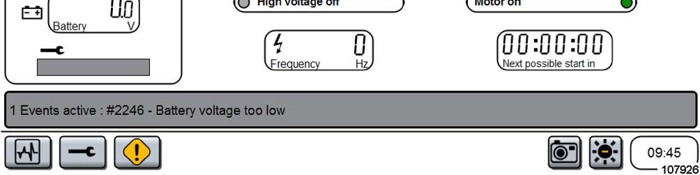
Information given on the start screen, lower section
1 Button “System Status”.
Tapping with your fingertip opens a gate to much more information about the shovels current behavior.
A menu will appear where you can select the section you want information about (see chapter “System Status”).
2 Button “ Setup Level I ”.
Tapping with your fingertip opens a login window that permits access to the BCS section that is exclusively for service personnel.
A password is needed to get access.
3 Button “Signal table”. Tapping this button opens a list of failures stored in the failure memory. A detailed description can be found in the “Technical Handbook”, chapter 9.
4 The “failure row”.
Here the system displayes detailed information about the failure occurred and gives instructions about what to do.
5 Tapping the „screenshot“ button produces a photo of the screen displayed to save current data.
6 Tapping the button toggles the background colour of the screen from white to black or vice versa.
7 Clock. Can be adjusted in the “Setup Level I” section by service personnel.

Information given on the “System Status” screen
1 Tapping this section with the high voltage arrow opens a screen displaying current data coming from the electric motor (see “Electric motor data screen”).
Same result when tapping on button “Motor”.
2 Tapping on the photo of the hydraulic pumps opens a screen displaying current hydraulic data (see “Hydraulic data screen”).
Same result when tapping on button “Hydraulics”.
3 Tapping on the photo of the lubrication control opens a screen displaying current lubrication data (see “Lubrication data screen”).


Same result when tapping on button “Lubrication”.
4 Tapping on the photo of the control lever (joystick) opens a screen displaying control elements adjusting data (see “Controls adjustment data screen”).

Same result when tapping on button “Servosystem”.
5 Tapping on this button opens the “Signal Table” screen (see: “Signal Table screen”).
Electric motor data screen (Service – Motor)
This screen displays data of the electric motor.
1 This section of the screen displays current data for all three phases of the electric motors windings:
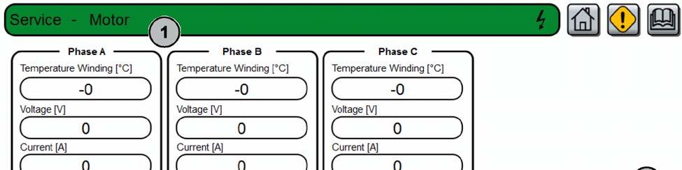
-Temperature in degrees Celsius,
-Voltage in Volts,
-Current in Amperes.
2 This section of the screen displays:
-Power factor,
-Frequency in Hertz,
-Total trip.
3 In this section information about the electric motors bearing temperatures are displayed.
Bearing (DE) °C =
Temperature of bearing on the Drive-End in degrees Celsius.
Bearing (NDE) °C =
Temperature of bearing on the Non-DriveEnd in degrees Celsius.
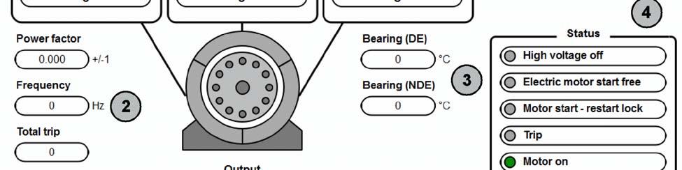
4 This section of the screen displays status information with red / green lights:
-High voltage off (red when off),
-Electric motor start free (green when free),
-Motor start – restart lock (red when locked),
-Trip (xxxxxxxx),
-Motor on (green when on),
-Temperature overload (red when overload),
- RTD alarm (red when……………),
- MPR internal error (red when………….),
-Phase ext. sequence fault (red when………).
5 This section of the screen displays the electric motors output data:
-Performance in kiloWatt (kW),
-Reactive in (kVAr),
-App. Pwr. IN (MWAh),
-Reactive pwr. (MVArh),
-Total consumption in (MWh),
-Apparent in (kVA), -App. pwr. out (MWAh).

Hydraulic data screen (Service –Hydraulics I)
1 This screen displays data related to the hydraulic system:
Servo control pressure, circuits 1 / 2 Pressure should be between 0 and 35 bars.
Main pump pressure at pumps no 1, 2, 3, 4.
Pump control pressure
Slew pump pressure at pumps 1,2, 3.
Slew charge pressure at pumps 1, 2, 3.
Slew circuit temp. = Hydraulic oil temperature in degrees Celsius in slew circuits 1, 2, 3.

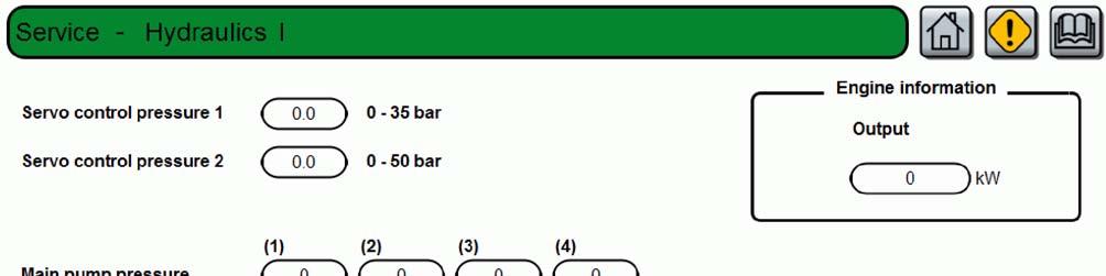
Further information on this screen: Electric motor output in kiloWatts (kW)
Hydraulic oil temperature(system) in degrees Celsius.

PTO Temperature = Oil temperature in pump distribution gearbox in degrees Celsius.
Environment = Ambient temperature in degrees Celsius.
Lubrication data screen (Service –Lubrication Lincoln)


Depending on the lubrication system build in the screen displayed may differ.
1 This screen displays data related to the central lubrication system. Here are information about the status of the lubricating system of the upper carriage.
2 If the system detects faults or malfunctions in the lubrication system of the upper carriage they are marked here with a red dot. Call the responsible service personnel. Malfunctions must be fixed as soon as possible. Serious damage of bearings and other parts of the equipment may occur when working without lubrication.
3 Here you get information about the status of the lubricating system of the under carriage (optional).
Controls adjustment data screen (Service – Servosystem)
The characteristic curves (ramps) of control levers (1, Fig. 13) and control pedals (2) are adjustable by service personnel. The adjusted values are shown here graphically and numerically.
The values set have influence on moving speed and smoothness of movements of the working equipment.
If adjustment is needed, call the responsible service personnel.
Adjustment is to be done in the “Setup” section of BCS IV. Access to this area is for service personnel only (password required).
Key switches in control levers can be checked by tapping on the touch sensitive areas below the control lever graphic. The colour changes from red to green.
1 Tapping on a joystick symbol displayes the current settings of the left / right control lever (colour changes to blue). Function of the key switches in the control lever are displayed as well.
2 Tapping on a pedal symbol displayes the current settings of the pedal (colour changes to blue).


3 Tapping the button “Slew brake test” opens the “Slew brake test” data screen.
4 Tapping the button “More details” opens a screen with current values set in the “Service - Servosystem” (see next page).

More details data screen (Service –Servosystem)
1 This area of the screen displays all currently set values for the lefthand control lever.

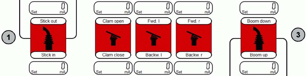

2 This area of the screen displays all currently set values for the pedals.
3 This area of the screen displays all currently set values for the righthand control lever.
Slew brake test data screen
A slew brake test must be performed during commissioning of the machine and after repair work or maintainance work carried out on the slewing system.
The slew brake test should be performed at every maintenance scheduled by the customer. This is to ensure proper functioning of the slew brake system. Proper functioning of the slew brake system has influence to machine safety.
Before performing the slew brake test, ensure the machine is in a safe workplace where the machine can rotate 360° without hitting an obstacle. Check that all persons have left the area around the machine. Activate the horn.
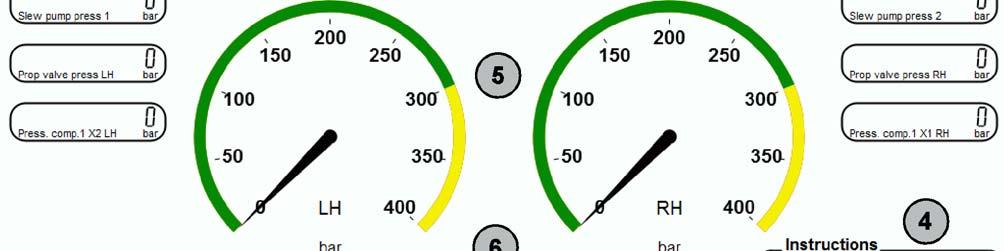
To perform the slew brake test, follow the instrucions (4) given on the screen.

1 Preconditions to be fulfilled before performing the slew brake test, from left to right: -swing brake applied, -servo control switch in control column must be in position OFF, -operator sitting on his seat
- symbol appear, with precondition fulfilled.

Time limit to fulfill preconditions is 60 sec.
2 Button to start the test.
3 Hydraulic pressures in the units of the slewing systems, lefthand and righthand.
4 Instructions to perform the slew brake test.
5 Instruments displaying hydraulic pressure in lefthand / righthand slewing system.
6 Indicators showing the progress during testing:
-“pending”, colour red after starting the test,
-“progress”, colour yellow when 300 bar, -“passed”, colour green when test OK.
Help / view documents screen

Technical documentation for the machine is stored on the mass storage device of the BCS. Tapping on the buttons opens the appropriate ADOBE® - PDF® file and displays it on the screen by means of the build in viewer. You can navigate inside the documents using the navigation elements known from other computer usage, like buttons, sliders, links from the contents page and so on.
1 Tapping the button “Software versions” opens a screen where the version numbers of all software programs installed on this system are displayed. See next page: “Software versions screen”.


Software versions screen

On this screen you find:
the serial numbers of hardware units (monitor, drive controller, servo controller and auxiliary controller).
the version numbers of software installed in the units (monitor, drive controller, servo controller and auxiliary controller).
(CMDI, i.e. “Caterpillar Mining Data Interface” is an option, not installed on this machine ex works).
These information may become relevant when ordering spare parts controllers or updating software.


Signal table screen
This is a listing of all the signal sources that are connected to the BCS- and eCAMP-system.
In the “Status” column small icons visualize the signal status: green=ok; red=malfunction. In case of malfunction inform the responsible service personnel immediately.
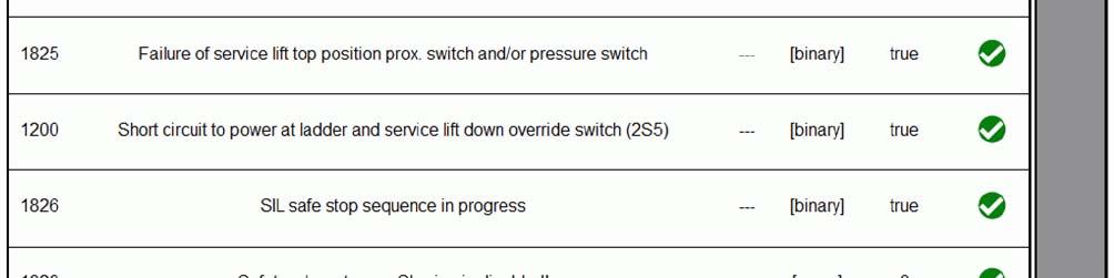
In column “Code” you can find the identifier for the sensor or unit that helps the maintenance personnel to localize the sensor in the electric schematics.

The slider (blue colour) on the right as well as the up and down arrows are to scroll a longer listing up and down.
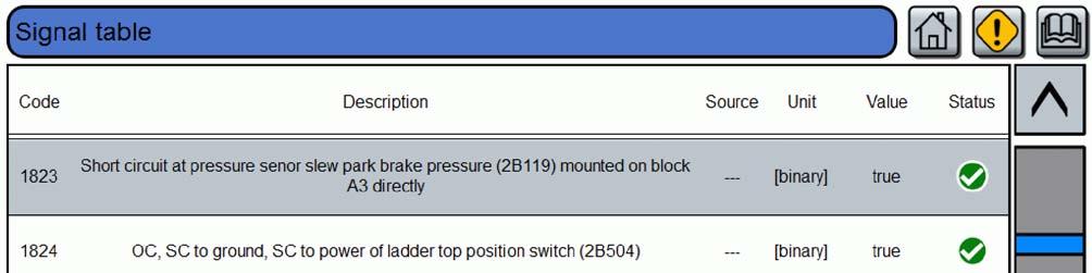
BCS IV, interfaces
The BCS system comes with different data interfaces. This feature allows the communication with external electronic devices.
Three connectors are located on the right-hand side-wall of the control column (Fig. 19):
1 USB 2.0, jack type A.
This jack accepts, for example, a USB stick used to save operating data for evaluation on an external computer.
2 Jack D sub, 9 pins.
Used to connect a computer with a diagnosis software with access to the CAN bus. This connection is reserved for service personnel.
3 Ethernet, jack type RJ45.
For the connection of future extensions, for example, the CMDI system (i.e. the Caterpillar Mining Data Interface).
USB interface, data storage
A USB stick can be connected to the USB plug-in connection of type A (1, Fig. 19).
Suitable are such USB sticks that would also work on computers with WINDOWS® operating systems; they may be formatted with the NTFS or the FAT32 file system.
If a screen page displays the button with the camera graphic symbol, the data visible on this screen page can be saved as a graphics file.
For a detailed description see section: “Saving data as a screenshot”.
Saving data as a screenshot
All screens which have the button with the camera graphic symbol (1, Fig. 20), offer the functionality to store data for external use.
The system creates a screenshot of the current visible screen. It will be stored as a graphics file on the mass storage device drive selected. Mass storage devices can be CF-memory cards (Compact Flash) or USB sticks.
In this example all data from the “Signal table” screen will be saved to a file. Fileformat is PNG (Portable Networks Graphic).
The file name will be automatically created following this pattern: “scr_date_number.png”.
Save data:
To create a screenshot, tap on button (1, Fig. 20). The BCS system checks the system for available mass storage devices (drives) and displayes them in a selection box (arrow, Fig. 20).

Select the drive you want to store the screenshot by tapping on the respective button. The screenshot is then automatically stored.
BCS IV, cleaning
Clean dirty screens with a soft, slightly moist cloth. In order to remove persistent dirt, you can use in addition a conventional cleaning agent for LCD monitors.
Never use solving or scouring cleaning agents.
This could damage the surface of the screen.
Do not use compressed air or water under pressure (high pressure cleaner or steam cleaner). This could damage the electronic components.
BCS IV, disposal
This electronic device contains substances that might be harmful to the environment.
The electronic components and the tubes of the background illumination contain, for example, lead (Pb) and mercury (Hg).
The background illumination lamps are CCFL-typelamps (Cold Cathode Fluorescent Lamps).
The battery for backing up the memory contains lithium.
Therefore, this device must not be disposed of with your regular household waste. It must be disposed of properly as electronic scrap.
The escaping liquid from a damaged LCD screen may be harmful. Do not come in contact with escaping liquids. In case of skin contact, wash immediately with water and soap.
TROUBLESHOOTING Instructions on troubleshooting
Faults are often due to the machine not being correctly operated or serviced.
For this reason, it is vital to read through the relevant section of the Operation and Maintenance Manual once again before rectifying any faults. If you are unable to detect the cause of the fault or to rectify it, apply to the CGM-HMS GmbH aftersales service.
Describe the fault and all accompanying circumstances as precisely as possible when calling on the CGM-HMS GmbH after-sales service. Exact data allow for fast troubleshooting.
Never do any jobs for which you are not qualified. The fault table lists all faults which have been reported to date and outlines their possible causes and rectifying measures. In exceptional cases, a described fault may also have a different cause.
Layout of the fault table Fault
The fault is described here as the outcome of an observation or a previous activity. Therefore make careful observations. Study the problem carefully. First think, then act. Ask yourself the following questions:
Which warning signals preceded the fault?
What repair and servicing work was carried out previously?
Has this defect already occurred?
Is it one or several simultaneously occurring faults?
Possible causes
The possible causes of the observed fault are outlined in this group. They are arranged in order of probability, i.e. the possible cause occurring in most cases heads the list.
Measures
This describes the troubleshooting procedure.
Section
This specifies where information on troubleshooting is given in the Operation and Maintenance Manual. If there is no entry, the CGM-HMS GmbH after-sales service should be consulted
Fault Tables
Working hydraulics – Fault table
Track drive – Fault table
temperatur too high (warning lamp lit, PMS fault cator lamp lit) oil cooler contaminated
Swing mechnism – Fault table
Central lubricating system – Fault table
not working, the BCS does not indicate a warning
Hydraulic Circuit Diagram
Detailled information can be found in the „Service Manual“ chapter 8 or contact CGM-HMS GmbH service
Abbreviations
A Ampere (SI base unit of electric current) abt. about acc. according to Ah Ampere hours (SI base unit of quantity of electricity)
API American Petroleum Institute approx. approximately
BA = OMM = Operation and Maintenance
Manual bar unit of pressure, 1 bar = 14.5 psi
Bh = OH = Operating hour
CE Communauté Européenne = European community
CECE Committee for european Construction Equipment (Defines a measure for bucket, grab or scoop filling)
CEN European Standardization Committee cm centimeter (= 1/100 m) cm3/rev Cubic centimeters per revolution
CCW counterclockwise
CW clockwise dB(A) Decibel (sound intensity according to measuring method A) dia. Diameter
DIN German Industrial Standard
EDS Electronic diagnostic system eff. effective e.g. for example etc. etcetera
Fig. Figure, serial number of illustration
FOPS Falling objects protective structures
FS Rock shovel (working equipment) ft foot (unit of distance), 1 ft = 0.30 meter gal gallon (unit of volume), 1 gal = 3.78 liters
GLR Full-load controller (electronic module for PMS)
HD Heavy duty
Hydr. Hydraulic, Hydraulics i Transmission ratio i.e.id est = that is
IFN ISO service rating, blocked
Incl. including, inclusive of ISO International Standardization Organization kg Kilogram (unit of weight), 1 kg = 2.2 lb kg/dm3 Kilograms per cubic decimeter (= unit of specific density) km/h Kilometers per hour kNm
KiloNewtons per meter (1 kNm = 1000 Nm) = unit of torque kW Kilowatt (1 kW = 1.36 hp) l Liter (unit of volume), 1 liter = 0.26 gal lb pound (unit of mass), 1 lb = 0.45 kg
Lb/in² Pounds per square inch (= psi)
LC Long crawler
LDA Charge pressure-dependent full-load limiter
LED Light-emitting diode l/min Liters per minute
LpA Sound pressure at workplace
LS Limited slip
LwA Sound power level of the machine in stationary operation m Meter (unit of distance), 1 m = 3.28 ft
MA Tightening torque mA Milliampere (=1/1000 A) max. maximal, maximum min. minimal, minimum min-1 Revolutions per minute mm Millimeter (=1/1000 m)
N Normal, standard version
N, kN Newton, kiloNewton (unit of force)
NLGI National Lubricating Grease Institute (USA)
NLGI-Klasse Consistency - lubricant classification acc. to DIN 51 818
Nm Newtonmeter (unit of torque)
No. Number
OH Operating hour op.inst. Operating instructions
OW Superstructure oz ounce (unit of volume) 1 oz = 0.03 liter
Abbreviations
PMS Pump Managing System
P/No. Part number (CGM-HMS GmbH )
PS Metric horsepower (1 PS = 0.74 kW) psi pund per sqare inch (unit of pressure), 1 psi = 0.069 bar
PLC Programmable logic controller
Qty. Quantity
R, r Radius resp. Respectively
RH Crawler hydraulics (hydraulic shovel)
ROPS Roll-over protective structures rpm Revolutions per minute (= min-1)
SAE Society of Aotomotive Engineers (USA) sec./s. Second
SN CGM-HMS GmbH partnumber
SW Width across flats t Metric ton (= 1000 kg)
TBG Civil Engineering Employer's Liability Insurance Association
THB Service Manual
TL Backhoe dipper (attachment) tm Tons by meters (obsolescent unit of swing torque) typ. Typical
U/min Revolutions per minute
UW Undercarriage
V Volt (unit of electric voltage)
VDMA Association of German Machinery and Systems Manufacturers
W Watt (unit of electric power)
°C Degrees Celsius (temperature)
°F Degrees Fahrenheit (temperature)
> greater than
< less than
Noise And Vibration Information
Noise emission information
Noise emission data are specified in acc. with ISO 6394.
Time-averaged A-weighted emission sound pressure level at operator’s position with the machine running at high idle: LAeq = XX dB.
Vibration information
On the condition that the hydraulic shovel is used within the limits of its designated use, the installation of seats for operators in conformity with ISO 7096 ensures that the weighted vibration accelerations awz (measured in compliance with ISO 2631 Part I) fulfil the requirements with respect to the protection against whole-body vibrations in acc. with EC Vibration Directive 2002/44/EG.
The vibrations operatored are indicated in acc. with EC Machine Directive 2006/42/EG, Annex I; Section 3.6.3.1, resp. with the "Regulations for noise and vibration at the place of work", Section 4, as of 18.12.2008.
The effective value of the weighted acceleration to which the wole body is exposed, does not exceed 0.5 m/s2
The measurement uncertainty is ±3% (tolerance of the measuring instruments).