
24 minute read
Active-power transducer - Function


The electrical system of this machine is equipped with an active-power transducer. The transducer is located in the 400 V switch cabinet (arrow, Fig. 2-94:).
The active-power transducer measures permanently the currents, voltages and phase angles in the system and derives the active power (P) the apparent power (S) and the reactive power (Q) from these values. All these measured values can be displayed on the screen
The active-power value is used to generate an analog signal (4-20 mA). This signal is used to monitor the tilting angle of the hydraulic pumps. In combination with the Pump Management System (PMS), any overloading of the electric motor due to an excessive demand of hydraulic power is thus avoided.
The device is factory-programmed in such a way that all relevant measured values can be displayed in four screens on the monitor (1, Fig. 2-95:). The different screens are selected with the keys (3).
Screen 1 displays the numeric values of:
the voltages of phases L1, L2 and L3 and the total current.
Screen 2 displays the numeric values of:
the active-power (P), the apparent power (S), the reactive power (Q) and the frequency.
Screen 3 displays a current / voltage diagram. Screen 4 displays the numeric values of:
the currents of phases L1, L2 and L3
For more information please refer to the the manufacturer's description.
1 Display screen for measured values and menus.
2 ENTER key, switches display illumination on / off; confirms item selection in menus
3 Keys for display navigation; selects the screens for measured values and menus.
Warm-up procedure for electric driven shovel
Operator procedure during start up in extreme cold weather
After starting the electric motor check for any faults on the BCS display.
Make sure the “Servo” switch (74, Fig. 2-103:) is in the OFF position.
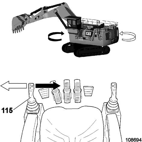
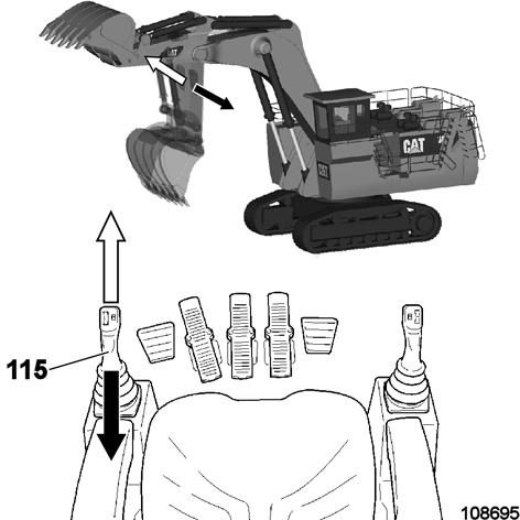
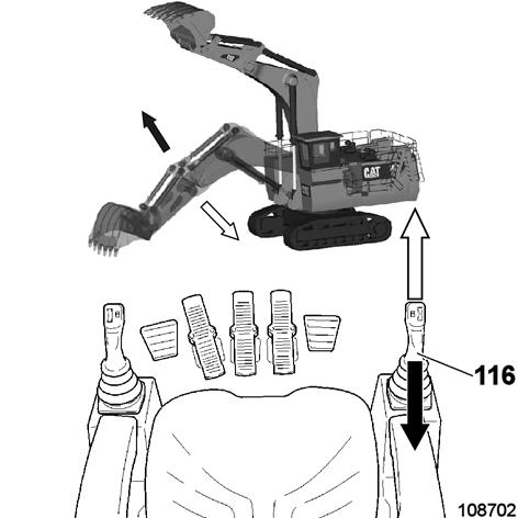
Use the “Boom up” (116, Fig. 2-104: backwards) or “Stick out” function (115, Fig. 2-104: forwards) to engage the hydraulic pumps. This will engage the pumps without moving the attachment.
Do so until:
- the hydraulic oil temperature reaches 10°C / 50°F on the gauge and
- the PTO temperature has reached 5°C / 41°F.
You can now turn ON the “Servo” switch (74) and move the attachment in a slow function one at a time.
Do not extend the cylinders fully.
Swing circuit warm-up before you start digging
Make sure the attachment or bucket is on the ground.
Turn “Swing brake” switch OFF (82, Fig. 2-103:).
Turn “Servo” switch ON (74, Fig. 2-103:).
Use “Swing left” or “Swing right” function (115, Fig. 2-105:) slowly. This will heat the swing hydraulic circuit quickly.
Once the swing temperature is warm you can lift the attachment and swing the excavator in a slow 360° left then right.
When working constantly at low outside temperatures activate the “Cold area warm-up mode” of the BCS (At machines with CAMP/SIL electric system). Refer to Operation and Maintenance Manual, section “Cold area warm-up mode – activate”.
Preheating system for hydraulic oil reservoir and pump gearbox, switching on and off
Preheating systems are build in at the hydraulic oil reservoir as well as in the pump gearbox. On low outside temperatures they warm up the hydraulic oil as well as the gear oil so that the operating temperature is reached faster.
Integrated thermostats prevent the heating elements from overheating and damage at continious operation.
The heating elements are connected electrically to a centralized switchbox. The switchbox is fixed at the hydraulic oil reservoir and can be accessed from the pump- or motor compartment (Fig. 2-99:). After the power supply for the excavator is switched on the preheating system is functional. (The circuit breaker must be switched on, the indicator lamps "7.2kV OK" and "PHASE SEQUENCE OK" are on at the control cabinet 400V).
Switch on the preheating system before starting work using switches at the switchbox (Fig. 2-99:).
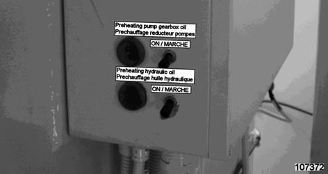
The monitoring lamps near the switches lit up then.

Air conditioner (optional) Ventilation / Heating
The air needed for ventilation and/or heating is sucked in from outside the cab by a blower and ducted to the air outlets.
If necessary, the air in the cab is sucked in through the air conditioner and recirculated.
The air conditioner control elements are located at the left side of the control column (Fig. 2-100:).
Do not switch the air conditioner to "cooling“ when the back-up heating (optional) is on.
Back-up heating operator’s cab (optional)
The back-up heating for the operator’s cab is located in the module below the operator’ cab (Fig. 2-101:). The heating consists of one or two heating units (1) and the fuel reservoir (2).
Switch on the back-up heating using switch (142, Fig. 2-102:). The pilot lamp above switch (142)lights up.
The heating system has an automatic regulation.
Do not switch on the back-up heating when the air conditioner is set to ”cooling”.
Control panel (SIGMA)
(see Fig. 2-100:)
1 Rotary switch Selects the intensity level of the blower (3 levels).
2 Rotary switch Selects the desired control function (heating, cooling, ventilation, defrosting).
3 Thermostat Sets the desired temperature inside the cab.
Operational Practices
Working operation - Safety instructions
Personnel
Any work with the machine must be executed only by reliable, skilled and well trained personnel in good healthy condition. Statutory minimum age limits must be observed.
Never operate the machine while impared with drugs or alcohol.
Read the sections "Fundamental safety instructions" and "Operation, safety instructions" in this Operation and Maintenance Manual carefully and observe the instructions given in this sections.
Observe all job site safety requirements.
State of the site
Inspect the site for underground gas, power and water lines before starting work. Any damage to such lines is a risk to life!
Clear all obstacles from the path of the machine. Sound the horn to warn persons in the immediate vicinity before starting work.
Stop work if anyone is in the hazard range of the machine. Make sure all persons have left the hazard range before resuming work.
Machine stability
Never operate the machine unless it is standing on a reasonably horizontal, flat surface. The stability of the machine is otherwise at risk.
When working or traveling on a slope is required, do not exceed the maximum machine inclination for working operation and for traveling (refer to Operation and Maintenance Manual section “Maximum machine inclinations”).
Ensure that the attachment has adequate clearance below overhead power lines and structures. Trenches and working faces may give way. Keep well clear of them.
As travel brakes are deactivated, the machine could slightly move in direction of excavating during operation. Whenever loading operation is interrupted, stand attachment on the ground. This avoids slight movement of the machine and possible consequential damage of lowered ladder, in case ignition remains engaged.
State of operator’s workplace
Inspect and fasten your seat belts.
Adjust the operator’s seat for comfortable reach all controls and pedals. Adjust for operator height and weight.
Keep your workplace clean. Remove all unsecured items like tools and other supplies from the cab. Clean off any earth, mud, snow, ice, grease and oil adhering to your working footwear before operating the machine. There is otherwise a risk of slipping off the pedals and initiating inadvertent movements.
Clean and secure all windows and doors.
Clean and adjust all mirrors for optimum vision. Start the electric motor only from the operator’s compartment.
Operate the machine only while sitting on the operator’s seat.
State of the machine
Operate the machine only if all protective and safety oriented devices, such as removable safety devices, emergency shut-off equipment, soundproofing elements and exhausters, are in place and fully functional.
Do not operate the machine,
when several track rollers or upper rollers have been removed;
when one or several swing gearboxes have failed or been removed;
when one or several teeth on the backhoe or on the shovel are worn or missing;
when parts of the hardfacing layer on the backhoe or on the shovel are worn or missing.
when sun shades are unlocked.
Working under these circumstances results in heavy wear and possibly in severe damage and thus in high repair costs.
Such circumstances are considered by CGM HMS as "abusive utilization".
CGM HMS refuses to assume the guarantee for damage and consequential damage caused by an abusive utilization of the machine.
Trailing cable
Never touch the trailing cable. Risk of voltage drive, if the trailing cable insulation is defective!
Change the position of the trailing cable only by means of a cable hook.
Before starting work
Perform a machine walk around inspection. Report any obvious damage and defects – including changes in the machine’s working behaviour- to your supervisor. In the event of malfunctions, stop the machine immediately and lock it.
Lock sun shades on the right and left side of the cab. Opened and unlocked sun shades can be damaged by the working equipment in motion or even damage the operator's cab.
Prior to initial commissioning and after repairs on the central lubricating system or the hydraulic cylinders, move the unloaded equipment for abt. 5 minutes. This is required to ensure an adequate supply of grease to the cylinder bearings when the work starts.
Prior to each shift perform a complete 360° swing movement of the upper structure. Doing this ensures proper distribution of grease and brings all the bearing rollers inside the swing ring to new positions.
Machine Operating Temperature Range
The machine must function satisfactorily in the anticipated ambient temperature limits that are encountered during operation. The standard machine configuration is intended for use within an ambient temperature range of 20 °C (-4 °F) to 55 °C (131 °F). Special configurations for different ambient temperatures may be available. For use at temperatures below -10 ° C (14 ° F), the machine can be equipped with a cold weather package. Consult your Caterpillar dealer for additional information on special configurations of your machine.
Warm-up procedure for electric driven shovel
Operator procedure during start up in extreme cold weather
After starting the electric motor check for any faults on the BCS display.
Make sure the “Servo” switch (74, Fig. 2-103:) is in the OFF position.
Use the “Boom up” (116, Fig. 2-104: backwards) or “Stick out” function (115, Fig. 2-104: forwards) to engage the hydraulic pumps. This will engage the pumps without moving the attachment.
Do so until:
- the hydraulic oil temperature reaches 10°C / 50°F on the gauge and
- the PTO temperature has reached 5°C / 41°F.
You can now turn ON the “Servo” switch (74) and move the attachment in a slow function one at a time.
Do not extend the cylinders fully.
Swing circuit warm-up before you start digging
Make sure the attachment or bucket is on the ground.
Turn “Swing brake” switch OFF (82, Fig. 2-103:).
Turn “Servo” switch ON (74, Fig. 2-103:).
Use “Swing left” or “Swing right” function (115, Fig. 2-105:) slowly. This will heat the swing hydraulic circuit quickly.
Once the swing temperature is warm you can lift the attachment and swing the excavator in a slow 360° left then right.
When working constantly at low outside temperatures activate the “Cold area warm-up mode” of the BCS (At machines with CAMP/SIL electric system). Refer to Operation and Maintenance Manual, section “Cold area warm-up mode – activate”.
Electronic hydraulic shovel control (pilot control) – activate
The hydraulic shovel can execute working movements only after the electronic hydraulic shovel control (pilot control) has been activated. The pilot control block is enabled by switch (71, Fig. 2-106:).
At the beginning of the work, the electronic hydraulic shovel control (pilot control) is activated by a contact in the operator's seat (105):
Electronic hydraulic shovel control ONThe operator is sitting on his seat.
Elektronic hydraulic shovel control is OFFThe operator's seat is empty.
Note:
During operation it is absolutely necessary that the operator keeps sitting on his seat. Otherwise working movements may be interrupted suddenly. Risk of damaging the holding brakes and the gearboxes.
Working operation – basics
This section gives you basic information about the functions of the joystick controls. For further detailed information refer to section “Operation Techniques” in this Operation and Maintenance Manual:
“Machine operation with backhoe attachmentBest Practices”,
“Machine operation with backhoe attachment –Restricted Operation”,
“Machine operation with face shovel attachment - Best Practices”,
“Machine operation with face shovel attachment – Restricted Operation”.
Working on level ground
CGM HMS recommends operating the machine on level and stable ground. Doing so ensures maximum productivity and prevents machine components from premature wear.
Working on slopes or on rough terrain
Clean and level rough terrain before moving into the bank. A clean, level pit floor is necessary for safe and stable machine operation and prevents the tracks and other components of the undercarriage from being damaged.
When working or traveling on a slope is required, do not exceed the maximum machine inclination for working operation and for traveling (refer to Operation and Maintenance Manual section “Maximum machine inclinations”).
If the machine begins to sideslip on a slope, immediately lower the attachment and the load to the ground and turn the machine facing downhill.
Operate the machine slowly, accelerate and decelerate attachment movements gently. Sudden movements with full speed and filled bucket are a huge strain for the structure which could tip the machine over.
When working on a slope, always operate the hydraulic shovel with the attachment positioned uphill or downhill, never sideways.
When traveling up and down a slope or when traveling over rough terrain reduce travel speed mode to slow (refer to Operation and Maintenance Manual section “Traveling”).
Operate joystick controls gently
Accelerate and decelerate attachment movements gently. Sudden acceleration and abrupt braking with full speed and filled bucket are a huge strain for the structure.
Avoid aggressive operating practices. Do not overload the machine.
Upper structure – swing
Swinging of the upper structure is possible only when:
the upper structure holding brake is released and
the hydraulic shovel operator is sitting on his seat and
the hydraulic ladder is raised and
the servicestation (tanklift) is raised and
the BCS swing circuit test was successful.
To swing the upper structure to the rightmove the left joystick to the right (115, Fig. 2-107: and Fig. 2-108:).
To swing the upper structure to the leftmove the left joystick to the left (115).
After releasing, the joystick returns automatically to position "0".
Note: Releasing the joystick (115) is not sufficient to brake the swinging upper structure automatically. In order to brake the upper structure, the joystick must be moved in the direction opposite the swinging movement (reversing).
Upper structure – brake
The upper structure can only be braked by moving the joystick (115) in the direction opposite the swinging movement (reversing).
The sw inging upper structure does not stop automatically by simply releasing the left joystick (115).
To brake the upper structure, the left joystick (115)must be moved in opposite direction. In an emergency, push the Emergency-Stop button (35, Fig. 2-108:) or activate the holding brake by pressing switch (61, Fig. 2-108:).
Stick in / Stick out control
When released, all joysticks for working operation return automatically to position "0".
To extend the stick (Stick out): push joystick (115, Fig. 2-109:) forwards.
To retract the stick (Stick in): pull joystick (115) backwards.
To retract the stick with pressure: depress button (102, Fig. 2-110:) and push joystick (115) backwards. Note: This function works on face shovel attachment only, here the stick-in-function is normally done by gravity.
Raising and lowering the boom
When released, all joysticks for working operation return automatically to position "0".
To raise the boom: pull joystick (116, Fig. 2-111:) backwards.
To lower the boom: push joystick (116) forwards
To lower the boom with pressure: depress button (103; Fig. 2-112:) and push joystick (116) forwards Note: This function works on face shovel attachment as well as on backhoe attachment. The boom-down-function is normally done by gravity.
Filling and emptying the backhoe bucket
When released, all joysticks for working operation return automatically to position "0".
To fill / tip back the backhoe bucket: shift joystick (116, Fig. 2-113:) to the left.


To empty the backhoe bucket by dumping / tipping: shift joystick (116) to the right.
Filling the face shovel, curl close / curl open
When released, all joysticks for working operation return automatically to position "0".
To fill / curl close the face shovel: shift joystick (116, Fig. 2-114:) to the left.
To curl open the face shovel: shift joystick (116) to the right.
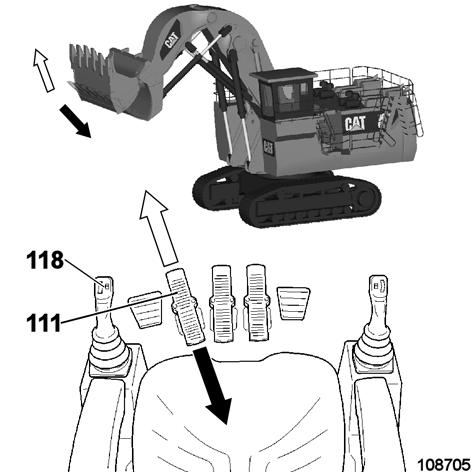
Opening and closing the face shovel clam
When released, all joysticks for working operation return automatically to position "0".
To open the face shovel clam: press pedal (111, Fig. 2-115: and Fig. 2-116:) forwards or turn thumb wheel (118) forwards.
To close the face shovel clam: press pedal (111) backwards or turn thumb wheel (118) backwards. Note: Pressing pedal (111) overrides turning the thumb wheel (118).
Operation Techniques
Machine operation with backhoe attachment, Best Practices
Machine Stability
The hydraulic shovel must always be operated in a way, that its stability is always ensured and the danger of tipping over is avoided.
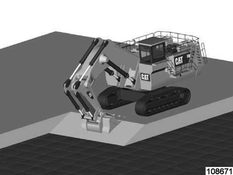
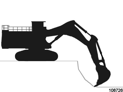
Machine stability is greater when the bucket is parallel with the tracks (Fig. 2-117:).
When working with the bucket parallel to the tracks, the final drives should be in the rear position, for the following reasons:
The travel motors and final drives are protected from falling rocks etc.
When the hydraulic shovel is operated on muddy ground and the tracks are covered with mud, the sprocket runs on a clean track when backing up.
When working with the attachment in a cross direction to the tracks, be sure that the track is not raised off the ground. This can cause the track to set-off from the rollers when it is lowered down on the ground.
Also the flanges of the track rollers and the track shoes can be bent by the excessive load.
Refer to Operation and Maintenance Manual, “Restricted Operation” for further detailed information.
Do not overfill / overload the bucket, the machine may tip over.
When working or traveling on a slope is required (Fig. 2-118:), do not exceed the maximum machine inclination for working operation and for traveling (refer to Operation and Maintenance Manual section “Maximum machine inclinations”).
Do not operate the shovel on rain-slicked, slippery slopes. The shovel may slip.
Clean and level the pit floor before moving into the bank. A clean, level pit floor is necessary for safe and stable machine operation and prevents the tracks and other components of the undercarriage from being damaged.
Position the hydraulic shovel on level, consistent, firm and stable ground.
The hydraulic shovel may gradually sink on soft and yielding ground. Always re-enforce soft and yielding ground with firm material.
If it is unavoidable to work on soft and yielding ground, operate the machine at reduced bucket loads to avoid tipping of the machine.
When working on high-density and coarse material, operate the machine at reduced bucket loads to avoid overloading and damaging components of the machine.
Stand attachment down to the ground during breaks in working operation.
Do not operate the hydraulic shovel in water or in mud deeper than the breather valves of the final drives. Refer to section “Restricted Operation”.
Know the situation on site
To maximize productivity of the machine, it is important that the operator understand characteristics of the material they are digging and how to adjust their operating style accordingly.
Material penetrability:
Easily penetrable material: All loose, free flowing material and all materials which can be excavated without blasting.
Difficult to penetrate material: Blasted or unblasted material containing large chunks, wet clayey soil and overburden.
Material flow:
Free flowing / loose.
Sticky / in situ.
Conditions favorable to hydraulic backhoes: (Preferred option for overburden and softer material)
Low to moderate bench heights (Refer to section “Bench Heights – Recommendations for BH-machines”)
Truck spotted either on top of bench or on the floor below the backhoe
Tight load area
Short swing – 60°
Well-shot material
Conditions unfavorable to hydraulic backhoes:
High benches
Excessive tramming
Multiple benches
Unstable benches
Low angle of repose
No cleanup support
Bench - Climbing and Leaving
Climbing Onto a Bench
Operation
Do not exceed the maximum machine inclination or working. Refer to Operation and Maintenance Manual section “Maximum machine inclinations”. Build the ramp.
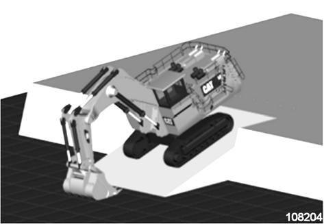
Travel up the ramp onto a bench with idlers first, keep the bucket close to the ground.
If necessary, engage the bucket into the ground and move working equipment towards the machine. This procedure supports the machine while climbing the steep ramp (Fig. 2-119:).
Build the ramp. If the bench is steep, bring the hydraulic shovel down the bench with the final drive first.
Keep the bucket close to the ground (Fig. 2-120:).
Bench Heights – Recommendations for BH-machines
Insufficient bench height
A too low bench does not allow good bucket fills and involves the risk to pull material against the tracks (Fig. 2-121:).
Insufficient height increases the danger of collision between excavator and truck under certain circumstances (Fig. 2-121: and Fig. 2-122:).

A sufficient bench height is essential for efficient and safe operation.
The ideal bench height is equal to the stick length or equal to the truck body rail height (Fig. 2-123:). Note: This is a rule of thumb and is valid only if the material allows this bench height and only for standard truck match.
For more information please refer to section “Bench Heights – Recommendations for BHmachines, table”.
Loading setups
The following setups are used for digging and loading with the hydraulic shovel:
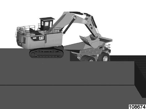
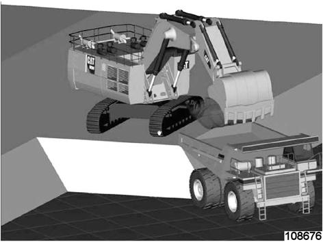
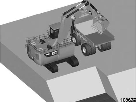
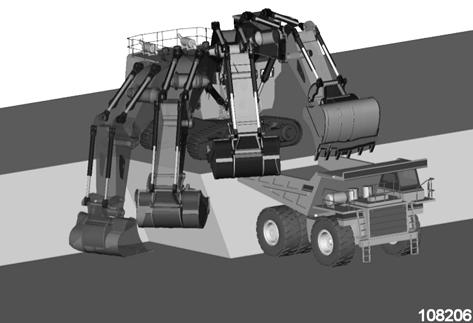
Hydraulic shovel on top of the bench, and truck below (This is the typical application).
Hydraulic shovel and truck on the same level.
Working with the hydraulic shovel on a proper bench height and the truck below (Fig. 2-124: and Fig. 2-125: and Fig. 2-126:) offers the following improvements:
15-20% more production.
Clear separation of loading and hauling equipment.
Less risk of collision.
Excellent operator view into the truck body.
Potential for short swing angles.
Shortest attachment lifting distance possible.
Various options for truck positioning with loading through the body gate or over the side wall.
Productivity increases:
10 – 15% higher productivity when bench is correct height vs. too high or to low.
15 – 20% higher productivity when trucks are spotted on the floor below the excavator vs. on top of bench.
5% higher productivity when excavator swings 60º vs. 90º.
Higher productivity when positioned as close to edge as safely possible.

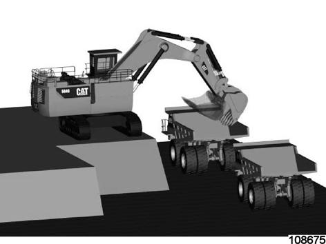
Truck on lower level — drive-by loading (Fig. 2-127:):
Advantage:
Truck spotting time is eliminated, for the highest productivity, because the next truck does not need to reverse for positioning
Disadvantages:
More than 90° swing angle.
Loading through the gate could be more difficult due to limited space for dumping.
Truck on upper level — top loading (Fig. 2-128:):
Working with the hydraulic shovel and the truck on the same level offers the following improvements:
Loading over side walls offers reduced swing angle.
Loading over tail offers reduced lifting effort for faster cycles.
This working technique is best applied for drop cuts and in difficult to access or wet areas at the pit bottom.
Disadvantages:
Increased lifting effort and larger swing angle requires longer cycle time.
Productivity is approximately 15 to 20% lower.
Bench Heights – Recommendations for BH-machines, table
Digging and Loading
Loading Trucks, do:
Start at "key cut" and work toward the truck.
Always work over the idler and swing no more than 60° to the truck.
Prepare the next cuts in advance.
General digging advance is backwards.
Maintain a proper bench height.
Position the truck close enough to the machine for effective loading, but not too close so that the machine cannot hit and damage the truck.
Most productive work is performed with the truck on a lower level.
Swing the attachment at a sufficient height over the loading platform.
Distribute material evenly on the truck bed.
Remove sticky material from the bucket.
Always keep the shovel as close as possible to the work area. This minimizes short stick and boom movements - high efficiency.
Correct bucket size and properly adjusted equipment prevents overloading and ensures maximum operating efficiency of the hydraulic shovel.
Loading Trucks, do not:
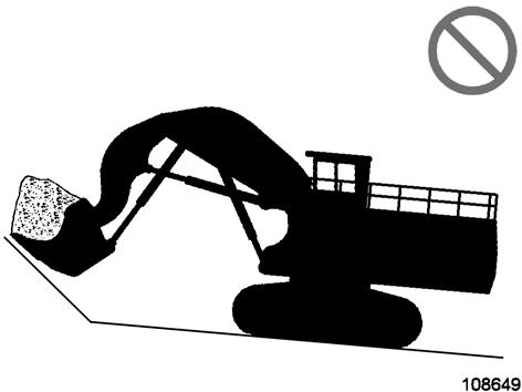
Do not swing the attachment over unprotected driver cabs.
Do not overload the truck.
When turning into a pit, the swing motion must not be stopped by the walls of the pit. Doing so can cause structural damage to the attachment.
Use the machine hydraulic system to stop the swing motion.
Only a bucket with a complete set of teeth and cutting edges in good condition ensures efficient performance.
Loosen hard material and rocks with the bucket, not with the stick crowding thrust.
Avoid digging with corner tooth to avoid torsional forces into attachments.
Avoid contacting mechanical stops and cylinders end of stroke.
Refer to Operation and Maintenance Manual chapter “Backhoe Operation - Restricted Operation” for further details.
Digging and loading a truck
Use the following guidelines when digging and loading a truck (Fig. 2-129: and Fig. 2-130:):
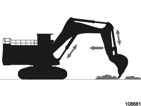
Position the stick at an angle to the ground as shown in (Fig. 2-130:).
Position the bucket cutting edge at an angle to the ground as shown in (Fig. 2-130:). This allows maximum breakout force to be exerted throughout the dig cycle.
Move the stick towards the cab and keep the bucket parallel to the ground.
If the stick stops due to the load, raise the boom and / or perform a curl in order to adjust the depth of the cut.
To apply the greatest force at the cutting edge, decrease the down pressure as you move the stick toward the cab.
Maintain a bucket attitude that ensures a continuous flow of material into the bucket.
Continue the pass in a horizontal direction so that material peels into the bucket.
Curl in the bucket and raise the boom when the pass has been completed.
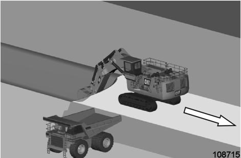
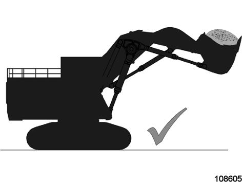
Swing the load from the rear of the truck or from the side of the truck. Never swing a load over a truck cab or personnel.
To dump a load, move the stick outward and open the bucket in a smooth motion.
Load trucks evenly. This will help to avoid overloading the rear axle.
When bucket is empty, swing the upper structure back and begin the next loading cycle.
Double Benching
Double Benching is an operation method which could be productive but also be very harmful to component life. This method should be used only by well trained and experienced operators in accordance with the following rules.
Rules for “Double Benching” Material:
Loose, well blasted and easy to dig material is absolutely essential for Double Benching.
Boom down function should be used in float position only to pull down material from the wall. Note: Digging poorly blasted material with great boulders or too tough material is a great stress for the steel structure and could result in serious damages.
Do not use the “Power boom down” - function. Always maintain a proper distance to the highwall to avoid operating at the limits of the cylinders.
Bench height:
A high bench is split up into two segments, 1/3 of the bench is below the excavator and 2/3 is above the excavator (Fig. 2-131:).
The ideal upper bench height is when the bucket could lay flat on the top of the bench (1, Fig. 2-131:).
The ideal lower bench height is equal to the length of the stick or equal to the truck body side wall edge.
Note: Too low lower benches can cause collisions of the counterweight and the truck body.
Working direction:
While digging the upper bench, the cab must be on the opposite side of the high wall, swing direction is to the truck / cabin side (Fig. 2-131:). Dig forward (arrow, Fig. 2-131:).
While digging the lower bench, the cab must be on the opposite side of the high wall, swing direction is to the truck / cabin side (Fig. 2-132:). Dig backwards (arrow, Fig. 2-132:).
Working method:
Dig the upper bench first, progressing from right to left, by digging down material from the face (Fig. 2-131:).
Dig the lower bench on the way back in standard setup from left to right (Fig. 2-132:).
Dig a trench in front of the machine and along the high wall (2, Fig. 2-131:).

Leave this trench along the dig face (approx. 1.5 meters / 5 ft. deep) while digging forward.
If any spillage falls out it is collected in the trench and won’t damage the excavator.
The hole in front of the machine also eases bucket fill.
Grading the pit floor
The described grading function can be performed precisely by simultaneously use of the boom, stick and bucket function.
Position the stick slightly forward of the vertical position with the bucket in the dumped position (Fig. 2-133:).
Operate the stick-retract function while slowly raising the boom. When the stick moves past the vertical position, slowly lower the boom to allow the bucket to maintain a smooth surface.
Park the Machine
Park the machine in a location that is smooth, stable, level and hard. The location should also be dry and free of debris and not endangered by falling rock. Bring the attachment in a position like shown in (Fig. 2-134:):
- Half extend the boom cylinders.
- Bring the stick in a vertical position.
- Lower the boom until the bucket is on the ground.
Note: Other positions of the attachment are not allowed when parking the machine. Refer to section “Backhoe Operation - Restricted Operation”.
Machine operation with face shovel attachment - Best Practices
Machine stability
The hydraulic shovel must always be operated in a way, that its stability is always ensured and the danger of tipping over is avoided. Machine stability is greater when the bucket is parallel with the tracks (Fig. 2-135:).
When working with the bucket parallel to the tracks, the final drives should be in the rear position, for the following reasons:
The travel motors and final drives are protected from falling rocks etc.
When the hydraulic shovel is operated on muddy ground and the tracks are covered with mud, the sprocket runs on a clean track when backing up.
When working with the attachment in a cross direction to the tracks, be sure that the track is not raised off the ground. This can cause the track to set-off from the rollers when it is lowered down on the ground.
Also the flanges of the track rollers and the track shoes can be bent by the excessive load.
Refer to Operation and Maintenance Manual, “Restricted Operation” for further detailed information.
Do not overfill / overload the face shovel, the machine may tip over.
When working or traveling on a slope is required (Fig. 2-136:), do not exceed the maximum machine inclination for working operation and for traveling (refer to Operation and Maintenance Manual section “Maximum machine inclinations”).
Do not operate the shovel on rain-slicked, slippery slopes. The shovel may slip.
Clean and level the pit floor before moving into the bank. A clean, level pit floor is necessary for safe and stable machine operation and prevents the tracks and other components of the undercarriage from being damaged.
Position the hydraulic shovel on level and firm ground. The hydraulic shovel may gradually sink on soft ground. Always re-enforce soft ground with firm material.
When working on soft ground or on high density material, operate the machine at reduced bucket loads.
Stand attachment down to the ground during breaks in working operation.
Do not operate the hydraulic shovel in water or in mud deeper than the breather valves of the final drives. Refer to section “Restricted Operation”.
Know the situation on site
To maximize productivity of the machine, it is important that the operator understand characteristics of the material they are digging and how to adjust their operating style accordingly.

On the site different bench height characteristics can exist:
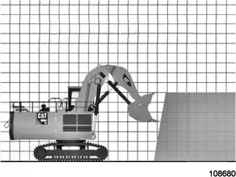
A steep slope with an angle > approx. 60° and sticky, in-situ material (Fig. 2-137:).
A flat slope with an angle ≤ approx. 60° and free flowing, loose, blasted material (Fig 2-138:).
Material penetrability:
Easily penetrable material: All loose, free flowing material and all materials which can be excavated without blasting.
Difficult to penetrate material: Blasted or unblasted material containing large chunks, wet clayey soil and overburden
Material flow:
Free flowing / loose.
Sticky / in situ.
Bench Heights on Steep Slopes
Minimum Bench Height
Hydraulic face shovels can work on low faces due to their kinematics.
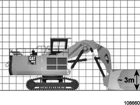
The working face should be at least as high as the bucket itself for sufficient bucket fill. With the 6030, for example, it is about three meters (Fig. 2-139:). Continuous high lifting effort and frequent relocation results in unproductive loading cycles.
Bench Height on Steep Slopes
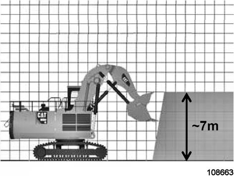
Example situation: The material to dig is e.g. free - dig overburden.
- Material characteristics is – sticky / in situ,
- It is a steep slope - angle is approx. 60°.
The optimal bench height is for tough digging (Fig. 2-140:):
- Cabin roof height (e.g. for 6030 FS): ~7m
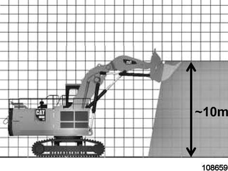
The maximum bench height is (Fig. 2-141:):
-75% of the maximum vertical reach (e.g. for the 6030 FS): 13.9 m x 0.75 ≈ 10 m
(These are rules of thumb, they are a guide only, values depend on the material conditions).
Bench Height on Flat Slopes
Bench Height on Flat Slopes
Example situation:
The material to load is e.g. well blasted pile.
- Material characteristics is – free flowing / loose, material has the tendency to roll down.
- It is a flat slope – angle is approx. ≤ 60°.
The maximum bench height is (Fig. 2-142: and Fig. 2-143:):
-Maximum vertical reach (e.g. for 6030 FS): ~14 m
(This is a rule of thumb, a guide only, value depends on the material conditions).
Bench Heights – Recommendations for FS - Machines, table
Basic setup at a bench
The undercarriage should be positioned at 45° to the face (Fig. 2-144: and Fig. 2-145:).
Sprocket / final drives shall always point away from the face.
Truck position on the left hand (cab) side of the shovel.

Shovel operator and truck driver have eye contact.
The 45° position towards the digging face allows quick escape in case of a face collapse (Fig. 2-145:).
All rollers are not exposed to damage.
Less dirt on RH from material falling from the face track.
The digging forces are transmitted lengthwise through the track pad grousers into the ground (Fig. 2-146:).
Traction is optimal in this position.
A crosswise position would apply side load to the rollers.