8 minute read
Traveling – Basic Movements


Traveling movement is controlled by means of the travel pedals (112 and 113, Fig. 2-216:). The travel pedals return automatically to their neutral positions when released.
During traveling, an acoustic warning signal sounds (Travel Alarm).
All instructions with regard to travel direction control are applicable only as long as the crawler tracks have sufficient grip and do not slip.
For information regarding traveling speed refer to section “Traveling speed – adjust”.
The information given in this section are applicable when traveling on level ground and also when traveling the machine on moderate inclinations, e. g.on haulroads. For additional information about traveling on steep ramps and steep slopes refer to section “Traveling uphill and downhill on ramps and steep slopes”.
Operate travel pedals gently
Accelerate and decelerate travel movements gently. Sudden acceleration and abrupt braking from full speed are a huge strain for the machine. Avoid aggressive traveling practices.
Traveling straight forward
Move both travel pedals in the direction of the front window. The machine moves in direction of the idlers (Fig. 2-217:). To stop travel movement, release the pedals, they return in neutral position.
Note: Reverse the hydraulic shovel only over short distances and with the assistance of marshallers because of restricted rear-view conditions.
Traveling straight backward
Move both travel pedals in the direction of the operator’s seat. The machine moves in direction of the final drives (Fig. 2-218:). To stop travel movement, release the pedals, they return in neutral position.
Turning
Note:
Traveling through curves in a single sharp turn should be avoided whenever possible. When traveling through curves it is necessary to divide the curve movement into small gradual turns followed by a short distance of straight travel. Doing so prevents from material build up between rollers and tracks which could lead in excessive wear and damage of undercarriage components.
Turning, make a gradual right turn forward
Move the left travel pedal in the direction of the front window. Leave the right travel pedal in neutral. The machine moves in a gradual right turn forward (Fig. 2-219:). To stop the turn, release the pedal, it returns in neutral position.
Turning, make a gradual left turn forward
Move the right travel pedal in the direction of the front window. Leave the left travel pedal in neutral. The machine moves in a gradual left turn forward (Fig. 2-220:). To stop the turn, release the pedal, it returns in neutral position.
Turning, make a gradual right turn backward
Move the left travel pedal in the direction of the operator’s seat. Leave the right travel pedal in neutral. The machine moves in a gradual right turn backward (Fig. 2-221:). To stop the turn, release the pedal, it returns in neutral position.
Turning, make a gradual left turn backward
Move the right travel pedal in the direction of the operator’s seat. Leave the left travel pedal in neutral. The machine moves in a gradual left turn backward (Fig. 2-222:). To stop the turn, release the pedal, it returns in neutral position.
Note:
Select slow speed level. To do so, switch speed level switch (72, Fig. 2-228:) to the left.
Change the position of the undercarriage only by turning forwards/backwards (Fig. 2-223:).
Turning to the left:
forwards from pos. 1 to pos. 2
backwards from pos. 2 to pos. 3
forwards from pos. 3 to pos. 4
The same procedure should be adopted if the hydraulic shovel is to be driven out of depressions (Fig. 2-224:):
Turning to the left from pos. 1 to pos. 2
Turning to the right from pos. 2 to pos. 3
Counter-rotation turns / Turning on the spot
Note:
Counter rotational turns/turning on the spot in a single sharp turn should be avoided whenever possible.
When turning in single sharp turns, the machine can bury itself - especially in soft material. When turning on the spot it is necessary to divide the turn movement into small gradual turns followed by a short distance of straight travel. Doing so prevents from material build up between rollers and tracks which could lead in excessive wear and damage of undercarriage components.
Select slow speed level. To do so, switch speed level switch (72, Fig. 2-228:) to the left. Change speed level only when the hydraulic shovel is stationary.
Counter-rotation turn to the right / Turning on the spot
Move the right travel pedal in the direction of the operator’s seat. Move the left travel pedal in the direction of the front window. The machine moves in a gradual turn to the right (Fig. 2-225:). To stop the turn, release the pedals, they return in neutral position.
Counter-rotation turn to the left / Turning on the spot
Move the left travel pedal in the direction of the operator’s seat. Move the right travel pedal in the direction of the front window. The machine moves in a gradual turn to the left (Fig. 2-226:). To stop the turn, release the pedals, they return in neutral position.
Track Parking Brake – set/release
The hydraulic shovel is equipped with four traveling gear brakes which are integrated in the travel drives.
The traveling gear brakes are parking brakes. They protect the hydraulic shovel from rolling forwards or backwards. When the machine is parked, travel brakes are activated automatically. The brakes are deactivated when the travel pedals are activated allowing the machine to travel.
Note:
As travel brakes are deactivated, machine could slightly move in direction of excavating during operation.
Whenever loading operation is interrupted, rest the attachment on the ground. This avoids slight movement of the machine and possible consequential damage of lowered ladder, in case ignition remains engaged.
Traveling speed – adjust
All instructions with regard to traveling speed regulation are applicable only as long as the crawler tracks have sufficient grip and do not slip.
Select
Travel Speed Level
Note: Change speed level only when the hydraulic shovel is stationary.
Switch (72, Fig. 2-228:) to the left = slow gear. All forward/reverse travel movements are possible with this gear.
Switch (72) to the right = fast gear. All forward/reverse travel movements are possible with this gear.
Adjust the traveling speed
Depress travel pedals (112 and 113, Fig. 2-228:) fully or partially depending on the travel speed wanted. Releasing the travel pedals brings the shovel to a standstill.
For Service and Maintenance purposes the traveling gear brakes can also be applied with switch (63, Fig. 2-227:).
Actuate this switch only when the hydraulic shovel is stationary. Do not use this switch while the hydraulic shovel is still in motion. Risk of damage to the brakes and the travel gearboxes.
Press the switch face with the symbol (63): The parking brake is applied permanently. The hydraulic shovel cannot be moved. For more detailed information refer to the Service Manual, chapters eight and nine.
Traveling uphill and downhill on ramps and steep slopes
Note:
When traveling uphill or downhill on ramps and steep slopes, the travel drives must always face downhill (1, Fig. 2-255: to Fig. 2-232:). Otherwise track tension loss may occur. Do not exceed the maximum machine inclination when traveling uphill or downhill (refer to section “Maximum machine inclinations”).
Read and observe section "Traveling – Safety instructions".
Traveling uphill:
Select slow speed level. To do so, switch speed level switch (72, Fig. 2-233:) to the left. Note: Change speed level only when the hydraulic shovel is stationary.
Bring shovel in a position shown in Fig. 2-229: and Fig. 2-230:. The final drives (1) and the counterweight are facing downhill.
Depress travel pedals (112 and 113, Fig. 2-233:).
Traveling downhill:
Select slow speed level. To do so, switch speed level switch (72, Fig. 2-233:) to the left. Note: Change speed level only when the hydraulic shovel is stationary.
Bring shovel in a position shown in Fig. 2-231: and Fig. 2-232:. The final drives (1) are facing downhill. The counterweight is facing uphill.
Depress travel pedals (112 and 113, Fig. 2-233:).
Note:
Avoid changing the direction of travel on a slope. Changing the direction of travel on a slope could result in tipping or side slipping of the machine. Be extremely careful on slippery and greasy ground. The machine may slip.
Do not travel across slopes.
Keep the working attachment close to the ground. Be careful to avoid any ground condition which could cause the machine to tip. Tipping can occur when you travel on hills, on banks or on slopes.
If the machine begins to sideslip on a grade, immediately dump the load and turn the machine uphill.
Traveling speed on ramps and slopeschange
Select slow speed level. To do so, switch speed level switch (72, Fig. 2-233:) to the left. Note: Change speed level only when the hydraulic shovel is stationary.
Depress travel pedals (112 and 113, Fig. 2-233:) fully to the limit stop.
When traveling downhill, the travel retarder valve acts as a speed limiter.
If the traveling speed nevertheless becomes too high when traveling downhill, release travel pedals (112 and 113) to stop the shovel.
Traveling over long distances
Note:
Travel only forwards with the hydraulic shovel in its basic position.
Traveling backwards over longer distances could wear out or damage parts of the undercarriage. Read and observe section "Traveling – Safety instructions".
Do not exceed the maximum machine inclination (refer to section “Maximum machine inclinations”).
When traveling, pay attention to sufficient headroom, e. g. under cable bridges or high-tension cables.
Lower the attachment when traveling underneath obstacles.
Keep the face shovel or the backhoe bucket close to the ground. For a more uniform loading of the tracks, the attachment must, however, be kept at a steep angle (Fig. 2-234: and Fig. 2-235:).
Notice
If non-OEM buckets are installed, be careful to avoid contact between bucket and machine (i.e. boom).
Set the upper structure holding brake.
Recommended position of the face shovel attachment (Fig. 2-234:):
Fully extend boom cylinder (1).
Retract bucket cylinder (2).
Retract stick cylinder (3).
Retract bucket cylinder (2) and stick cylinder (3) to such an extent as to reach the position of the attachment shown in (Fig. 2-234:).
Recommended position of the backhoe bucket attachment (Fig. 2-235:):
Fully extend boom cylinder (1).
Extend backhoe cylinder (2).
Extend stick cylinder (3).
Extend backhoe cylinder (2) and stick cylinder (3) to such an extent as to reach the position of the attachment shown in (Fig. 2-235:).
If the attachment position must be changed:
Stop the hydraulic shovel,
Change the position,
Continue to travel.
Upper structure holding brake –set/release
The hydraulic shovel is equipped with four upper structure holding brakes which are integrated in the swing gearboxes. The upper structure holding brakes lock the upper structure with respect to the undercarriage.
The gearbox brakes are holding brakes only.
Note:
Do not press the button unless the upper structure is stationary. Do not use this button while the upper structure is still in motion. Risk of damage to the brakes and the slewing gears.
Apply the holding brake:
When the hydraulic shovel is parked.
When traveling longer distances.
To apply the holding brakes, press switch (61, Fig. 2-236:).
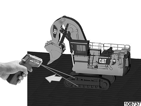
Track roller temperature – check
After traveling for 15 minutes without interruption, stop the hydraulic shovel and check the temperature of the track rollers.
If you use an infrared thermometer, you can measure the temperature from some distance (Fig. 2-237:).
If the temperature is below 70 °C (158 °F):
Continue traveling.
If the temperature is between 70 °C and 90 °C (158 °F and 194 °F):
Monitor the temperature of the track rollers.
Continue traveling but check temperature in short intervals.
In case of higher temperatures above 90 °C (194 °F):
Stop traveling.
Resume traveling only after the track rollers have cooled down to approx. 40° C (104°F).
Note:
Do not walk beside the machine and try to cool down track rollers by hand with a bucket of water or with a water hose.
In principle it is possible to use a water truck to spray water on the track rollers from a safe distance. This will rapidly cool down the track rollers.