UENR1277 July 2011
Schematic Location
Component
Machine Location
Actuator - Water Valve
F-14
1
Relay - Machine Power Distribution
D-10
46
Alarm - Action
H-2
2
Relay - Main Power
C-10
47
134-2540
Resistor:
CAN A CAN B 1, 2 CAN C 1, 2 CAN D Radar CAN
167-7801
Resistor:
Pull-Up
Resistance (Ohms)¹
120 ± 10%
390 ± 5%
Alarm - Audible
H-8
3
Relay - Oil Cooler
B-9
48
0041
8 Volt DC Supply
Antenna - Product Link
E-4
4
Relay - Prelube Priming
C-9
49
0168
Electrical System Voltage
Breaker - Engine ECM
C-10
5
Relay - Starter Lockout
B-9
50
0296
Transmission Control
Breaker - Running Lamp
C-10
6
Resistor - CAN A
F-1
51
0350
Lift Linkage Position Sensor
Control - Advisor
G-2
7
Resistor - CAN B1
F-1
52
0351
Tilt Linkage Position Sensor
Control - HVAC
F-4
8
Resistor - CAN B 2
F-4
53
0352
Lift Lever Sensor
Control - Implement
J-5
9
Resistor - CAN C 1
F-4
54
0353
Tilt Lever Sensor
Control - Indication Display
E-2
10
Resistor - CAN C 2
E-4
55
0354
Raise Solenoid #1
0355
Lower Solenoid #1
Control - Transmission
G-5
12
Resistor - Pull-Up
0356
Dump Solenoid #1
Control - Vims Main
D-4
13
Resistor - Radar Can Term
0357
Rackback Solenoid #1
Control - Vims Smart Signal
C-4
14
Sensor - Lift Lever Position
I-3
59
0358
Implement Pilot Pressure Supply Solenoid
Converter - 10A
H-10
15
Sensor - Louver Temp
H-2
60
0434
Hydraulic Pilot Oil Pressure Sensor
Converter - 10A (For Comm Radio)
H-10
16
Sensor - Recirc Filt Temp
F-4
61
0490
Implement Lockout Switch
Ground - 1
D-5
17
Sensor - Throttle Position
C-2
62
¹ With increasing pressure the closed condition can be maintained up to 2800 kPa (405 psi), with decreasing pressure the closed condition can be maintained down to 170 kPa (25 psi).
0590
Engine Control Module
Ground - 2
C-4
18
Sensor - Tilt Lever Position
I-3
63
² Contact position at the contacts of the harness connector.
0592
Raise Solenoid #2
Ground - 3
B-10
19
Switch - AC Hi Low
F-13
64
0593
Lower Solenoid #2
Ground - 4
B-4
20
Switch - AC Low
F-13
65
0594
Rackback Solenoid #2
Ground - 5
G-5
21
Switch - Air Conditioner Control
H-1
66
0595
Dump Solenoid #2
Ground - Cab 1
C-8
22
Switch - Beacon
G-1
67
0600
Hydraulic Oil Temperature Sensor
Ground - Cab 2
B-8
23
Switch - Camera Sprayer
E-1
68
0800
VIMS Main Module
Ground - Right Rear Cab
B-12
24
Switch - Dual Wiper
I-10
69
1326
ECM Location Code
Motor - Blower
G-14
25
Switch - Front Floods
H-1
70
1482
10 Volt Sensor DC Power Supply
Motor - Front Washer
F-13
26
Switch - Front Intermittent Wiper
I-10
71
1569
Left Front Implement Pump Solenoid
Motor - Front Wiper
C-2
27
Switch - HID Lamp
H-1
72
1570
Left Rear Implement Pump Solenoid
Motor - Left Wiper
E-13
28
Switch - Horn 1
I-3
73
2405
Center Implement Pump Solenoid
Motor - LH Door Washer
E-13
29
Switch - Ignition
I-1
74
2408
Left Lift Float Solenoid
Motor - Precleaner
D-13
30
Switch - Implement Lockout
H-3
75
2409
Right Lift Float Solenoid
Motor - Rear Washer
E-13
31
Switch - Payload Store
H-3
76
2415
Implement Left Main Valve Supply Pressure Sensor
Motor - Rear Wiper
D-12
32
Switch - Rear Flood Lamp
G-1
77
2416
Implement Right Main Valve Supply Pressure Sensor
Motor - RH Door Washer
E-13
33
Switch - Rear Intermittent Wiper
H-10
78
3510
Right Implement Pump Solenoid
Motor - Right Wiper
E-13
34
Switch - RH Service Brake Pedal
D-2
79
Motor - Sprayer Washer
F-13
35
Switch - Running Lamp
G-1
80
Panel - HVAC
H-1
36
Switch - Stairway Access Lights
F-1
81
Radio - Product Link
E-4
37
Switch - Stic Lockout Control
I-3
82
8 Volt DC Supply
Relay - Backlight
C-9
38
Switch - Stop Lamp
I-2
83
0070
Parking Brake Switch
Relay - Backup Alarm
C-9
39
Switch - Dome Lamp
D-2
84
0096
Fuel Level Sensor
Relay - Engine Shutdown
D-9
40
Switch - Throttle Lock Set 1
H-3
85
0144
Backup Alarm Relay
Relay - Forward Horn
C-9
41
Switch - Torque Converter Pedal Pos
D-2
86
0168
Electrical System Voltage
Relay - Front Floods
E-9
42
Switch - Throttle Lock Resume 1
H-3
87
0171
Ambient Air Temperature Sensor
Relay - Front Floods 2
C-9
43
Switch - Washer Liquid Level
D-13
88
0177
Transmission Oil Temperature Sensor
Relay - Front HID
C-9
44
Thermostat - HVAC Evaporator
F-14
89
0190
Engine Speed Sensor
Relay - Heated Mirrors
B-9
45
0262
5 Volt Sensor DC Power Supply
Machine locations are repeated for components located close together.
0348
Transmission Lock Switch
0378
Machine Auto Lube Solenoid
0379
Machine Auto Lube Pressure Sensor
0427
Front Axle Oil Temperature Sensor
0428
Rear Axle Oil Temperature Sensor
0444
Starter Motor Relay
Control - Stick
Transmission Control (MID No. 081) CID 0041
Component
I-3
11
Resistor - CAN D
E-4 I-1
57
C-13
58
149-6371
AC Low Pressure
114-5333
AC High/Low Pressure
Actuate
Deactuate
103.4 ± 13.8 kPa
34.5 ± 13.8 kPa
Contact Position
(14.9 ± 2 psi)
(5 ± 2 psi)
275 to 1750 kPa¹
-
(39.9 to 253.8 psi)
-
Normally Open Normally Open²
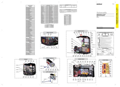
994H Wheel Loader Electrical System
Connector Location - Volume 1 Connector Number CONN 1
Schematic Location G-13
CONN 2
F-13
CONN 3
D-13
CONN 4
B-12
CONN 5
B-12
CONN 6
D-12
CONN 7
D-12
CONN 8
E-12
CONN 9
F-12
CONN 10
G-12
CONN 11
I-12
CONN 12
H-10 H-10
CONN 13 CONN 14 CONN 15
H-10 I-9
CONN 16
I-9
CONN 17
I-5
CONN 18
I-5
CONN 19
H-5
CONN 20
I-2
CONN 21
I-1
994H: DWC1-UP
F-1 The connectors shown in this chart are for harness to harness connectors. Connectors that join a harness to a component are generally located at or near the component. See the Component Location Chart.
Related Electrical Service Manuals Title
Form Number UENR0751
VIMS 3G Control:
UENR0787
Monitoring System Display
CIOPS Control:
UENR1274
0590
Engine Control Module
Monitor Control:
UENR2437
0596
Implement Control
Implement Control:
UENR2437
0621
Downshift Switch
0622
Upshift Switch
0623
Directional Switch
0626
Steering/Transmission Lock Switch
0627
Parking Brake Pressure Switch
0672
Torque Converter Output Speed Sensor
0673
Transmission Output Speed Sensor #2
0678
Torque Converter Impeller Clutch Solenoid
0679
Torque Converter Lockup Clutch Solenoid
0828
Right Exhaust Temperature Sensor
0849
System Air Pressure Sensor
0967
Machine Application
1326
ECM Location Code
1401
Transmission Solenoid 1
1402
Transmission Solenoid 2
1403
Transmission Solenoid 3
1404
Transmission Solenoid 4
1405
Transmission Solenoid 5
1482
10 Volt Sensor DC Power Supply
0588
56
Function
CONN 22
Transmission Control:
0585
Off-Machine Switch Specification Part No.
Transmission Output Speed Sensor #1
Volume 1 of 2: Cab Wiring © 2011 Caterpillar, All Rights Reserved
INSIDE RIGHT 69
RIGHT FRONT CONN: 20
1712
Torque Converter Pedal Position Sensor
2341
Brake Cooling Oil Tank Temperature Sensor
2984
Auto Lube Pump Outlet Pressure Sensor
3467
Main Power Relay
3470
Machine Power Distribution Relay
3583
Switch Panel #1
14
7
58
3
36
51
57
72
CID
13
0248
CAT Data Link
2348
SAE J1939 Data Link #2
3317
MediumObjectDetectionSensor#1
3318
MediumObjectDetectionSensor#2
Temperature Symbol
Switch (Normally Closed): A switch that will open at a specified point (temp, press, etc.). No circle indicates that the wire cannot be disconnected from the component.
3330
MediumRangeObjectDetectionSensor#2PowerSupply
3331
MediumRangeObjectDetectionSensor#3PowerSupply
Reed Switch: A switch whose contacts are controlled by a magnet. A magnet closes the contacts of a normally open reed switch; it opens the contacts of a normally closed reed switch.
81
Component
0096
Fuel Level Sensor
0145
12 Volt DC Power Supply
0171
Ambient Air Temperature Sensor
0262
5 Volt Sensor DC Power Supply
0296
Transmission Control
0350
Lift Linkage Position Sensor
0425
Front Brake Oil Pressure Sensor
0426
Rear Brake Oil Pressure Sensor
0427
Front Axle Oil Temperature Sensor
0428
Rear Axle Oil Temperature Sensor
0430
Steering Pilot Oil Pressure Sensor
0590
Engine Control Module
0596
Implement Control
0600
Hydraulic Oil Temperature Sensor
0800
VIMS Main Module
0890
Telemetry Data Link
2183
Payload Monitoring System
2413
Left Steering Pump Oil Pressure Sensor
2414
Center Steering Pump Oil Pressure Sensor
2448
Graphical Display Module
Ground (Case): This indicates that the component does not have a wire connected to ground. It is grounded by being fastened to the machine.
18
VIMS Control (MID No. 049)
Steering Oil Temperature Sensor
Ground (Wired): This indicates that the component is connected to a grounded wire. The grounded wire is fastened to the machine.
80
MediumRangeObjectDetectionSensor#1PowerSupply
0075
Sender: A component that is used with a temperature or pressure gauge. The sender measures the temperature or pressure. Its resistance changes to give an indication to the gauge of the temperature or pressure.
T
82
Relay (Magnetic Switch): A relay is an electrical component that is activated by electricity. It has a coil that makes an electromagnet when current flows through it. The electromagnet can open or close the switch part of the relay.
CONN: 22
Solenoid: A solenoid is an electrical component that is activated by electricity. It has a coil that makes an electromagnet when current flows through it. The electromagnet can open or close a valve or move a piece of metal that can do work.
56 CONN: 12
16
CONN: 13
2
Magnetic Latch Solenoid: A magnetic latch solenoid is an electrical component that is activated by electricity and held latched by a permanent magnet. It has two coils (latch and unlatch) that make electromagnet when current flows through them. It also has an internal switch that places the latch coil circuit open at the time the coil latches.
CONN: 21
61 27
Harness and Wire Symbols Wire, Cable, or Harness Assembly Identification: Includes Harness Identification Letters and Harness Connector Serialization Codes (see sample).
74 86 84
Electrical System Voltage
0271
Action Alarm
0820
Keypad Data Link
0821
Display Power Supply
0822
LCD Back Light Power Supply
Plug
68 84
62
52
53
78
9
17
L-C12 3E-5179
Harness Connector Serialization Code: The "C" stands for "Connector" and the number indicates which connector in the harness (C1, C2, C3, ...).
Part Number: for Connector Receptacle
2
Component
0168
L-C12 3E-5179
1
Part Number: for Connector Plug
12 Volt DC Power Supply
Harness Identification Letter(s): (A, B, C, ..., AA, AB, AC, ...)
AG-C4 111-7898
Advisor Control (MID No. 053) 0145
Circuit Breaker Symbol
Switch (Normally Open): A switch that will close at a specified point (temp, press, etc.). The circle indicates that the component has screw terminals and a wire can be disconnected from it.
67
MediumObjectDetectionSensor#3
8 Volt DC Supply
Flow Symbol
Symbols and Definitions
71
0041
Level Symbol
Fuse: A component in an electrical circuit that will open the circuit if too much current flows through it.
3319
CID
Pressure Symbol
77
3329
CID
Symbols
T
Component SAE J1939 Data Link
Harness And Wire Electrical Schematic Symbols
70
CIOPS Control (MID No. 134) 0247
Printed in U.S.A.
Receptacle Pin or Socket Number
1 2
Deutsch connector: Typical representation of a Deutsch connector. The plug contains all sockets and the receptacle contains all pins.
1 2
Sure-Seal connector: Typical representation of a Sure-Seal connector. The plug and receptacle contain both pins and sockets.
5A Fuse (5 Amps)
9X-1123
325-AG135 PK-14 Harness identification code: This example indicates wire group 325, wire 135 in harness "AG".
Wire Gauge Wire Color
66
12
RIGHT CONSOLE FRONT 34
INSIDE REAR
73 15
28
FUSE PANEL
CONN: 3
32
26
CONN: 1
29
31
33
65
64
35
88 30
CONN: 4
39
38
43
6
41
44
50
5
48
46
45
47
CONN: 14 CONN: 6
CONN: 18 CONN: 16
CONN: 11
CONN: 19 CONN: 15
75
63
59
85
LEFT CONSOLE
CONN: 5
87
76
CONN: 7 21 22 CONN: 8
79
37
4
10
42
CONN: 9
19 11 CONN: 17
54
55
23
24
CONN: 10 82
1
89
CONN: 2
25
60
8
Component Part Number
40
49
(Dimensions: 48 inches x 35 inches)
Component
Machine Location
Component Description
36 Page,
Schematic Location
Component
Part No.
UENR1277 VOL 1 of 2
CID
Resistor Specifications - Volume 1
Component Location - Volume 1
Component Identifiers (CID¹) Module Identifier (MID²) Implement Control (MID No. 082)