42
Component Location - Volume 2 Machine Location*
B-17
H-17, P-17
ALARM - AUDIBLE BACKUP
J-15
I-28, Q-28
1
Injector Cylinder 1
ALARM - AUDIBLE L BACKUP
K-15
I-28, T-28
2
Injector Cylinder 2
ALTERNATOR - 1
G-17
33
3
Injector Cylinder 3
ALTERNATOR - 2
F-17
45
4
Injector Cylinder 4
ARC SUPRESSOR - A/C
I-17
32
5
Injector Cylinder 5
BATTERIES
K-12
H-18, O-18
6
Injector Cylinder 6
BATTERIES
K-12
H-18, P-18
7
Injector Cylinder 7
BATTERIES
K-12
H-18, U-18
8
Injector Cylinder 8
BLOCK - FUSE (240 VAC)
E-12
24
9
Injector Cylinder 9
BLOCK - JUNCTION
H-12
H-18, V-18
10
Injector Cylinder 10
BLOCK - TERMINAL (240VAC)
C-12
23
11
Injector Cylinder 11
BREAKER - ADEM
G-11
H-18, V-18
12
Injector Cylinder 12
BREAKER - ALTERNATOR 1
H-11
H-18, V-18
13
Injector Cylinder 13
BREAKER - ALTERNATOR 2
G-11
H-18, V-18
14
Injector Cylinder 14
BREAKER - ENGINE PRELUBE
G-11
H-18, V-18
15
Injector Cylinder 15
BREAKER - KEY
H-11
H-18, V-18
16
Injector Cylinder 16
BREAKER - MAIN
H-11
H-18, V-18
91
Throttle Position
BREAKER - RUNNING LAMPS
H-11
H-18, V-18
101
Crankcase Pressure
CLUTCH - A/C COMPRESSOR
I-17
44
E-18
20
CID
Component
Engine Coolant Temperature
CONTROL - ADEM
168
System Voltage
CONTROL - IMPLEMENT
F-6
H-18, V-18
190
Engine Speed signal
CONTROL - TRANSMISSION
G-6
H-16, V-16
253
Personality Module
CONTROL - VIMS
J-6
H-18, V-18
261
Engine Timing calibration
DIODES - RELAY
L-9
H-16, V-16
262
5 Volt Sensor DC Power Supply
FUSE PANEL
K-11
H-18, V-18
263
Digital Sensor supply
HEATER - ENGINE OIL 1 (240VAC)
C-11
49
267
Incorrect Engine Shutdown Switch inputs
HEATER - ENGINE OIL 2 (240VAC)
C-11
28
268
Check Programmable Parameters
HEATER - JACKET WATER 1 (240VAC)
D-11
55
273
Turbo Outlet Pressure
HEATER - JACKET WATER 2 (240VAC)
D-11
19
274
Atmospheric Pressure
HEATER - JACKET WATER 3 (240VAC)
D-11
47
275
Right Turbo Inlet Pressure
HEATER - JACKET WATER 4 (240VAC)
D-11
59
276
Left Turbo Inlet Pressure
HOURMETER
J-18
C-24, W-24
291
Engine Cooling Fan Solenoid
INDICATOR - START LOCKOUT
J-18
C-24, W-24
296
Unable to communicate with Transmission ECM
INJECTOR - 1
G-18
1
298
Incorrect Service Brake Pedal Switch inputs
INJECTOR - 10
F-17
10
338
Pre-Lube Relay
INJECTOR - 11
F-18
11
542
Unfiltered Engine Oil Pressure
INJECTOR - 12
E-17
12
543
Filtered Engine Oil Pressure
INJECTOR - 13
F-18
13
544
Engine Cooling Fan Speed
INJECTOR - 14
E-17
14
546
Ether Hold Relay
INJECTOR - 15
E-18
15
800
Unable to communicate with VIMS
INJECTOR - 16
E-17
16
827
Left Exhaust Temperature
INJECTOR - 2
F-17
2
828
Right Exhaust Temperature
INJECTOR - 3
G-18
3
829
Rear Aftercool Temperature
INJECTOR - 4
F-17
4
1495
Injector Trim Codes Not Programmed
INJECTOR - 5
F-18
5
Engine Oil Renewal System
INJECTOR - 6
F-17
6
INJECTOR - 7
F-18
7
110
2271
Vital Information Management System (VIMS) ECM (MID No. 049) CID
Component
0041
8 Volt DC Supply
0075
Steering Oil Temperature Sensor
0096
Fuel Level Sensor
0127
Transmission Oil Pressure Sensor
0145
12 Volt DC Supply
0171
Ambient Air Temperature Sensor
0248
Cat Data Link
0267
Remote Shutdown Input
0271
Action Alarm
0296
Transmission Control
0324
Warning Lamp (Action)
0350
Lift Linkage Position Sensor
0364
Lift Cylinder Head Pressure Sensor
0371
Operator Horn Solenoid
0425
Front Brake Oil Pressure Sensor
0426
Rear Brake Oil Pressure Sensor
0427
Front Axel Oil Temperature Sensor
0428
Rear Axel Oil Temperature Sensor
0429
Steering Main Pump Oil Pressure Sensor
0430
Steering Pilot Oil Pressure Sensor
0434
Hydraulic Pilot Oil Pressure Sensor
0436
Torque Converter Oil Pressure Sensor
0457
Brake Oil Temperature Sensor
0458
Tilt Cylinder Rod Pressure Sensor
0590
Engine Control Module
0596
Implement Control
0600
Hydraulic Oil Temperature Sensor
0650
Harness Code
0767
Fixed Implement Pump Oil Pressure Sensor
0809
Speedometer/Tachometer (No. 1)
0810
Speedometer/Tachometer (No. 2)
0811
Gauge Cluster (No. 1)
0812
Gauge Cluster (No. 2)
0813
Gauge Cluster (No. 3)
0814
Gauge Cluster (No. 4)
0815
Message Center (No. 1)
0816
Message Center (No. 2)
0817
ECM Internal Backup Battery
0819
Display Data Link
0820
Keypad Data Link
0822
LCD Back light Power Supply
0823
Service Lamp
0826
Torque Converter Oil Temperature Sensor
0849
System Air Pressure Sensor
0860
Front Pump Drive Oil Temperature Sensor
CID
INLET EXHAUST TEMP SENSOR
EFPP/ALTERNATOR GND
55 JACKET WATER
52
HEATER 1 (240 VAC)
LAMP - LH PLATFORM FLOOD
B-4
H-16, W-16
LAMP - R STOP TAIL
J-15
LAMP - RH BUCKET FLOOD
B-5
F-8, S-8
LAMP - RH ENGINE FLOOD
K-15
H-25, Q-25
LAMP - RH PLATFORM FLOOD
B-17
H-16, N-16
LAMP - RH REAR FLOOD OR HID
J-15
H-28, P-28
LAMP - RH RUNNING
C-4
I-10, O-10
LAMP - RH TOWER FLOOD 1
C-4
I-10, O-10
B-4
I-10, O-10
LAMP - VIMS
K-15
G-28, U-28
LED - OIL RECOVERY SYS TANK FULL IND
A-18
C-16, P-16
LED - TRANSMISSION LOCKOUT IND
J-18
C-24, W-24
MOTOR - ELECT FUEL PRIMING PUNP
J-17
50
MOTOR - PRELUBRICATION
J-14
D-25, S-25
RELAY - BACKLIGHT 1
K-8
H-16, V-16
RELAY - BACKUP ALARM
I-8
H-16, V-16
RELAY - BUCKE FLOOD
I-8
H-16, V-16
CONNECTOR 4O
36
RESISTOR 1 FAN SPEED
35
ALTERNATOR 1 A/C ARC SUPRESSOR
31
A/C REFRIGERANT SW
30
OIL PRESURE SENSOR (UNFILTERED)
I-8
H-16, V-16
RELAY - PRELUBE PRIMING
G-8
H-16, V-16
RELAY - ROPS FR
J-8
H-16, V-16
RELAY - ROPS HID 1
H-8
H-16, V-16
RELAY - ROPS HID 2
F-8
H-16, V-16
RELAY - ROPS RR
J-8
H-16, V-16
RELAY - START
K-8
H-16, V-16
RESISTOR - 1 FAN SPEED
G-18
35
RESISTOR - 2 CAN DATA LINK
H-16
22
SENSOR - AFTERCOOLER TEMP
H-17
57
SENSOR - AMBIENT AIR TEMPERATURE
K-14
H-16, S-16
SENSOR - ATMOSPHERIC PRESSURE
I-18
21
29 25 OIL PRESSURE
ENGINE OIL HEATER 2 (240 VAC)
SENSOR (FILTERED)
28
LOW OIL/VMS ADD OIL SWITCH
27
26 VERY LOW OIL SWITCH
Component
Schematic Location
Machine Location
K-18
T-40, C-40
SENSOR - AUTOLUBE PRESS
A-4
H-17, U-17
ACTUATOR - WATER VALVE
SENSOR - AXEL TEMPERATURE (REAR)
A-18
C-20, S-20
ALARM - AUDIBLE FOR CAES
B-9
E-38, Q-38
SENSOR - BRAKE C00LING OIL TEMP
B-15
H-20, Q-20
BATTERY - BACKUP FOR CAES
J-3
L-41, U-41
H-2
M-41, Q-41
SENSOR - COOLANT TEMPERATURE
H-17
39
BEACON 1
SENSOR - CRANKCASE PRESSURE
I-18
52
BEACON 2
H-2
M-41, W-41
CAMERA - REAR VIEW
E-13
I-27, R-27
SENSOR - FRONT AXEL OIL TEMP
A-6
C-11, S-11
SENSOR - FRONT PUMP DRIVE OIL TEMP
B-7
H-14, S-14
CIGAR LIGHTER - 12V
G-7
E-37, Q-37
D-8
G-37, Q-37
SENSOR - FUEL LEVEL
K-14
D-26,T-26
CONTROL - CAES NAVIGATOR
SENSOR - IMPELLER CLUTCH PRESS
D-15
F-19, S-19
CONTROL GP - GATEWAY
I-4
E-40, Q-40
A-5
E-12, Q-12
CONTROL GP - STICK
J-12
E-35, V-35
A-6
E-9, S-9
CONVERTER - VOLTAGE
B-5
J-38, T-38
G-17
42
CONVERTER - VOLTAGE FOR CAES
L-3
K-36, O-36
G-11
E-33, U-33 G-33, S-33
SENSOR - LH TURBO INLET PRESSURE
H-18
40
DISPLAY - GAGE CLUSTER
SENSOR - MAGNETIC TACH
K-17
18
DISPLAY - MESSAGE CENTER
G-11
0138
Switch (Reduced Rimpull Selection)
SENSOR - PRIMARY CAM SPEED/TIMING
G-18
17
0168
Electrical System Voltage
SENSOR - RH TURBO INLET PRESSURE
H-17
43
LAMP - LADDER 1
D-4
L-18, T-18
0190
Speed Signal (Engine)
SENSOR - STEERING OIL TEMP
B-15
H-20, R-20
LAMP - LADDER 2
C-4
L-18, Q-18
0348
Switch (Transmission Lock)
SENSOR - TILT KICKOUT
A-5
H-7, R-7
LAMP - LH FRONT FLOOD 2
G-2
L-14, U-14
0378
Solenoid (Machine Autolube)
SENSOR - TIMING CAL PLUG
I-17
56
LAMP - LH FRONT ROPS FLOOD
G-2
L-14, U-14
0379
Pressure Sensor (Machine Autolube)
SENSOR - TORQUE CONV OIL TEMP
C-15
F-19, Q-19
LAMP - LH ROPS HID 1
H-2
L-14, U-14
0444
Magnetic Switch (Start Relay)
SENSOR - TORQUE CONV OUTPUT SPEED
D-15
F-19, S-19
LAMP - LH ROPS HID 2
H-2
L-14, U-14
0585
Speed Sensor No. 1 (Transmission Output )
SENSOR - TRANS SPEED 1
F-11
D-17, R-17
LAMP - PANEL 2
H-7
D-36, Q-36
D17, R-17
LAMP - PANEL 3
H-7
D-36, Q-36
H-7
D-36, Q-36
0590
Electronic Control Module (Engine)
0596
Electronic Control Module (Implement)
SENSOR - TURBO OUTLET PRESSURE
I-18
38
LAMP - PANEL 4
0603
Pressure Sensor (Torque ConverterImpeller Clutch)
SENSOR LIFT CYL HEAD END PRESS
B-8
E-14, T-14
LAMP - PANEL 5
H-7
D-36, Q-36
0623
Switch (Transmission Direction)
SENSOR LIFT POSITION
B-5
H-13, P-13
LAMP - PANEL 6
H-7
D-36, Q-36
0626
Switch (Steering/Transmission Lock)
SENSOR -RH TURBO IN EXHAUST TEMP
H-17
58
LAMP - PANEL 7
E-7
D-36, Q-36
0627
Pressure Switch (Parking Brake)
SOLENOID - AIR START VALVE
A-17
LAMP - RH FRONT FLOOD 2
G2
L-14, P-14
0650
Harness Code
SOLENOID - AUTOLUBE
A-4
H-17, U-17
LAMP - RH FRONT ROPS FLOOD
G-2
L-14, P-14
0670
Position Sensor (Torque Converter Pedal)
SOLENOID - CL1, REVERSE
F-13
G-16, S-16
LAMP - RH ROPS HID 1
F-2
L-14, P-14
0672
Speed Sensor (Torque Converter output)
SOLENOID - CL2, FORWARD
F-13
G-16, S-16
LAMP - RH ROPS HID 2
F-2
L-14, P-14
D-4
L-18, T-18
0673
Speed Sensor No. 2 (Transmission output)
SOLENOID - CL3, 3D GEAR
F-12
G-16, S-16
LAMP - ROPS LEFT REAR FLOOD
0678
Modulating Valve (Torque ConverterImpeller Clutch)
SOLENOID - CL4, 2D GEAR
E-13
G-16, S-16
LAMP - ROPS RH REAR FLOOD
D-4
L-18, Q-18
0679
Modulating Valve (Torque ConverterLockup Clutch)
SOLENOID - CL5, 1ST GEAR
E-12
G-16, S-16
LAMP ASSEMBLY - RH DASH
C-5
J-38, R-38
0800
VIMS Main Module
SOLENOID - ETHER VALVE 1
A-18
I-24, Q-24
LED - ACTION INDICATOR
D-11
E-33, U-33
E-11
E-33, U-33
1401
Modulating Valve (No. 1) (Transmission)
SOLENOID - ETHER VALVE 2
B-18
I-24, Q-24
LED - REDUCED RIMPULL INDICATOR
1402
Modulating Valve (No. 2) (Transmission)
SOLENOID - IMPELLER CLUTCH
D-15
F-19, S-19
LED - THROTTLE LOCK INDICATOR
G-11
E-33. S33
1403
Modulating Valve (No. 3) (Transmission)
SOLENOID - IMPLEMENT PUMP
B-7
F-14, S-14
LED - TORQ CONV LOCKUP INDICATOR
E-11
E-33, U-33
1404
Modulating Valve (No. 4) (Transmission)
SOLENOID - IMPLEMENT RAISE STOP
A-4
G-17, R-17
MONITOR - REAR VISION
B-11
G-37, R37
1405
Modulating Valve (No. 5) (Transmission)
SOLENOID - LH AIR HORN VALVE
B-17
H-17, N-17
MOTOR - BLOWER
J-18
C-40, U-40
Electronic Implement Control (MID No. 082)
SOLENOID - LOCKUP CLUTCH
D-15
F-19, S-19
MOTOR - FR WASHER
K-18
B-41, S-41
SOLENOID - LOWER KICKOUT CUSHION
A-4
G-17, R-17
MOTOR - FRONT WIPER
B-11
D-32, T-32
SOLENOID - OIL RENEWAL VALVE
K-17
51
MOTOR - HVAC PRECLEANER
C-13
J-40, S-40
MOTOR - LH WASHER
L-18
B-41, S-41
D-13
K-34, W-34
168
Electrical System Voltage
SOLENOID - RH AIR HORN VALVE
B-17
H-17, N-17
296
Transmission Control
SOLENOID - ROCKFORD FAN
I-17
37
MOTOR - LH WIPER
350
Lift Linkage Position Sensor
STARTER - ELECTRIC STARTERS 1 & 2
J-12
60
MOTOR - REAR WIPER
D-7
E-40, T-40
359
Lift Kickout Detent Solenoid
SWITCH - OIL RECOVERY TANK LOW
A-16
I-22, R-22
MOTOR - RH WASHER
K-18
B-41, S-41
360
Lower Kickout Detent Control Valve Solenoid
SWITCH - A/C REFREGERENT
J-17
30
MOTOR - RH WIPER
C-13
K-34, Q-34
361
Bucket Kickout Detent Control Valve Solenoid
SWITCH - BRAKE C00LING OIL LEVEL
C-15
I-20, Q-20
MOTOR - RR WASHER
L-18
B-40, S-40
365
Lift, Lower and Bucket Kickout Set Switch
SWITCH - COOLANT FLOW
I-17
46
RADIO - CAES
L-3
L-36, O-36
590
Cat Data Link Communication with Engine ECM
SWITCH - DISCONNECT
L-12
I-20, U-20
RADIO - ORBCOMM
I-16
K-35, Y-35
591
Electrically Erasable Programmable Read Only Memory
SWITCH - ELECT FUEL PRIMING PUMP
G-17
41
RECIEVER - CAES
K-3
L-41, T-41
650
Harness Code
SWITCH - FR CTR IMPL CASE DRAIN
C-6
H-13, S-13
RESISTOR - CAN TERMINATION RES 1
J-1
K-40, T-40
767
Implement Pump Oil Pressure Sensor
SWITCH - FRONT PUMP DRIVE LUBE
B-7
H-14, S-14
RESISTOR - HVAC BLOWER RES
J-18
C-40, U-40
2330
Raise Limit Solenoid
SWITCH - FRONT TRANS FILTER BYPASS
E-15
H-18, T-18
RESISTOR - HVAC WATER VALVE RES 3
K-18
C-40, T-40
2331
Lower Kickout Cushioning Solenoid
SWITCH - FUEL FILTER DIFF PRESS
J-17
34
RESISTOR - WATER VALVE TEMP SEL
E-6
D-36, Q-36
2332
Implement Pump Solenoid
SWITCH - GROUND LEVEL SHUTDOWN
L-18
C-24, W-24
SENSOR - LH BRAKE PEDAL POSITION
E-11
C-33, U-33
¹ The CID is a diagnostic code that indicates which circuit is faulty.
SWITCH - GROUND LEVEL STAIR LAMP
K-18
C-24, W-24
SENSOR - THROTTLE POSITION
C-11
C-33, S-33
² The MID is a diagnostic code that indicates which electronic control module diagnosed the fault.
SWITCH - HOOD LAMP
L-18
C-24, W-24
SOLENOIDS - PILOT VALVE GP
K-11
E-35, R-35
SWITCH - IMPL PILOT FILTER BYPASS
B-8
H-14, S-14
SPEAKER - LEFT
B-5
J-38, U-38
SWITCH - IMPLEMENT OIL CLR FLTR BYPAS S
A-15
H-21, Q-21
SPEAKER - RIGHT
B-5
J-38, S38
SWITCH - IMPLEMENT TANK OIL LEVEL
A-6
F-11, S-11
SWITCH - BEACON
K-6
E-37, Q-37
SWITCH - LH IMPLEMENT CASE DRAIN
C-6
H-13, S-13
SWITCH - BLOWER
I-7
D-36, Q-36
SWITCH - LH STEERING CASE DRAIN
E-15
H-19, S-19
SWITCH - DUAL WIPER
J-7
D-36, Q-36
SWITCH - EITHER STARTING AID
K-6
D-36, Q-36
0
Data valid but above normal operational range.
SWITCH - LOW OIL/VMS ADD OIL
1
Data valid but below normal operational range.
SWITCH - OIL RECOVERY TANK FULL
A-16
H-22, R-22
SWITCH - FENDER ROPS HEADLAMP
F-6
D-37, Q-37
Data erratic, intermittent, or incorrect.
SWITCH - PARKING BRAKE POSITION
F-14
H-15, R-15
SWITCH - FRONT BRAKE ACCU PRESS
I-16
B-39, T-39
3
Voltage above normal or shorted high.
SWITCH - PARKING BRAKE PRESSURE
F-14
H-15, R-15
SWITCH - FRONT FLOOD LAMP
G-6
D-37, Q-37
4
Voltage below normal or shorted low.
SWITCH - REAR TRANS FILTER BYPASS
E-15
H-19, T-19
SWITCH - FRONT INTERMITTANT WIPER
I-7
D-36, Q-36
5
Current below normal or open circuit.
SWITCH - RH IMPLEMENT CASE DRAIN
C-6
H-13, S-13
SWITCH - HORN
L-12
E-35, R-35
6
Current above normal or grounded circuit.
SWITCH - RH STEERING CASE DRAIN
E-15
H-19, S-19
SWITCH - IGNITION KEY
H-7
D-36, Q-36
7
Mechanical system not responding properly.
SWITCH - RR CTR IMPL CASE DRAIN
C-6
H-13, S-13
SWITCH - LIFT, LOWER KICKOUT SET
H-6
D-36, Q-36
8
Abnormal frequency, pulse width, or period.
SWITCH - START LOCKOUT
K-18
C-24, W-24
SWITCH - PAYLOAD STORE
J-11
E-35, R-35
9
Abnormal update.
SWITCH - STEERING OIL LEVEL
C-15
I-20, S-20
SWITCH - REAR FLOOD LAMP
G-6
D-37, Q-37
10
Abnormal rate of change.
SWITCH - STEERING OIL CLR FLTR BYPASS
B-15
H-21, Q-21
SWITCH - REAR INTERMITTANT WIPER
J-7
D-36, Q-36
11
Failure mode not identifiable.
SWITCH - THERMOSTAT (240VAC)
C-11
48
SWITCH - REDUCED RIMPULL
E-7
E-37, Q-37
12
Bad device or component.
SWITCH - TRANSMISSION LOCKOUT
J-18
C-24, W-24
SWITCH - RH DASH LAMP
C-5
J-38, R-38
13
Out of calibration.
SWITCH - VERY LOW OIL
J-17
26
14
Parameter failures.
SWITCH - VMS KEY
K-18
C-24, W-24
15
Parameter failures.
16
Parameter not available.
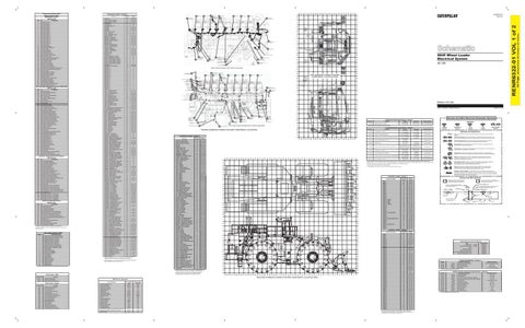
Machine locations such as "A-11, N-11" refer to the MACHINE OR CAB HARNESS CONNECTOR AND COMPONENT LOCATION GRID.
17
Module not responding.
18
Sensor supply fault.
19
Condition not met.
20
Parameter failures.
SWITCH - RH SERVICE BRAKE PEDAL
Machine locations such as "23" refer to the ENGINE HARNESS CONNECTOR AND COMPONENT LOCATIONS illustrations.
¹The FMI is a diagnostic code that indicates what type of failure has occurred.
E-11
C-33, S-33
SWITCH - RUNNING LAMP
H6
D-37, Q-37
SWITCH - STAIRWAY ACESS LAMP
E-6
D-37, Q-37
SWITCH - STEERING LOCK
J-12
E-35, V-35
SWITCH - STOP LAMP
F-11
C-33, U-33
SWITCH - THROTTLE LOCK RESUME
K-11
E-35, R-35
SWITCH - THROTTLE LOCK SET
K-11
E-35, R-35
SWITCH - THROTTLE LOCK ON-OFF
J-6
D-36Q-36
SWITCH - TORQUE CONVERTER LOCKUP
K-6
D-36, Q-36
SWITCH -REAR BRAKE ACCU PRESS
I-16
B-39, T-39
THERMOSTAT
J-18
T-40, C-40
Machine locations such as "A-11, N-11" refer to the MACHINE OR CAB HARNESS CONNECTOR AND COMPONENT LOCATION GRIDS. Machine locations such as "23" refer to the ENGINE HARNESS CONNECTOR AND COMPONENT LOCATIONS illustrations.
Event Codes - VIMS Condition
VIMS Service Operations Service Operations
Event Codes - Engine
E038
Low Engine Coolant Temperature
E072
Oil Level Low Mark
E073
Oil Filter Differential Pressure High
E074
Oil Filter Differential Pressure Very High
E095
Fuel Filter Restriction Warning
E098
Engine Prelube Override
E100
Low Engine Oil Pressure
E101
High Crankcase Pressure
E190
Engine Overspeed
E272
Inlet Air Restriction
E279
High Aftercooler Temperature
E540
Low Engine OilRefill Tank Level
E2089
Oil Renewal System Cannot Operate
V
U
U
T
T
S
S
R
R
Q
Q
P
P
O
O
Service Program Code
994F Wheel Loader Electrical System 442 1-295
N
CAB HARNESS CONNECTOR AND COMPONENT LOCATION GRID
16 INJECTOR 16
M
L
L
K
K
J
J
I
I
H
H
G
G
(ENGINE ECM)
24 FUSE BLOCK
19 JACKET WATER HEATER 2 (240 VAC)
21 ATMOSPHERIC PRESSURE SENSOR
FLYWHEEL HOUSING
F
F
E
E
Volume 1 of 2: Cab
STARTERS
Off Machine Switch Specification - Volume 1
D
D
61 CONNECTOR 58
Part No.
EMN GROUND
175-3244
C
C
LEFT SIDE VIEW OF ENGINE (RIGHT SIDE OF MACHINE)
Function Brake Accumulator - Pressure
B
Actuate
Deactuate
Contact Position
10700 kPa MAX (1552 psi) MAX
8960 ± 537 kPa (1300 ± 78 psi)
Pin A-B Normally Open² Pin A-C Normally Closed
Part No.
A 42
28
27
26
25
24
23
22
21
20
19
18
17
16
15
14
13
12
41
11
40
10
39
9
38
8
37
7
36
6
35
5
34
4
33
3
32
2
T
Function A/C Refrigerant - Pressure
1 X
Level Symbol
Circuit Breaker Symbol
Flow Symbol
Deactuate
Contact Position
170 ± 55 kPa (24.7 ± 8 psi)
Normally Open²
82.7 kPa MIN (12 psi) MIN
Normally Closed²
Fuse - A component in an electrical circuit that will open the circuit if too much current flows through it.
82.7 kPa MIN (12 psi) MIN
Normally Closed²
Switch (Normally Open): A switch that will close at a specified point (temp, press, etc.). The circle indicates that the component has screw terminals and a wire can be disconnected from it.
Fuel Filter - Differential Pressure
144-5661
Steering & Impl Oil Cooler Bypass - Differential Pressure
137.9 ± 13.8 kPa MAX (20 ± 2 psi) MAX
164-7577
Transmission Filter Bypass - Force
171-8708
Coolant - Flow
8.9 N MAX (2 lbs) MAX
Symbols And Definitions
Normally Open²
.362 ± .029 N³ (1.3 ± 0.1 oz)
.303 N MIN (1.09 oz) MIN
Normally Open²
Above deactuation pt. but at least 2.3 mm. (.09 in.) before contacting stop.
Fluid level to be 10 ± 5 mm. (.39 ± 0.2 in.) below centerline of Sw
Normally Open²
Switch (Normally Closed): A switch that will open at a specified point (temp, press, etc.). No circle indicates that the wire cannot be disconnected from the component. Ground (Wired): This indicates that the component is connected to a grounded wire. The grounded wire is fastened to the machine.
172-8660
Implement, Brake, Steering, Oil Recovery & VIMS - Level
174-4312
Parking Brake - Pressure
8270 kPa MAX (1200 psi) MAX
6890 ± 345 kPa (999 ± 50 psi)
Pin A-B Normally Open² Pin A-C Normally Closed
227-6744
Front Pump Drive Lube - Pressure
276 ± 28 kPa (40 ± 4 psi) MAX
179 MIN (26 psi) MIN
Normally Closed²
253-2673
Case Drain Bypass & Pilot Filter Bypass - Differential Press
137.9 ± 28 kPa MAX (20 ± 4 psi) MAX
69 kPa MIN (10 psi) MIN
Normally Closed²
1200 kPa MAX (174 psi) MAX
700 ± 100 kPa (102 ± 14.5 psi)
Pin A-B Normally Open² Pin A-C Normally Closed
Primary Steering - Pressure
Temperature Symbol
Actuate
116-9933
3E-6450
Pressure Symbol
275 kPa MAX¹ (39.9 psi) MAX 137.9 ± 13.8 kPa MAX (20 ± 2 psi) MAX
31
X
Symbols
² Contact position at the contacts of the harness connector.
B
Printed in U.S.A.
Harness And Wire Electrical Schematic Symbols
60 ELECTRIC
Ground (Case): This indicates that the component does not have a wire connected to ground. It is grounded by being fastened to the machine. Reed Switch: A switch whose contacts are controlled by a magnet. A magnet closes the contacts of a normally open reed switch; it opens the contacts of a normally closed reed switch. Sender: A component that is used with a temperature or pressure gauge. The sender measures the temperature or pressure. Its resistance changes to give an indication to the gauge of the temperature or pressure.
T
¹ With increasing pressure the closed condition can be maintained up to 2800 ± 140 kpa (406 ± 20 psi), with decreasing pressure the closed condition can be maintained down to 170 ± 55 kpa (24.7 ± 8 psi). If 2800 kPa is exceeded, the contact will open & remain open until the pressure falls to 1750 ± 200 kPa (254 ± 29 psi). The contact will now close and remain closed until the pressure falls below 170 ± 55 kPa (24.7 ±8 psi).
Relay (Magnetic Switch): A relay is an electrical component that is activated by electricity. It has a coil that makes an electromagnet when current flows through it. The electromagnet can open or close the switch part of the relay.
² Contact position at the contacts of the harness connector.
Solenoid: A solenoid is an electrical component that is activated by electricity. It has a coil that makes an electromagnet when current flows through it. The electromagnet can open or close a valve or move a piece of metal that can do work.
³ With weight applied to the screw on lever arm which is nearest to the switch housing.
W
W
V
V
U
U
MAGNETIC LATCH SOLENOID - A magnetic latch solenoid is an electrical component that is activated by electricity and held latched by a permanent magnet. It has two coils (latch and unlatch) that make electromagnet when current flows through them. It also has an internal switch that places the latch coil circuit open at the time the coil latches.
Connector Location - Volume 1 Schematic Location
Machine Location
D-17
I-16, S-16
CONN 2
E-17
I-16, S-16
CONN 3
G-17
I-16, S-16
CONN 4
H-17
I-16, S-16
CONN 5
J-16
B-41, V-41
Connector Number
T
T
S
S
R
R
Q
Q
P
P
O
O
N
N
M
M
L
L
K
K
J
J
CONN 1
CONN 6
J-16
B-41, V-41
CONN 7
L-16
B-39, R-39
CONN 8
K-14
C-37, P37
CONN 9
I-14
D-37, P37
CONN 10
G-14
D-36, P36
CONN 11
F-14
C-35, P-35
CONN 12
C-14
F-41, Q-41
CONN 13
B-14
G-41, Q-41
CONN 14 - CAMERA
A-11
I-16, Q-16
CONN 15 - VIMS
C-11
E-33, T-33
CONN 16 - VIMS
C-10
D-33, T-33
CONN 17 - CAMERA
E-12
E-26, U-26
CONN 18
K-13
C-36, S-36
CONN 19
K-13
C-36, S-36
CONN 20
L-13
C-37, U-37
CONN 21
L-12
E-35, R-35
CONN 22
C-10
C-34, P-34
CONN 23 - 12V POWER PORT
G-7
D-37, Q-37
CONN 24
C-9
G-37, Q-37
CONN 25
B-9
G-37, Q-37
CONN 26
B-9
G-37, Q-37
CONN 27 - ENTERTAINMENT RADIO
A-5
J-38, R-38
CONN 28
B-7
D-35, P-35
CONN 29
C-7
D-35, P-35
CONN 30
C-7
D-38, P-38
CONN 31 - SERVICE TOOL
E-6
D-37, Q-37
CONN 32
I-3
G-40, Q-40
CONN 33
L-1
K-36, O-36
CONN 34
K-1
K-41, T-41
Harness And Wire Symbols 1 2
1 2
Deutsch connector: Typical representation of a Deutsch connector. The plug contains all sockets and the receptacle contains all pins.
Harness Identification Letter(s): (A, B, C, ..., AA, AB, AC, ...)
Wire, Cable, or Harness Assembly Identification: Includes Harness Identification Letters and Harness Connector Serialization Codes
Harness Connector Serialization Code: The "C" stands for "Connector" and the number indicates which connector in the harness. (C1, C2, C3, .....)
Part Number for Connector Plug
C-C4 AG-C3 130-6795 130-6795
Sure-Seal connector: Typical representation of a Sure-Seal connector. The plug and receptacle contain both pins and sockets.
L-C12 3E-5179
AG-C4 111-7898
Part Number For Connector Recepticle
1
325-AG135 PK-14
5A
Socket
Pin
Fuse (5 Amps)
Receptacle Pin or Socket Number
Single Wire Connector
9X-1123
Component Part Number
Plug
200-L32 BK-14
2
Harness identification code: This example indicates wire 135 in harness "AG".
Ground Connection
Circuit Identification Number
Wire Gauge
Wire Color
Connector Location - Volume 2
I
I
H
H
G
G
F
F
E
E
D
D
C
C
B
B
A
A 28
27
26
25
24
23
22
21
20
19
18
17
16
15
14
13
12
11
10
9
MACHINE HARNESS CONNECTOR AND COMPONENT LOCATION GRID
Transmission Abuse Event
Loss of Coolant Flow
V
Component Location - Volume 1
I-38, W-38
E035
W
A
B-5
High Exhaust Temperature
W
114-5333
LAMP - DOME
High Engine Coolant Temperature
14 INJECTOR 14
ENGINE HARNESS CONNECTOR AND COMPONENT LOCATIONS
G-33, T-33
E021
X
Off Machine Switch Specification - Volume 2
D-37, Q-37
E017
12 INJECTOR 12
(240 VAC)
G-7
Condition
X
M
BLOCK (240 VAC)
H-11
Event Code
10 INJECTOR 10
23 TERMINAL
KEYPAD - VIMS
Coasting in Neutral Warning
INJECTOR 8
59
DISPLAY - SPEED, TACH
“Machine Driven with Park Brake On”
8
20 ADEM CONTROL JACKET WATER HEATER 4 (240 VAC)
RELAY - PLATFORM FLOOD
Y
N
INJECTOR 6
RESISTOR
29
E627-3
6
22 CAN DATA LINK
D-25, S-25 H-16, V-16
Y
© 2011 Caterpillar, All Rights Reserved
25
E049-2
INJECTOR 4
32
CONNECTOR 44
H-16, V-16 H-16, V-16
Z
33
G-8 K-8
Z
SENSOR
K-14
H-8
RENR6322-01 May 2011
18 MAGNETIC TACH
RELAY - ENGINE SHUTDOWN RELAY - HVAC PRECLEANER
31
34
H-18
E047-1
4
SPEED/TIMING SENSOR
H-18
Event Code
INJECTOR 2
17 PRIMARY CAM
SENSOR - OIL PRESSURE -FILTERED
2
49
(EFPP) SWITCH
RELAY - ENGINE PRELUBE SECONDARY RELAY - FND FLOOD
32
48 THERMOSTAT SWITCH
37
FUEL FILTER DIFF PRESS SWITCH
H-28, P-28
LAMP - RH TOWER FLOOD 2
33
38
ROCKFORD FAN SOLENOID
I-10, V-10
34
50
39
TURBO OUTLET PRESSURE SENSOR
C-4
27
HEATER 3 (240 VAC)
INLET EXHAUST TEMP SENSOR
LAMP - LH TOWER FLOOD 2
J-17
47 JACKET WATER
42 LH TURBO COOLANT TEMPERATURE SENSOR
I-10, V-10
35
46 COOLANT FLOW SW 51
41 ELECTRONIC FUEL PRIMING PUMP
40
SENSOR - OIL PRESSURE - UNFILTERED
Failure Description
OIL RENEWAL VALVE (ATTACHMENT)
ENGINE OIL HEATER 1 (240 VAC)
Limit Switch (Parking Brake)
FMI No.
CRANKCASE PRESSURE SENSOR
53 CONNECTOR 46
2
C-4
36
45 ALTERNATOR 2
LH TURBO INLET PRESSURE SENSOR
LAMP - LH TOWER FLOOD 1
37
COMPRESSOR CLUTCH
Sensor (Supply Voltage)
Failure Mode Identifiers (FMI)¹
43 RH TURBO
44 A/C
0070
Component
INJECTOR 7
RIGHT SIDE OF ENGINE (LEFT SIDE OF MACHINE)
9
38
INLET PRESSURE
0041
CID
7
39
1 INJECTOR 1
(240 VAC)
8
F-11
3 INJECTOR 3
INJECTOR 5
TEMP SENSOR
ELECTRRONIC FUEL PRIMING PUMP (EFPP)
F-18
SENSOR - TRANS SPEED 2
5
INJECTOR 9
54 CONNECTOR 45
F-17
SENSOR - IMPLEMENT TANK OIL TEMP
9
58 RH TURBO
56 TIMING CAL PLUG
INJECTOR - 9
SENSOR - LH TURBO IN EXHAUST TEMP
Component
13 INJECTOR 13
57 AFTERCOOLER
FLYWHEEL HOUSING
INJECTOR - 8
SENSOR - IMPLEMENT PUMP PRESS
Electronic Transmission Control System (MID No. 081)
15 INJECTOR 15
40
8
7
6
5
4
3
2
1
Connector Number
Schematic Location
Machine Location
CONN 1
A-1
I-16, S-16
CONN 2
C-1
I-16, S-16
CONN 3
D-1
I-16, S-16
CONN 4
E-1
I-16, S-16
CONN 36
A-17
E-20, R-20
CONN 37
A-17
E-20, R-20
CONN 38
A-17
E-24, Q-24
CONN 39
B-17
H-16, N-16
CONN 40
G-18
36
CONN 41
L-18
C-24, W-24
Engine
CONN 42
L-16
E-26, T-26
Starting and Charging:
SENR2947
CONN 43
K-16
E-26, T-26
Hydraulic/Implement System:
RENR6323
Vital Information Management System (VIMS)
RENR6318
Power Train/Transmission Control:
RENR6306
Related Electrical Service Manuals Title
Form Number
HDB Alternator: 50MT Electric Starting Motor:
177-9953
SENR4130
6V-0889
SENR3860 RENR9347
CONN 44
I-17
31
CONN 45
H-15
H-20, T-20
CONN 46
G-15
H-20, T-20
CONN 47
B-16
I-20, Q-20
CONN 48
A-16
H-20, Q-20
CONN 49
A-15
I-20, Q-20
CONN 50
B-13
H-20, T-20
CONN 51
B-13
H-20, T-20
Part No.
CONN 52
D-13
F-20, T-20
111-0879
Resistor:
CONN 53
E-14
H-18, T-18
174-3016
Resistor 1:
CAN Termination Resistor
CONN 54
F-13
H-16, S-16
239-9368
Resistor 3:
HVAC Water Valve Resistor
CONN 55
J-14
E-26, W-26
9G-1950
Resistor:
CONN 56
L-14
E-25, T-25
¹ At room temperature unless otherwise noted.
CONN 57
E-11
G-16, S-16
CONN 58
D-12
61
CONN 59
B-10
G16, R-16
Part No.
CONN 60
B-10
G-16, S-16
134-2540
Resistor:
Can Data Link Resistor 2
CONN 61
B-9
G-14, R-14
143-5122
Resistor:
Fan Speed Resistor 1
CONN 62
C-10
G-16, S-16
147-5399
Solenoid:
CL1, CL2, CL3, CL4 & CL5 Transmission Solenoids
8.1 - 8.22
CONN 63
C-9
G-14, R-14
152-8385
Solenoid:
Implement Raise Stop & Lower Kickout Cushion Solenoids
31.0 - 34.2
Resistor Specifications - Volume 1 Component Description
Resistance (Ohms)¹
Water Valve Temp Select Rheostat
4500 - 5500 @ Maximum setting
Blower Resistor
108 - 132 26730 - 27270 .95 - 1.05 on each side of tap
Resistor, Sender and Solenoid Specifications - Volume 2 Component Description
CONN 64
E-9
H-18, V-18
153-0509
Sender:
Service Program CodeNumber
CONN 65
F-9
H-18, V-18
185-0008
Solenoid:
CONN 66
C-8
H-13, S-13
196-1185
Sender:
Fuel Level Sender LH & RH Air Horn Valves Transmission Speed Sensors
Resistance (Ohms)¹ 108 - 132 3135 - 3465
92 -98 Empty, 0-3.5 Full 72 - 76 1000 - 1200
Show Acknowledged Events
"EACK"
3225
CONN 67
A-8
G-14, Q-14
216-5342
Solenoid:
Lockup Clutch Solenoid
8.3 - 9.1
Show Event Statistics
"ESTAT"
37828
CONN 68
A-8
F-12, Q-12
217-2708
Solenoid:
Impeller Clutch Solenoid
6.75 - 8.75
Show Event List Contents.
"ELIST"
35478
CONN 69
A-6
E-11, S-11
217-4448
Solenoid:
A/C Clutch Solenoid
Toggle Display Language
"LA"
52
CONN 70
A-6
G-12, R-12
235-0266
Toggle Display Units
"UN"
86
CONN 71
C-6
G-13, P-13
235-8824
Machine Status
“MSTAT”
67828
CONN 72
C-5
H-11, P-11
¹ At room temperature unless otherwise noted.
Start/Stop Data Logger
“DLOG”
3564
CONN 73
C-6
G-13, U-13
Calibrate Payload Monitor
“PAYCAL”
729225
CONN 74
C-5
H-11, U-11
Reset Service Lamp
“SVCLIT”
782548
CONN 75
K-3
H-16, V-16
Self Test
“TEST”
8378
CONN 76
J-3
H-16, V-16
Payload ResettableTotals
“TOT”
868
CONN 77
I-3
H-16, V-16 H-16, V-16
Start Event Recorder
“EREC”
3732
CONN 78
H-3
Reset Data Logger
“DLRES”
35737
CONN 79
G-3
H-16, V-16
Backlight Intensity
“BLT”
258
CONN 80
F-3
H-16, V-16
Message Center Contrast
“CON”
266
CONN 81
E-3
H-16, V-16
Odometer Set/Reset
“ODO”
636
CONN 82
B-4
H-16, W-16
“RESET”
73738
CONN 83
B-3
I-16, U-16
CONN 84
A-3
H-16, S-16
Clear Resettable Totals Set Service Light Options (This command can be performed when the PC for VIMS is connected to the machine.) Set Event Trigger
“SVCSET”
782738
“ERSET”
37738
The connectors shown in this chart are for harness to harness connectors. Connectors that join a harness to a component are generally located at or near the component. See the Component Location Chart.
Solenoid: Solenoid:
Oil Renewal Valve Ether 1 & Ether 2 Valves
13.4 86.6 31 - 46 at 93C
(Dimensions: 56 inches x 35 inches)
AIR DRYER
Schematic Location
41
42 Page,
Component
11 INJECTOR 11
RENR6322-01 VOL 1 of 2
Component Identifiers (CID¹) Module Identifier (MID²) ADEM Engine Control (MID No. 036)