Component Location Schematic Location
Machine Location
Alarm - Action
E-4
C
Alarm - Backup
C-12
1
Alternator
B-11
Batteries Batteries
MID No. 26 81
Module
Computerized Monitoring System (CMS) Autoshift Transmission Control
CID No.
Component
Computerized Monitoring System (CMS)
096 100 110 168 177 248 270 271 324 600 601 627 168 190 248 362 368 617 621 627 631 632 633 634 635 636 650 668 671 680 685 687 688
Fuel Level Sensor Engine Oil Pressure Sensor Engine Coolant Temperature Sensor Electrical System Voltage Power Train Oil Temperature Sensor Data link Harness Code Action Alarm Action Lamp Hydraulic Oil Temperature Sensor Brake Air Pressure Sensor Parking Brake Switch Electrical System Voltage Engine RPM Sensor CAT Data Link Ride Control Solenoid Auto/Manual Switch Air Inlet Heater Relay Downshift Switch Parking Brake Switch Solenoid 1 (reverse) Solenoid 2 (forward) Solenoid 3 (speed 4) Solenoid 4 (speed 3) Solenoid 5 (speed 2) Solenoid 6 (speed 1) Harness Code Shift Handle Transmission Speed Sensor Ride Control Switch Service Identification Code Options Identification Code Dual Horsepower Solenoid
Wire Color
Sensor - Engine Speed
D-11
14
101
RD
BAT
A401
YL
Sensor - Hydraulic Temp (CMS)
A-2
15
102
BU
HD LMP
A475
PU
2
Sensor - Lift Cyl Press
B-1
16
103
YL
AUX CKT
B412
YL
OPR MON PANEL SECONDARY BRK PRESS (TUV ONLY) WTL PMS LIFT POS SENSOR
B-11
3
Sensor - Lift Position
B-2
17
104
YL
AUX CKT
B413
PU
WTL PMS LIFT CYL PRESS. SENSOR
E-12
4
Sensor - Trans Oil Temp (CMS)
D-11
13
105
BR
KEY SW
B414
OR
WTL PMS NORM/CALIBRATE OUT
Breaker - Alternator
F-12
D
Sensor - Trans Output Speed
B-1
18
108
BU
AUX CKT
B415
PK
WTL PMS CLEAR / CHG OUT
109
OR
ALT OUTPUT (+) TERM.
B416
WH
WTL PMS REWEIGH SW IN
Breaker - Blower Motors
C-5
E
Solenoid - A/C Clutch
C-10
19
112
PU
MAIN POWER RELAY OUTPUT
B417
YL
WTL PMS STORE SW IN
Breaker - Engine Shutdown
F-12
D
Solenoid - Bucket Float
B-5
E
113
OR
OPR MON PANEL VMIS B+ SWITCHED
Breaker - Main
F-12
D
Solenoid - Bucket Kickout
B-5
E
114
GN
WARNING HORN (FORWARD)
500
BR
WIPER - FRONT (PARK)
Breaker - Running Lamp
F-12
D
7
BR
AUX CKT
501
GN
WIPER - FRONT (LO)
Solenoid - Dual HP
C-11
116 118
GY
AUX CKT
502
OR
WIPER - FRONT (HI)
Buffer - Fuel Level
E-1
5
Solenoid - Dual Pump
A-8
8
120
YL
AUX CKT
503
BR
WIPER - REAR (PARK)
Control - Autoshift
E-8
6
Solenoid - Engine Shutdown
C-11
7
121
YL
BACKUP ALARM TO LAMP
504
YL
WIPER - REAR (LO)
Control - Engine Shutdown
F-10
F
Solenoid - Lift Kickout
B-4
E
124
GN
A/C
505
BU
WIPER - REAR (HI)
126
PK
XMSN CONT
506
PU
WASHER - FRONT
Control - Payload Monitor
C-3
E
Solenoid - Ride Control
B-2
16
127
OR
AUX CKT
507
WH
WASHER - REAR
Control - Shifter
E-3
A
Solenoid - Start Aid
A-10
F
128
PK
AUX CKT
508
PU
RADIO SPEAKER - LEFT
Converter - Voltage
F-4
A
Solenoids - Transmission
E-10, F-10
20
129
BU
AUX CKT
509
WH
RADIO SPEAKER LEFT (COMMON)
A-11
F
26
GN
AUX CKT
511
BR
RADIO SPEAKER - RIGHT
Switch - Blower
F-7
130 135
BU
AUX CKT
512
GN
RADIO SPEAKER - RIGHT (COMMON)
Fuses
B-5, C-5
E
Switches - Brake Oil (CMS)
F-1
5
138
GN
AUTO LUBE PUMP TO PAYLOAD MON
513
OR
A/C COMPRESSOR/REFRIGERANT PRESS. SW
Fuses
F-12
D
Switch - Bucket Positioner
B-1
21
144
GN
AUX CKT
515
GY
BLOWER MOTOR (HI)
Ground - Starter To Frame
B-11
7
Switch - Disconnect
B-11
7
164
WH
HYDRO CONT TO WTL POWERTRAIN CTRL
516
GN
BLOWER MOTOR (MEDIUM)
177
OR
MAIN BKR
517
BU
BLOWER MOTOR (LO)
Ground - Platform To Frame
A-7
8
Switch - Dual Pump
B-6
B
193
PU
AUX CKT
521
YL
A/C SW TO REFRIGERANT SW
Lamp - Action (CMS)
A-3
B
Switch - Engine Oil Press (CMS)
D-12
13
522
WH
A/C CLUTCH TO THERMOSTAT SW
Meter - Service
E-7
26
Switch - Flood Lamp
E-6
C
200
BK
MAIN CHASSIS
537
GN
TURN SIGNAL SW TO FLASHER
Monitor - Operator (CMS)
E-4
B
B
BK
OPR MON PANEL CMS
538
BR
HAZARD INDICATOR
Switch - Front Wiper
F-3
201 202
BK
XMSN CONT
Monitor - Payload (Display)
C-2
B
Switch - Hydraulic Oil Level (CMS)
A-2
15
203
BK
CHASSIS DIAGNOSTIC
603
PK
ROTARY BEACON
Motor - Blower
D-9
9
Switch - Key Start
D-5
C
206
BK
BAT SIDE OF DISCONNECT
604
OR
STOP LAMP
Motor - Blower
E-9
10
Switch - Lift Positioner
A-1
22
207
BK
STARTER DIAGNOSTIC
605
YL
TURN LAMP - LEFT
228
BK
FUEL LEVEL SENDER
606
GY
TURN LAMP - RIGHT
Motor - Front Washer
A-10
F
Switch - Parking Brake Press
E-1
12
250
BK
PAYLOAD MON - CUSTOMER GROUND
608
GN
FLOOD LAMP - REAR
251
BK
PAYLOAD MON - SYSTEM GROUND
610
OR
HEAD LAMP BASIC
270
BK
CMS IDENT CODE 0
611
PU
HEAD LAMP HI
271
BK
CMS IDENT CODE 1
614
PU
PARK/TAIL/DASH LAMP
272
BK
CMS DENT CODE 2
615
YL
CAB FLOOD LAMP/ROPS
273
BK
CMS DENT CODE 3
617
BR
TAIL/POSITION LAMP - LEFT (ROAD PKG)/WIDTH
274
BK
CMS DENT CODE 4
619
GN
HEAD LAMP LO
275
BK
CMS IDENT CODE 5
276
BK
XMSN CONT IDENT CODE 0
710
GN
XMSN SPEED PICKUP SIGNAL
Motor - Front Wiper
Electronic Transmission Control
Wire Number
Machine Location
Dryer - Brake Air
Component Identifiers (CID) List
Wire Color
Schematic Location
Component
Module Identifiers (MID)
Wire Description Wire Number
Component
F-3
B
Switch - Power Train Filter Press(CMS)
A-2
23
Motor - Rear Washer
A-10
F
Switch - Primary Steering Flow (CMS)
B-2
24
Motor - Rear Wiper
E-6
A
Switch - Rear Wiper
E-3
B
Motor - Starter
B-11
7
Switch - Refrigerant
C-11
15
Radio
Description
Ground Circuits
ELECTRICAL SYSTEM NO.1 VOLTAGE
T
A
Switch - Running Lamp
D-6
C
7
Switch - Start Aid
D-6
C
Relay - Main
F-12
D
Switch - Start Aid Coolant Temp
E-11
25
277
BK
XMSN CONT IDENT CODE 1
720
PU
XMSN BRAKE SW
278
BK
XMSN CONT IDENT CODE 2
751
GN
XMSN SHIFT SOL NO. 1 OR 3
279
BK
XMSN CONT IDENT CODE 3
752
YL
XMSN SHIFT SOL NO. 2
280
BK
XMSN CONT IDENT CODE 4
754
BU
XMSN SHIFT SOL NO. 3 OR 1
F-12
0
Switch - Stop Lamp
E-1
12
Resistor - Blower Speed
D-9
11
Switch - Thermostat
E-7
26
Resistor - System Voltage (CMS)
F-11
D
Switch - Trans Auto/Manual
D-5
B
281
BK
XMSN CONT IDENT CODE 5
755
OR
XMSN SHIFT SOL NO. 4 OR 5
Resistor - Starting System Diagnostics
B-11
7
Switch - Trans Downshift
C-6
C
290
BK
SERVICE
761
GY
LIFT KICKOUT SOL SW
Sender - Fuel Level (CMS)
E-1
5
Switch - Trans Neutralizer Override
B-4
B
291
BK
CLEAR
762
YL
BUCKET POSITIONER SQL SW
Sensor - Brake Air Pressure (CMS)
E-1
12
Switch - Trans Neutralizer Press
D-3
12
292
BK
CMS US/METRIC UNITS
795
YL
DUAL HP SOL
A221
BK
TRANS CONTROL OPTIONS CODE 0
D743
GN
RIDE CONT - WTL IMPL CONT SW TO GND N/O
Sensor - Engine Coolant Temp (CMS)
E-1
13
A222
BK
TRANS CONTROL OPTIONS CODE 1
D744
WH
RIDE CONT - WTL IMPL CONT SW TO GND N/C
E701
PK
AUTO RIDE CONTROL SW
301
BU
STARTER NO. 1 SOL
E702
OR
AUTO RIDE CONTROL SW
302
OR
STARTER NO. 1 RESISTOR TO DIAGNOSTIC
818
BR
SERIAL DATA (TRANSMIT)
B = Components in dash.
304
WH
819
GY
SERIAL DATA (RECEIVE)
C = Components in right console.
306
GN
820
BU
TRANSMIT KEY
D = Components at relay panel.
307
OR
863
BU
PAYLOAD MON TRANSMIT LCD OUT
E = Components in service compartment - Rt. Side.
308
YL
STARTER RELAY NO. 1 OUTPUT STARTER RELAY COIL TO NEUT START SW OR KEY SW KEY SW TO NEUT START SW OR VMIS SENSOR MODULE MAIN POWER RELAY COIL
864
BR
PAYLOAD MON CLOCK LCD OUT
F = Components in compartment behind operators cab.
310
PU
START AID SW TO START AID SOL
865
GY
PAYLOAD MON LATCH LCD OUT
311
WH
START AID SOL TO TEMP SW
900
PU
XMSN SHIFT SQL NO. 5 OR 4
321
BR
BCKP ALARM LAMP TRAVEL ALARM
901
WN
XMSN SHIFT SQL NO. 6
322
GY
WARNING HORN (FORWARD)
910
YL
XMSN NEUTIZER OVERRIDE INDICATOR
326
PU
KEY SW “C" TERM.
921
WH
XMSN SOL NO 1 OR 3 RETURN
Monitoring Circuits
922
BR
XMSN SOL NO 2 RETURN
Failure Mode Identifiers (FMI) List Failure Description
0
Data valid but above normal operational range.
1
Data valid but below normal operational range.
2
Data erratic, intermittent, or incorrect.
3
Voltage above normal or shorted high.
4
Voltage below normal or shorted low.
5
Current below normal or open circuit.
6
Current above normal or grounded circuit.
7
Mechanical system not responding properly.
8
Abnormal frequency, pulse width, or period.
9
Abnormal update.
10
Abnormal rate of change.
11
Failure mode not identifiable.
12
Bad device or component.
13
Out of calibration.
10
6
26
7
1
2
13
D
403
GN
ALTERNATOR (R) TERM.
923
GY
XMSN SOL NO 3 OR 1 RETURN
405
GY
OPR MON OIL PRESS. (LO SETTING)
924
GN
XMSN SOL NO 4 OR 5 RETURN
409
OR
OPR MON NEUT
925
YL
XMSN SOL NO 5 OR 4 RETURN
410
WH
OPR MON ACTION ALARM
926
BU
XMSN SOL NO 6 RETURN
411
PK
OPR MON MASTER ACTION LAMP
944
OR
CMS COMM +
416
OR
SUPPL STER SW
945
BR
CMS COMM -
417
GY
PRIMARY STER SW
965
WH
TRANS SOL 1 SW TO GND
419
YL
OPR MON PARKING BRAKE
966
GY
TRANS SOL 3 SW TO GND
429
YL
OPR MON BRAKE OIL TEMP
968
BR
TRANS SOL 2 SW TO GND
432
PK
OPR MON BRAKE PRESS. (OIL)
969
YL
TRANS SOL 3 SW TO B+
433
BU
OPR MON BRAKE PRESS. (OIL) JUMPER
970
GN
TRANS SOL 4 SW TO GND
439
YL
LAMP INDICATOR
971
YL
TRANS SOL 5 SW TO GND
440
BR
AIR PRESS. GAGE
972
BU
TRANS SOL 6 SW TO GND
441
OR
ENG COOLANT TEMP GAGE
973
BR
CST AUTOSHIFT- AUTO/MANUAL SW 2
442
GY
HYD SYSTEM TEMP GAGE
974
Pu
CST AUTOSHIFT- SLOW MODE SW
443
YL
POWER TRAIN TEMP GAGE
975
WH
CST AUTOSHIFT- SOL RETURN
447
PK
FUEL LEVEL GAGE
976
OR
RIDE CONT SOL
450
YL
TACH SENDER (+)
977
YL
CST AUTOSHIFT- AUTO/MANUAL SW 1
469
GN
FUEL LEVEL SENDER B+
978
GN
CST AUTOSHIFT- SLOW MODE SW 1
496
WH
OPR MON PANEL HYD OIL LEVEL
B999
GN
TRANS SOL 1 SW TO B+ (LRT ONLY)
This indicates that the component has a wire connected to it that is connected to ground.
This indicates that the component does not have a wire connected to ground. It is grounded by being fastened to the machine.
19 2
7
A
11
1
25
24
B 11
6
C
E
9 3
5
3
F
Connector
16
26
19
13
14 25
6T-2217
Resistor - Monitor System Voltage (CMS)
150.0 ± 7.5
102-0347
Solenoid - A/C Clutch
14.4 ± 0.6
8C-9635
Solenoid - Bucket Float/Kickout
110.0 ± 6.0
Schematic Location
3E-6424
Solenoid - Dual HP Push Coil Pull Coil
24
1 3
7
7
20
23
4
18
11
8
5
8
5
Title
Alternator: (100-5047) Consist No. 100-5046 Consist No. 100-5045
SENR2082 SENR4130
Computerized Monitoring System (CMS)
SENR5247
Electronic Transmission Control
SENR5922
4.2 ± 0.42 16.1 ± 1.61
F-10
7T-2052
Solenoid - Dual Pump
110-6465
Solenoid - Engine Shutdown
5.12 ± 0.26
*
B - 117-2890 Computerized Monitoring System
E-4
B
B - 117-2890 L - 117-4677
C-3
8C-9634
Solenoid - Lift Kickout
110.0 ± 6.0
2
A - 118-3459 UU - 118-3460
D-11
B
B - 117-2890 JJ - 4E-8011
E-5
6T-5859
Solenoid - Ride Control
33.7 ± 1.0
D
A - 118-3459 Diagnostic Connector
E-12
*
FFF - 7I-3138 Payload Display
C-3
9G-4365
Solenoid - Start Aid
6.00
*
FFF - 71-31 38 Payload Monitor Ctrl
C-3
E
B - 117-2890 M - 116-9275
C-5
3E-3748
Solenoids - Transmission
8.50
14 Contacts
3
A - 118-3459 X - 104-6727
F-10
7
A- 118-3459 C-116-0720
E-12
12 Contacts
1
A - 118-3459 B - 117-2890
B-8
8
A - 118-3459 E-118-5240
A-6
4
A - 118-3459 F - 118-5239
F-6
8
A - 118-3459 VV - 4E-5629
A-6
B
B - 117-2890 GGG - 117-5996
D-7
C
B - 117-2890 P-122-0036
D-6
B
B - 117-2890 L - 117-4677
E-3
9
D - 4E-4466 VV - 4E-5629
A-3
B
B - 117-2890 P - 122-0036
D-6
10
G - 118-5252 YY - 118-5253
B-2
16
15
4
Starting And Charging Systems
SENR2947
Starting Motor: (6V-5539) Consist No. 6V-5540 Consist No. 6V-5582 Consist No. 106-8554
9 Contacts
SENR3536 SENR4975 SENR3581
7 Contacts
6 Contacts
A
5 Contacts
*
FFF - 7I-3138 Payload Display
C-2
B
B - 117-2890 CMS Service Mode Plug
E-5
B
B - 117-2890 Front Wiper Motor
F-3
11
B - 117-2890 Autoshift Options Plug
E-8
B- 117-2890 Transmission Shifter
D-3
5
E - 118-5240 G - 118-5252
A-2
6
R - 8R-9203 S - 8R-8117
F-7
B
B - 117-2890 Transmission Shifter
D-3
E
B - 117-2890 M - 116-9275
C-5
11
B - 117-2890 Autoshift Service Mode Plug
E-5
B
B - 117-2890 Q - 8R-6083
D-4
11
E - 115-5240 FFF - 7I-3138
B-3
E
B - 117-2890 R - 8R-9203
D-9
*
T - 8R-6082 Radio
F-6
8 Contacts
Machine locations are repeated for connector located close together. * = Connector is located at component. A = Connectors in operator compartment. B = Connectors located in dash. C = Connectors located in right console. D = Connectors located at relay panel. E = Connectors located in service compartment - Rt. Side. F = Connectors located in compartment behind operators cab.
4 Contacts
*
G - 118-5252 Rear Wiper Motor
E-6
AA
Typical representation of a Deutsch connector. The plug contains all sockets and the receptacle contains all pins.
Receptacle
Plug
1 2
1 2
1
2
Typical representation of a Sure-Seal connector. The plugand receptacle contain both pins and sockets.
Pin or Socket Number
41.90
Wire, Cable, or Harness Assembly Identification
Component Part Number
Single Wire Connector C
A
A 325-PK-14
Pin
¹ At room temperature unless otherwise noted.
B
2
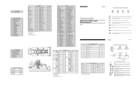
MACHINE HARNESS CONNECTOR AND COMPONENT LOCATIONS
Harness And/Or Components
A-3
10
Form Number
Machine Location
B - 117-2890 L-117-4677
17
Related Electrical Service Manuals
Connector
B
21
12
Schematic Location
E-8
10 Contacts
22
Harness And/Or Components
Autoshift Control B - 117-2890
B
6
1
3
2
E 9
150.0 ± 7.5
*
17
C
10 6
Resistor - Starter/Diagnostic Conn
F
A
9
6T-2217
Harness And Wire Electrical Schematic Symbols
Overall 2.0 ± .1; Tap 1.0 ± .05
B-8
40 Contacts
8
Machine Location
20 Contacts
F
Resistor - Blower Speed
1
21
25 Contacts
D
9G-1950
Resistance (Ohms)¹
A - 118-3459 Engine Shutdown Control
15
11
Component Description
A- 118-3459 B-117-2890
10
22
9
23
Resistor, Sender and Solenoid Specifications
Part No.
Connector Location
12
Printed in U.S.A.
© 1994 Caterpillar All Rights Reserved
8
4
18
20
14
The circle indicates that the component has screw terminals and a wire can be disconnected from it.
No circle indicates that the wire cannot be disconnected from the component.
5
FMI No.
Normally closed switch that is open due to an applied condition, and will close again with a specific decrease in that condition.
8JN1-UP
D04450
4
Normally closed switch that will open with an increase of a specific condition.
Control Circuits
Relay - Start
CID list applies to Monitor and Transmission Controls.
Normally open switch that is closed due to an applied condition, and will open again with a specific decrease in that condition.
980F Series II Wheel Loader Electrical System
F-6
Flow Symbol
Level Symbol
Normally open switch that will close with an increase of a specific condition (temp-press-etc.).
Lighting Circuits
Basic Machine Circuits
Temperature Symbol
Pressure Symbol
A-11
A = Components in operator compartment.
Electrical Schematic Symbols And Definitions
Accessory Circuits
Receptacle - Auxiliary Start
Machine locations are repeated for components located close together.
SENR6759 November 1994
Description Monitoring Circuits (Continued)
Power Circuits
AA 1
9X-1123 325-PK-14
Wire Color
Socket
2
200-BK-14
Circuit Number Identification
Wire Gauge
Electrical Schematic Symbols And Definitions
Part No.
Function
Off Machine Switch Specification
FUSE - A component in an electrical circuit that will open the circuit if too much current flows through it.
Actuate
Deactuate
Contact Position
5 kPa MIN (0.5 psi MIN)
Normally Open
2M-9346
Stoplamp Pressure
45 kPa MAX (6.5 psi MAX)
8N-1693
Engine Coolant Temperature (Start Aid)
37.8 ± 2.8°C (100 ± 5°F)
26.7°C MIN (80°F MIN)
Normally Closed
448 ± 35 kPa (65.0 ± 5.0 psi)
See Note ³
68.9 ± 20.8 kPa (10.0 ± 3.0 psi)
See Note ³
8T-9792
Parking Brake Pressure
517 ± 35 kPa (75.0 ± 5.0 psi)
9X-4276
Oil Pressure (CMS)
93.0 ± 20.8 kPa (14.0 ± 3.0 psi)
9X-7781
Power Train Filter Pressure (CMS)
210 ± 70 kPa (30 ± 10 psi)
9X-9418
Trans Neutralizer Pressure (Shifter)
103 ± 20 kPa (15.0 ± 3.0 psi)
69 kPa MIN (10.0 psi MIN)
Normally Closed
109-4215
Primary Steering Flow (CMS)
4 grams (.14 oz.)
1.5 grams (.05 oz)
Normally Open
114-5334
Refrigerant Pressure (AC)
275 to 1750 kPa ¹ (40 to 255 psi)
-
-
Normally Open
Normally Open ²
¹ A hysteresis band exists: with increasing pressure the closed condition can be maintained up to 2800 kPa (405 psi), with decreasing pressure the closed condition can be maintained down to 170 kPa (25psi). ² Contact postion at the contacts of the harness connector. ³ Contacts 1 - 3 Normally Closed; Contacts 1 - 2 Normally Open
REED SWITCH - A switch whose contacts are controlled by a magnet. A magnet closes the contacts of a normally open reed switch; it opens the contacts of a normally closed reed switch.
T
SENDER - A component that is used with a temperature or pressure gauge. The sender measures the temperature or pressure. Its resistance changes to give an indication to the gauge of the temperature or pressure. RELAY (Magnetic Switch) - A relay is an electrical component that is activated by electricity. It has a coil that makes an electromagnet when current flows through it. The electromagnet can open or close the switch part of the relay. CIRCUIT BREAKER (C/B) - A component in an electrical circuit that will open the circuit if too much current flows through it. This does not destroy the circuit breaker and it can be reset to become part of the circuit again. SOLENOID - A solenoid is an electrical component that is activated by electricity. It has a coil that makes an electromagnet when current flows through it. The electromagnet can open or close a valve or move a piece of metal that can do work. MAGNETIC LATCH SOLENOID - A magnetic latch solenoid is an electrical component that is activated by electricity and held latch by a permanent magnet. It has two coils (latch and unlatch) that make electromagnet when current flows through them. It also has an internal switch that places the latch coil circuit open at the time the coil latches.