101
RD
102
RD
Wire Color
12V, Battery (LH)
G-14
N-15,C-15
Battery (+)
A704
GN
Injector #4
12V, Battery (RH)
G-13
K-15, C-15
Floodlamp
A705
BU
Injector #5
Alarm, Action
D-2
L-10, F-10
Description Power Circuits
Description
Control Circuits (Continued)
Schematic Location
Component
Machine Location
Schematic Location
Machine Location
Sensor, Injection Actuation Pressure
E-15
E-13, N-13
Sensor, Injector Actuation Pressure
E-15
L-13, D-13
Sensor, Intake Air Temperature
D-15
L-13, D-13
Component
0096
Fuel Level Sender
105
RD
Key Switch
A706
GY
Injector #6
Alarm, Backup
I-13
M-15, C-15
Sensor, Lift Kickout
H-2
K-9, E-9
0100
Engine Oil Pressure Sensor
106
RD
MSS/Product Link
C744
PU
Parking Brake Solenoid
Alarm, Forward Horn
F-4
N-15, F-10
Sensor, Oil Temperature
E-15
L-13, D-13
0110
Engine Coolant Temperature Sensor
108
BU
Aux Ckt
E707
GN
VMIS Display +V
Alternator
F-15
N-14, D-14
Sensor, Override Pressure
F-13
M-12, E-12
0177
Torque Converter Oil Temperature Sensor
109
RD
Alt Output (+) Term.
E708
PK
VMIS Display Clock
Beacon
G-7
N-13, H-13
Sensor, Pilot Pressure, (LH)
E-12
M-12, E-12
0248
Data Link
110
RD
Aux. Power #2
E735
PU
Operator Mode Switch
0263
Sensor Power Supply
Coil, Ferrite
H-14
L-13, H-13
Sensor, Pilot Pressure, (RH)
E-12
M-12, E-12
111
RD
Aux. Power #1
F715
PU
Throttle Switch (Low Idle)
Coil, MSS
D-4
L-10, F-10
Sensor, Powertrain Oil Temperature
I-2
D-12, K-12
112
PU
Main Power Relay Output
F716
WH
Throttle Switch (Low Idle Parity)
Condensor, (LH)
E-9
H-13, N-13
Sensor, Speed Direction
G-8
N-12, F-13
113
OR
Operator Monitor Panel VMIS B+ Switch
F717
YL
Throttle Switch (High Idle)
Condensor, (RH)
D-9
H-13, K-13
Sensor, Speed Timing (A)
C-15
C-14, M-14
C-15
C-14, M-14
0271
Action Alarm
0280
Transmission Oil Temperature Sender
0324
Action Lamp
0600
Hydraulic Oil Temperature Sensor
114
RD
Warning Horn (Forward)
F718
BU
Throttle Switch (High Idle Parity)
Control, Drivetrain
A-10
K-13, E-13
Sensor, Speed Timing (B)
0819
Display Data Link
115
PK
Seat Suspension
F719
BR
Crank w/o Fuel Injector (N.C.)
Control, Engine
C-13
K-13, C-13
Sensor, Steering Pedal (LH)
B-4
M-10, E-10
0821
Display Power Supply
116
BR
Aux Ckt
F720
GN
Crank w/o Fuel Injector (N.O.)
Control, Machine Security System
H-15
L-13, F-13
Sensor, Steering Pedal (RH)
B-4
M-10, E-10
1045
Power Train Oil Temperature Sensor
117
YL
Aux Ckt
F762
GY
Ether Solenoid Drive From ECM
Control, Monitor
E-3
L-10, F-10
Sensor, Track Speed (LH)
I-4
M-12, C-12
1425
Implement Tank Oil Temperature Sensor
118
GY
Wipers
F780
PK
Parking Brake Switch
Control, Pilot Valve
A-6
K-12, F-12
Sensor, Track Speed (RH)
B-3
K-12, C-12
123
WH
Aux Ckt
H746
YL
Fan Control Solenoid Positive
Converter,12V / 24V
C-7
K-12, F-12
Sensor, Turbo Out Pressure
D-15
L-13, D-13
124
GN
Blower Switch
H747
BR
Fan Control Solenoid Return
Fuse Block
H-11
N-12, E-12
Solenoid, A/C Clutch
A-14
L-15, E-15
128
PK
Pilot Valve Control/Kickout Switch
M792
BU
Charge Filter Bypass Switch
Gage Cluster
F-3
L-10, F-10
Solenoid, Brake Valve
F-13
M-12, E-12
129
RD
12V Converter
N707
PU
Engine Digital Sensor Return
Heater, Inlet Air
F-15
N-14, E-14
Solenoid, Demand Fan
B-13
E-13, L-13
134
YL
Beacon
R746
PK
Turbo Outlet Pressure Sensor
Motor, Blower (LH)
D-10
M-14, F-13
Solenoid, Ether Aid
A-13
E-13, K-13
Engine Control Module (MID No. 036) CID
Component
0001
Injector Cylinder #1
0002
Injector Cylinder #2
0003
Injector Cylinder #3
0004
Injector Cylinder #4
0005
Injector Cylinder #5
0006
Injector Cylinder #6
143
BR
Beacon Switch
R747
GY
Atmospheric Pressure Sensor
Motor, Blower (RH)
C-10
L-14, F-13
Solenoid, Forward (LH)
G-13
M-12, E-12
150
RD
Engine Control
T725
WH
Fuel Filter Switch
Motor, Condensor #1
E-9
H-13, N-13
Solenoid, Forward (RH)
F-13
M-12, E-12
158
BR
A/C Condensor Relay
822
PK
Forward Hydrostatic Synchronized Solenoid
Motor, Condensor #2
D-9
H-13, N-13
Solenoid, Forward Hydrostatic Synchronize
F-13
M-12, E-12
0041
8V DC Supply Short to Battery
159
BU
Aux Ckt
828
WH
Hydrostatic Left Steering Pedal Sensor
Motor, Front Wiper
0042
Injector Acuation Valve
164
WH
Powertrain Control
829
GN
Hydrostatic Pedal Sensor
Motor, Fuel Priming Pump
0091
Incorrect Throttle Switch
0094
Fuel Pressure Sensor
0100
Engine Oil Pressure Sensor
0110
Engine Coolant Temperature Sensor
0164
Injector Actuation Pressure Sensor
0168
Electrical System Voltage
200 201
BK BK
F-6
M-9, H-10
A-13
D-9, K-9
Solenoid, IAP Control Valve
E-15
C-14, K-14
Solenoid, Injector 1-6
B-15
L-13, D-13
Ground Circuits
830
OR
Hydrostatic Right Steering Pedal Sensor
Motor, Precleaner
C-10
E-12, N-12
Solenoid, Override
G-13
M-12, E-12
Main Chassis
832
BR
Hydrostatic Right Motor Direction Sensor
Motor, Rear Wiper
G-6
M-13, F-13
Solenoid, Reverse (LH)
G-13
M-12, E-12
Operator Monitor Return
834
YL
Hydrostatic Left Motor Direction Sensor
Motor, Washer Pump (Front)
I-11
E-10, M-10
Solenoid, Reverse (RH)
F-13
BK
Powertrain Control
843
WH
Hydrostatic Left Pump Forward Solenoid
Motor, Washer Pump (Rear)
I-11
E-10, M-10
Starter, Motor
F-14
D-12, N-12
205
BK
MSS Control
844
GN
Hydrostatic Left Pump Reverse Solenoid
Port, 12V Power
B-7
K-12, F-12
Suppressor, Arc
A-14
L-15, E-15
C-8
D-13, K-13
Switch, A/C High/Low Pressure
A-14
L-15, E-15
0172
Intake Manifold Air Temperature Sensor
229
BK
Battery (-)
848
GY
Hydrostatic Speed Reverse Solenoid
Product Link
0190
Engine Speed Sensor
260
BK
Powertrain Control Ident Code 0
849
YL
Hydrostatic Right Pump Reverse Solenoid
Radio, 12V
G-2
M-12, H-12
Switch, Blower
C-9
K-12, F-12
0247
Data Link
261
BK
Powertrain Control Ident Code 1
850
PU
Hydrostatic Right Pump Forward Solenoid
Relay, Condensor #1
F-10
H-13, N-13
Switch, Charge Filter Bypass
B-13
L-13, D-13
0253
Personality Module
0261
Engine Timing Calibration
0262
5 Volt Sensor Power Supply
0264
Deceleration Throttle Position
262
BK
Powertrain Control Ident Code 2
851
WH
Hydrostatic Speed And Direction Sensor
Relay, Condensor #2
E-10
H-13, K-13
Switch, Clear
B-7
K-12, F-12
263
BK
Powertrain Control Ident Code 3
852
GN
Hydrostatic Charge Pressure Sensor
Relay, Inlet Air Heater
F-15
K-14, E-14
Switch, Differential Pressure
E-15
E-14, M-14
270
BK
CAT Monitoring System Ident Code 0
892
BR
CAT Data Link (-)
Relay, Main
G-12
N-12, E-12
Switch, Disconnect
G-13
K-14, D-14
271
BK
CAT Monitoring System Ident Code 1
893
GN
CAT Data Link (+)
Relay, Start
H-12
N-12, E-12
Switch, Forward Horn
G-8
N-12, F-13
D-10
F-13, K-13
Switch, Front Wiper
F-3
L-10, F-10
E-2
F-10, M-10
Switch, Fuel Priming Pump
A-13
L-13, D-13
Switch, Key
D-3
L-10, F-10
Switch, Lamp
F-2
L-10, F-10
D-2
L-10, F-10 N-12, F-13
0266
Crank Without Injection
0268
Programmed Parameter Fault
272
BK
CAT Monitoring System Ident Code 2
F846
PU
MSS LED
Resistor, Blower Motor
0274
Atmospheric Pressure Sensor
273
BK
CAT Monitoring System Ident Code 3
G826
BR
Filter Sensor (Power)
Resistor, Dimming
0291
Engine Cooling Fan Solenoid
274
BK
CAT Monitoring System Ident Code 4
G827
BU
Filter Sensor (Return)
Sender, Fuel Level
I-2
D-10, N-10
0296
Transm ission ECM
275
BK
CAT Monitoring System Ident Code 5
G828
WH
Pressure Sensor (Power)
Sender, Gearbox Oil Temperature
B-13
B-9, L-9
0342
Secondary Engine Speed Sensor
290
BK
CAT Monitoring System Service
G829
GN
Pressure Sensor (Return)
0544
Engine Cooling Fan Speed Sensor
Sensor, ATM Pressure
D-15
E-13, N-13
Switch, Operator
291
BK
CAT Monitoring System Clear
G833
PK
Temperature Sensor (Return)
1589
Turbo Inlet Air Pressure Sensor
Sensor, Brake Pedal
B-4
M-10, E-10
Switch, Parking Brake
H-8
G834
PU
Cooling Fan Speed (Power)
Sensor, Bucket Positioner
H-2
M-4, E-4
Switch, Rear Wiper
G-3
L-10, F-10
MSS LED
Sensor, Coolant Temperature
E-15
K-13, D-13
Switch, Rotating Beacon
E-2
L-10, F-10
1599
Engine Fan Pull Solenoid
1600
Engine Fan Push Solenoid
1639 1785
Basic Machine Circuits 304
WH
Starter Relay No. 1 Output
G848
GN
Machine Security System
306
GN
Starter Relay Coil
G849
BR
Engine Injector Actuation Pressure
Sensor, Engine Oil Pressure
D-15
L-13, C-13
Switch, Sensor Speed Calibration
B-7
K-12, F-12
Intake Manifold Pressure Sensor
307
OR
Key Switch
G854
PK
Injector Actuation Pressure Control Valve
Sensor, Engine Speed
A-14
K-13, D-13
Switch, Service
A-7
K-12, F-12
308
YL
Main Power Relay Coil
G855
PU
IAP Control Valve Common
Sensor, Fan Speed
C-13
E-13, L-13
Switch, Throttle
I-8
N-12, F-13
321
BR
Backup Alarm
G856
WH
TDC Probe +
Sensor, Fuel Pressure
D-15
K-13, D-13
Switch, Travel
H-8
N-12, F-13
Thermostat
D-10
L-13, F-13
Hydrostatic Transmission Control (MID 079) CID
Component
322
GY
Warning Horn (Forward)
G857
YL
TDC Probe -
Sensor, Hydraulic Oil Temperature
I-3
L-7, D-8
RD
Key Switch To Fuel Priming Pump
H832
YL
Pilot Pressure Sensor (LH)
Sensor, Implement Oil Temperature
H-2
C-7, L-7
Fuel Priming Pump To Fuel Priming Pump Sw
H835
GY
Pilot Pressure Sensor (RH)
0070
Rocker Switch (Parking Brake)
326
0132
Pressure Sensor (Override)
329
YL
0133
Solenoid (Override)
T858
GY
Injector High Side 1 & 2
0136
Pressure Sensor (Pilot) (Left Drive Motor)
403
GN
Alternator (R) Terminal
T859
WH
Injector High Side 3 & 4
0137
Pressure Sensor (Pilot) (Right Drive Motor)
0168
Electrical System
410
WH
Opr Mon Action Alarm
T860
OR
Injector High Side 5 & 6
0190
Engine Speed Sensor
411
PK
Opr Mon Action Lamp
975
WH
Powertrain Control Solenoid Return
0269
Sensor Power Supply
419
YL
Opr Mon Parking Brake
994
GY
Oil Pressure (Filtered)
0296
Hydrostatic Transmission Electronic Control Module
442
GY
Hydraulic Oil Temperature Gage
995
BU
Coolant Temperature Sensor
0349
Solenoid Valve (Synchronizing)
443
YL
Powertrain Temperature Gage
998
BR
Engine Digital Sensor Return
0466
Position Sensor (Left Pedal)
447
PK
Fuel Level Gage
C967
BU
Inlet Air Temperature
0467
Position Sensor (Right Pedal)
A485
BU
Opr Mon Implement Oil Temp
C976
YL
Parking Brake Switch
0468
Position Sensor (Center Pedal)
C413
YL
Vmis Display Data
C984
YL
Coolant Level Sensor
0469
Solenoid Valve (Left Forward Steering)
0470
Solenoid Valve (Left Reverse Steering)
C414
BU
Vmis Display Load
C991
PK
Fuel Filter Monitor
E417
OR
Park Brake Switch #2
E900
WH
Track Speed Sensor + (LH)
Monitoring Circuits
Solenoid Valve (Right Forward Steering) Solenoid Valve (Right Reverse Steering)
E901
GN
Track Speed Sensor - (LH)
0589
Switch (Travel Speed)
500
BR
Wiper - Front (Park)
E902
PU
Track Speed Sensor + (RH)
0650
Transmission Harness Code
501
GN
Wiper - Front (Low)
E903
YL
Track Speed Sensor - (RH)
0681
Solenoid Valve (Parking Brake)
502
OR
Wiper - Front (HI)
E963
BK
Engine Speed/Timing A (-)
0682
Lamp (Parking Brake)
503
BR
Wiper - Rear (Park)
E964
WH
Engine Speed/Timing A (+)
1868
Position Switch (Parking Brake/Speed Direction Lever)
Engine Speed/Timing B (-)
1869
Sensor (Speed Direction Lever)
² The MID is a diagnostic code that indicates which electronic control module diagnosed the fault.
Failure Mode Identifiers (FMI)¹ FMI No.
504
YL
Wiper - Rear (Low)
E965
BU
506
PU
Washer - Front
E966
YL
Engine Speed/Timing B (+)
507
WH
Washer - Rear
G939
PK
Powertrain Switch/Sensor Return
508
PU
Radio Speaker - Left
K972
BR
Start Relay
509
WH
Radio Speaker - Left (Commom)
K997
BU
+8V Power (Caterpillar Monitoring System)
15
Radio Speaker - Right
L912
WH
Engine Speed Sensor (+)
Radio Speaker - Right (Common)
L913
OR
Engine Speed Sensor (-)
513
OR
A/C Compressor/Refrigerant Pressure Switch
L983
WH
Injector Common 1 & 2
515
GY
Blower Motor (HI)
L984
OR
Injector Common 3 & 4
516
GN
Blower Motor (Medium)
L985
YL
Injector Common 5 & 6
517
BU
Blower Motor (Low)
N957
PK
Port 1 - RXD
521
YL
A/C Switch To Refrigerant Switch
N960
OR
Port 1 - TXD
CONN 5
B-11
E-13, K-13
522
WH
A/C Clutch To Thermostat Switch
N970
YL
Port 1 - DTR
CONN 6
D-12
D-11, M-11
592
BU
DC/DC Converter Power Output
N973
BR
Port 1 - DCD
CONN 7
D-12
D-11, M-11
A513
PK
DC/DC Converter Memory Output
N979
GN
Signal Gnd - Comm #1
CONN 8
E-12
D-11, M-11
C556
BU
Relay To Condensor Motor #1
R985
WH
Travel Speed Switch Travel Mode
CONN 9
F-12
E-12, M-12
C557
OR
Relay To Condensor Motor #2
R986
BU
Travel Speed Switch Work Mode
CONN 10
D-9
F-13, K-13
T901
YL
MSS Exciter Coil
CONN 11
E-9
H-14, L-14
CONN 12
H-10
E-12, N-12
CONN 13
E-8
D-11, K-11
E-8
D-11, K-11
Schematic Location
Machine Location
CONN 1
C-15
D-13, L-13
CONN 2
H-14
E-15, L-15
CONN 3
I-13
C-12, H-12
CONN 4
A-11
E-13, K-13
Connector Number
Data valid but above normal operational range.
600
BR
Dash Lamp
T902
PK
MSS Exciter Coil
1
Data valid but below normal operational range.
607
PK
Flood Lamp - Front
T951
YL
Injector #1 Hi-Side
2
Data erratic, intermittent, or incorrect.
CONN 14
610
OR
Head Lamp
T952
BR
Injector #2 Hi-Side
3
Voltage above normal or shorted high.
CONN 15
A-7
C-13, K-13
4
Voltage below normal or shorted low.
615
YL
Cab Flood Lamp/ROPS
T953
BU
Injector #3 Hi-Side
CONN 16 Service Tool Connector
B-7
F-12, L-12
5
Current below normal or open circuit.
663
GY
Gage Lamps - Smart EMS
T954
GY
Injector #4 Hi-Side
CONN 17
E-7, G-3
H-12, K-12
T955
GN
Injector #5 Hi-Side
CONN 18
D-4
F-10, L-10
T956
GY
Injector #6 Hi-Side
CONN 19
D-4
F-10, L-10
CONN 20
E-4
F-10, L-10
7
Mechanical system not responding properly.
761
GY
Lift Kickout Solenoid
8
Abnormal frequency, pulse width, or period.
762
YL
Bucket Positioner Solenoid
T957
PU
Injector #1 Return
9
Abnormal update.
799
WH
+8V Sensor Power
T958
YL
Injector #2 Return
10
Abnormal rate of change.
A700
OR
Digital Sensor Power
T959
BR
11
Failure mode not identifiable.
A701
GY
Injector #1
T960
12
Bad device or component.
13
Out of calibration.
A702
PU
Injector #2
T961
14
Parameter failures.
A703
BR
Injector #3
T962
WH
15
Parameter failures.
16
Parameter not available.
17
Module not responding.
18
Sensor supply fault.
19
Condition not met.
20
Parameter failures.
SENR3860
Transmission Electronic Control:
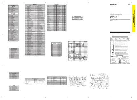
RENR8156
Caterpillar Monitoring System:
RENR2014
C-9 Engine Control:
RENR9345
LDX1-UP
Printed in U.S.A.
14
13
12
11
10
9
8
7
6
5
4
3
2
Temperature Symbol
1
CONN 21
E-4
F-10, L-10
CONN 22
H-4
D-10, N-10
Injector #3 Return
CONN 23
I-4
D-10, N-10
BU
Injector #4 Return
CONN 24
H-3
D-10, K-10
GN
Injector #5 Return
CONN 25
C-12
D-11, M-11
Injector #6 Return
CONN 26
C-12
D-11, M-11
CONN 27
C-12
D-11, M-11
Switch (Normally Open): A switch that will close at a specified point (temp, press, etc.). The circle indicates that the component has screw terminals and a wire can be disconnected from it.
N
Switch (Normally Closed): A switch that will open at a specified point (temp, press, etc.). No circle indicates that the wire cannot be disconnected from the component.
M
M
Ground (Wired): This indicates that the component is connected to a grounded wire. The grounded wire is fastened to the machine.
L
L
Ground (Case): This indicates that the component does not have a wire connected to ground. It is grounded by being fastened to the machine.
K
K
J
J
The connectors shown in this chart are for harness to harness connectors. Connectors that join a harness to a component are generally located at or near the component. See the Component Location Chart.
Reed Switch: A switch whose contacts are controlled by a magnet. A magnet closes the contacts of a normally open reed switch; it opens the contacts of a normally closed reed switch.
I
I
H
H
G
G
F
F
E
E
D
D
Relay (Magnetic Switch): A relay is an electrical component that is activated by electricity. It has a coil that makes an electromagnet when current flows through it. The electromagnet can open or close the switch part of the relay. Solenoid: A solenoid is an electrical component that is activated by electricity. It has a coil that makes an electromagnet when current flows through it. The electromagnet can open or close a valve or move a piece of metal that can do work. MAGNETIC LATCH SOLENOID - A magnetic latch solenoid is an electrical component that is activated by electricity and held latched by a permanent magnet. It has two coils (latch and unlatch) that make electromagnet when current flows through them. It also has an internal switch that places the latch coil circuit open at the time the coil latches.
Harness And Wire Symbols 1 2
C
C B
B
A
A
Sender: A component that is used with a temperature or pressure gauge. The sender measures the temperature or pressure. Its resistance changes to give an indication to the gauge of the temperature or pressure.
T
1 2
Deutsch connector: Typical representation of a Deutsch connector. The plug contains all sockets and the receptacle contains all pins.
Part Number for Connector Plug
C-C4 AG-C3 130-6795 130-6795
Harness Connector Serialization Code: The "C" stands for "Connector" and the number indicates which connector in the harness. (C1, C2, C3, .....)
14
13
12
11
10
9
8
7
6
5
4
3
2
1
Socket
Pin
L-C12 3E-5179
AG-C4 111-7898
Part Number For Connector Recepticle
1
325-AG135 PK-14
15
Sure-Seal connector: Typical representation of a Sure-Seal connector. The plug and receptacle contain both pins and sockets. Harness Identification Letter(s): (A, B, C, ..., AA, AB, AC, ...)
Wire, Cable, or Harness Assembly Identification: Includes Harness Identification Letters and Harness Connector Serialization Codes
¹The FMI is a diagnostic code that indicates what type of failure has occurred.
5A
Receptacle Pin or Socket Number
Single Wire Connector
9X-1123
Harness identification code: This example indicates wire 135 in harness "AG".
Event Codes Engine Control Module
Intake Manifold Air Temperature Sensor
Condition
E096
High Fuel Pressure Warning
E172
High Air Filter Restriction
E194
High Exhaust Temperature Warning
E198
Low Fuel Pressure Warning
E241
Abnormal Engine Fan System Operation
E360
Low Engine Oil Pressure Warning
E361
High Engine Coolant Temperature Warning
Part No.
E362
Engine Overspeed Warning
176-5321
Solenoid:
Demand Fan
2.2 ± 0.2
E539
High Intake Manifold Air Temperature Warning
106-5122
Solenoid:
17.6 ± 0.6
195-3739
Solenoid:
130-6913
Solenoid:
A/C Compressor Clutch Forward (LH) Reverse (LH) Forward (RH) Reverse (RH) Override Forward Hydrostat Synchronize
152-8385
Solenoid:
Brake Valve
32.6 ± 1.6
116-6203
Resistor:
Dimming
Engine Coolant Temperature Sensor Injector 1
Injector 2
Injector 4
Injector 3
Unit Injector Hydraulic Pump (IAPCV) integral to pump
Turbo Outlet Pressure Sensor
Atmospheric Pressure Sensor
Oil Grade Plug Engine Oil Temperature Sensor (End)
Air Inlet Heater Relay
Injector 5 Injector 6
Resistor, Sender and Solenoid Specifications Component Description
Off Machine Switch Specification Part No.
Function
114-5333
A/C (High / Low) Pressure
227-6744
Charge Filter Bypass Pressure
258-0883
Differential Pressure
Actuate
Deactuate
Contact Position
275 to 1750 kPa¹ (39.9 to 253.8 psi)
---
Normally Closed²
276 ± 28 kPa (40.0 ± 4.1 psi)
179 kPa MIN (26.0 psi MIN)
Normally Closed
110.3 ± 13.8 kPa (16.0 ± 2 psi)
69 kPa MIN (10 psi MIN)
Normally Closed
-1.1 ± 0.8°C (30 ± 1.4°F)
2.2 ± 0.8°C (36 ± 1.4°F)
Normally Closed
9G-1950
Resistor:
A/C, Heater Blower Motor
189-1522
Solenoid:
Pilot Control Valve
¹ With increasing pressure the closed condition can be maintained up to 2800 kpa (405 psi), with decreasing pressure the closed condition can be maintained down to 170 kpa (25psi).
4W-9972
Sender:
Pump Drive Gearbox Oil Temperature
² Contact postion at the contacts of the harness connector.
273-0112
Sender:
Fuel Level
3E-5464
Thermostat
Resistance (Ohms)¹
8.7 ± 0.4
32.6 ± 1.6 20 ± 1
Injector Harness Connector
Overall 2.0 ± 0.1 Tap 1.0 ± 0.05
Primary Engine Speed/Timing Sensor
65.9 ± 3.6 54°C (130°F) 560 to 716 110°C (230°F) 72 to 82 Empty - 92 ± 98 Full - 0 ± 3.5
¹ At room temperature unless otherwise noted.
Event Codes Hydrostatic Transmission Control Event Code
Condition
E283
Low Hydraulic Charge Pressure
E623
Low Left Track Forward Steering Pressure
E624
Low Left Track Reverse Steering Pressure
E625
Low Right Track Forward Steering Pressure
E626
Low Right Track Reverse Steering Pressure
E702
High Left Track Steering Pressure
E703
High Right Track Steering Pressure
MACHINE FRONT ENGINE TOP VIEW
Secondary Speed/Timing Sensor
Engine Oil Temperature Sensor (Middle) Injection Acutuation Pressure Sensor
ENGINE LEFT SIDE VIEW
Engine Oil Pressure Sensor
Engine Control Module (ECM)
Fuse (5 Amps) Component Part Number
Plug
Event Code
Circuit Breaker Symbol
Flow Symbol
Fuse - A component in an electrical circuit that will open the circuit if too much current flows through it.
O
N
Level Symbol
Symbols And Definitions
Connector Location
BR
Current above normal or grounded circuit.
SENR3581
6V-0512 (ATCH)
O
0
6
207-1560
Electric Starting Motor:
T
GN
Control Circuits
Electric Starting Motor:
Pressure Symbol
511
Lighting Circuits
SENR4130
Symbols
512
Failure Description
185-5294
Harness And Wire Electrical Schematic Symbols
0472
¹ The CID is a diagnostic code that indicates which circuit is faulty.
Form Number
Alternator:
© 2006 Caterpillar, All Rights Reserved
0471
Accessory Circuits
Title
M-12, E-12
202
973C Tier III Track Loader Electrical System
Related Electrical Service Manuals
200-L32 BK-14
2 Ground Connection
Circuit Identification Number
Wire Color
Wire Gauge
(Dimensions: 48 inches x 35 inches)
Component
Wire Color
RENR8177 February 2006
Component Location
Wire Number
RENR8177
CID
Wire Number
36 Page,
Wire Description Component Identifiers (CID¹) Module Identifier (MID²) Caterpillar Monitoring System (MID No. 030)