NOT SHOWN
76
23
Connector Number
CONN 16 237
39
81
20
24 101 31 56
COMPONENTS NOT SHOWN
155
106 156
28
4
120
11
50
58 9 33
57
8
32
COLD START BATTERIES
5
16 47
15 48 112
BEHIND PLATE 121 13
110
109
17 14
44
115
18
Schematic Location
Component
30
J-13
1
Sensor GP - Pressure (Brake Accumulator Oil)
D-2
Alarm AS - Backup
H-13
2
Sensor GP - Pressure (Crankcase Breather)
H-15
80
CONN 3
C-15
Alternator
B-10
3
Sensor Gp - Pressure (DPF Delta P)
D-13
237
CONN 4
D-15
Arc Suppressor -Starter Relay
C-8
4
Sensor GP - Pressure (DPF Inlet)
D-13
81
CONN 5
D-14
Bar - Buss A
B-8
5
Sensor GP - Pressure (Engine Oil)
H-15
82
CONN 6
E-15
Battery 1
C-10
6
Sensor GP - Pressure (Fuel Filter) (Aft)
F-13
83
CONN 7
E-15
Battery 2
C-10
7
Sensor GP - Pressure (Fuel Filter) (Fore)
F-13
84
CONN 8
E-15
Battery 3 ATCH
C-10
8
Sensor GP - Pressure (Fuel Rail)
I-15
85
CONN 9
F-15
Battery 4 ATCH
C-10
9
Sensor GP - Pressure (Hydraulic Pump)
E-8
86
CONN 10
G-13
Block AS - Junction
B-8
10
Sensor GP - Pressure (Intake Manifold)
G-15
87
CONN 11
G-12
Block AS - Junction (Battery)
C-10
11
Sensor GP - Pressure (Lift Cylinder) (Head End)
H-2
88
CONN 12
G-12
Camera GP - Rear (115°, Color) ATCH
G-13
12
Sensor GP - Pressure (Lift Cylinder) ATCH
F-1
89
CONN 13
G-12
Circuit Breaker AS - Engine Control
C-8
13
Sensor GP - Pressure (NOX Reduction System)
G-15
90
CONN 14
J-12
Circuit Breaker AS - Machine Control
C-8
14
Sensor GP - Pressure (Park Brake)
D-2
91
CONN 15
J-12
Circuit Breaker AS - Main
B-8
15
Sensor GP - Pressure (Secondary Steering)
E-8
92
CONN 16
C-11
Circuit Breaker AS - Starting Motor
C-8
16
Sensor GP - Pressure (Transmission Bypass) ATCH
G-9
93
CONN 17
B-10
Coil AS - ARD Fuel Pressure
E-13
17
Sensor GP - Pressure (NOX Reduction System Intake)
G-15
94
CONN 18
E-8
Coil AS - ARD Fuel Pressure #2 Cont Actuator
E-13
235
Sensor GP - Soot
F-12
95
CONN 19
E-8
Coil AS - Ignition (ARD)
E-13
18
Sensor GP - Speed (Engine Timing)
G-15
96 97
CONN 20
F-8
Compressor GP - Refrigerant
B-14
19
Sensor GP - Speed (Input)
J-9
CONN 21
G-8
Control GP - ARD Air Flow
F-12
20
Sensor GP - Speed (Output 1)
J-9
98
CONN 22
G-8
Control GP - Engine (J1 Connector)
B-16
21
Sensor GP - Speed (Output 2)
J-9
99
CONN 23
I-7
Control GP - Engine (J2 Connector)
J-14
22
Sensor GP - Temperature (Coolant)
G-15
100
CONN 24
I-7
Ground - ARD Head
E-13
23
Sensor GP - Temperature (DPF)
E-13
101
CONN 25
J-7
Ground - CEM
D-13
24
Sensor GP - Temperature (Front Axle Oil)
H-2
102
CONN 26
I-5
Ground - Engine 1
E-13
25
Sensor GP - Temperature (Torque Converter)
A-14
103
CONN 27
F-7
Ground - Engine 2
B-11
26
Solenoid - Fuel Pump (Aft)
H-15
104
CONN 28
B-5
Ground - Frame 1
B-10
27
Solenoid - Fuel Pump (Fore)
H-15
105
CONN 29
D-5
Ground - Frame 2
C-10
28
Spark Plug
D-13
106
CONN 30
G-2
Ground - Main Chassis
G-7
29
Starting Motor GP - Electric
B-10
107
CONN 31
G-2
Ground - Resistor AS 1
C-10
30
Switch AS - Engine Shutoff
I-13
108
CONN 32
J-2
Ground - Resistor AS 3
C-10
31
Switch AS - Fuel Filler
E-4
109
CONN 33
E-3
Ground - Resistor AS 4
E-9
32
Switch AS - Hood Tilt Actuator
I-13
110
CONN 34
H-3
Ground - Resistor AS 5
B-8
33
Switch AS - Hydraulic Filter Bypass
C-2
111
CONN 35
I-3
Ground - Resistor AS 6
D-8
34
Switch AS - Liquid Level (Low Coolant)
F-8
112
CONN 36
I-2
Ground - Secondary Steering Pump ATCH
D-8
35
Switch AS - Power Train Guard ATCH
J-13
113
CONN 37
J-2
Horn AS - High Tone
J-2
36
Switch AS - Pressure (Power Train Oil)
C-2
114
CONN 38
J-2
Horn AS - Low Tone
J-2
37
Switch GP - Disconnect
D-10
115
CONN 39
D-4
Injector 1-6
E-14
38
Switch GP - Pressure (A/C High/Low)
A-14
116
CONN 40
C-4
Module AS - Aftertreatment ID
F-13
39
Switch GP - Pressure (A/C Low)
A-14
117
CONN 55
A-9
Motor AS - Hood Tilt
I-13
40
Switch GP - Pressure (Autolube) ATCH
G-3
118
CONN 56
B-9
Pump AS - Washer (Front)
C-2
41
Switch GP - Secondary Steering Relay ATCH
E-8
119
CONN 57
B-9
Pump AS - Washer (Rear)
C-2
42
Switch GP - Starter Relay
C-8
120
CONN 58
B-9
Pump GP - Autolube Pump ATCH
G-9
43
Valve GP - Air Control (ARD Combustion)
F-13
121
CONN 59
B-9
Pump GP - Fuel Priming
E-4
44
Valve GP - Clutch 1 (Reverse)
I-9
122
CONN 60
B-9
Pump GP - Secondary Steering ATCH
D-8
45
Valve GP - Clutch 2 (Forward)
I-9
123
CONN 61
H-5
Pump GP - Variable Pitch Fan ATCH
J-13
46
Valve GP - Clutch 3 (Speed 4)
I-9
124
235 70
Receptacle AS - Auxiliary Start
D-10
47
Valve GP - Clutch 4 (Speed 3)
I-9
125
Relay AS - ARD Fuel Nozzle Heater
D-13
48
Valve GP - Clutch 5 (Speed 2)
I-9
126
Relay AS - Backup Lamps ATCH
E-10
50
Valve GP - Clutch 6 (Speed 1)
J-9
127
Relay AS - Hood Raise/Lower Control
I-13
50
Valve GP - Exhaust Gas (NOX Reduction System)
Resistor AS - CAN Data Link A
B-15
51
Valve GP - Fuel Priming
EXHAUST MODULE
HARNESS R
REAR CAB
ENGINE COMPARTMENT SHEILD
LEFT CHASSIS - UNDER LEFT CAB DOOR
128
E-4
129 130
Resistor AS - Engine CAN Data Link 1
G-15
52
Valve GP - Quick Coupler ATCH
I-2
F-12
53
Valve GP - Solenoid (Cold Start/Hydraulic Fan) ATCH
F-9
131
Resistor AS 1
C-10
54
Valve GP - Solenoid (Demand Speed Fan)
B-3
132
Resistor AS 2
B-11
55
Valve GP - Solenoid (Dump)
G-1
133
Resistor AS 3
C-10
56
Valve GP - Solenoid (Dump/Anti-Drift)
G-1
134
Resistor AS 4
E-9
57
Valve GP - Solenoid (Implement Pilot Supply)
G-1
135
Resistor AS 5
B-8
58
Valve GP - Solenoid (Implement Pump Torque Limit)
D-4
136 137
Resistor AS 6
D-8
59
Valve GP - Solenoid (Lower)
G-1
Sender AS - Fuel Level
H-13
60
Valve GP - Solenoid (Lower/Anti-Drift)
G-1
138
Sensor - Temperature (Rear Axle Oil)
G-12
61
Valve GP - Solenoid (NOX Reduction System)
H-14
139
Sensor AS - Position (Steering Valve Spool)
H-8
62
Valve GP - Solenoid (Park Brake)
C-3
140
Sensor AS - Temperature (Charge Air Cooler Outlet)
H-15
63
Valve GP - Solenoid (Prime Steering) (LH)
I-8
141
Sensor AS - Temperature (Fuel)
G-13
64
Valve GP - Solenoid (Prime Steering) (RH)
I-8
142 143
F-8
65
Valve GP - Solenoid (Rackback)
H-1
Sensor AS - Temperature (Inlet Air)
G-12
66
Valve GP - Solenoid (Raise)
G-1
144
Sensor AS - Temperature (NOX Reduction System)
G-14
67
Valve GP - Solenoid (Ride Control 1)
H-1
145
Sensor AS - Temperature (Torque Converter Oil)
10
G-15
Resistor AS - Engine CAN Data Link 2
Sensor AS - Temperature (Hydraulic Oil)
CONN 14
79
Actuator GP - Power Train Guard ATCH
77
6
Machine Location
B-15
53
7
Schematic Location
A-15
108
46
Component
CONN 2
54 236
Machine Location
CONN 1
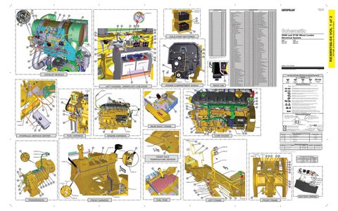
The connectors shown in this chart are for harness to harness connectors. Connectors that join a harness to a component are generally located at or near the component. See the Component Location Chart.
129
Schematic Location
J-9
68
Valve GP - Solenoid (Ride Control 2)
G-1
146
Sensor Gp - ARD Fuel Pressure #2 (Main)
E-13
236
Valve GP - Solenoid (Ride Control 3)
G-1
147
Sensor GP - Liquid Level (Oil)
C-14
69
Valve GP - Solenoid (Secondary Steering) (LH)
I-8
148
Sensor GP - Liquid Level (Water Separator)
E-4
70
Valve GP - Solenoid (Secondary Steering) (RH)
H-8
149
Sensor GP - Position (Lift)
F-2
71
Valve GP - Solenoid (Steering Pilot Supply)
I-8
150
Sensor GP - Position (Steering Cylinder) (LH)
F-7
72
Valve GP - Solenoid (Third Function/Port A) ATCH
F-1
151
Sensor GP - Position (Steering Cylinder) (RH)
F-9
73
Valve GP - Solenoid (Third Function/Port B) ATCH
F-1
152
Sensor GP - Position (Tilt)
I-2
74
Valve GP - Solenoid (Transmission Bypass) ATCH
G-9
153
Sensor GP - Pressure (Air Filter)
F-12
75
Valve GP - Start Aid
E-8
154
Sensor GP - Pressure (ARD Combustion Air)
D-13
76
Wire AS - Heater
E-14
155
Sensor GP - Pressure (ARD Pilot Fuel)
E-13
77
Wire AS - Ignition
E-13
156
Sensor GP - Pressure (Atmospheric Pressure)
H-15
78
966K and 972K Wheel Loader Electrical System 972K: PEM1-UP Z4W1-UP
966K: PBG1-UP TFS1-UP
Volume 1 of 2: Chassis © 2012 Caterpillar, All Rights Reserved
Printed in U.S.A.
Harness And Wire Electrical Schematic Symbols Symbols
T
Pressure Symbol
Temperature Symbol
Level Symbol
Circuit Breaker Symbol
Flow Symbol
Symbols and Definitions Fuse: A component in an electrical circuit that will open the circuit if too much current flows through it. Switch (Normally Open): A switch that will close at a specified point (temp, press, etc.). The circle indicates that the component has screw terminals and a wire can be disconnected from it.
100
CONN 5
CONN 9
Switch (Normally Closed): A switch that will open at a specified point (temp, press, etc.). No circle indicates that the wire cannot be disconnected from the component.
HARNESS EN 94
Ground (Wired): This indicates that the component is connected to a grounded wire. The grounded wire is fastened to the machine.
HARNESS AM
CONN 8 91
Ground (Case): This indicates that the component does not have a wire connected to ground. It is grounded by being fastened to the machine.
2
38
87
CONN 1
HARNESS FK
90
Reed Switch: A switch whose contacts are controlled by a magnet. A magnet closes the contacts of a normally open reed switch; it opens the contacts of a normally closed reed switch.
52
Sender: A component that is used with a temperature or pressure gauge. The sender measures the temperature or pressure. Its resistance changes to give an indication to the gauge of the temperature or pressure.
T
19
CONN 7 CONN 2
140
Relay (Magnetic Switch): A relay is an electrical component that is activated by electricity. It has a coil that makes an electromagnet when current flows through it. The electromagnet can open or close the switch part of the relay.
139
104 Solenoid: A solenoid is an electrical component that is activated by electricity. It has a coil that makes an electromagnet when current flows through it. The electromagnet can open or close a valve or move a piece of metal that can do work.
67 79
105
117
111 84
Magnetic Latch Solenoid: A magnetic latch solenoid is an electrical component that is activated by electricity and held latched by a permanent magnet. It has two coils (latch and unlatch) that make electromagnet when current flows through them. It also has an internal switch that places the latch coil circuit open at the time the coil latches.
40
Harness and Wire Symbols
64
CONN 3
114
Wire, Cable, or Harness Assembly Identification: Includes Harness Identification Letters and Harness Connector Serialization Codes (see sample).
96 116
CONN 40
L-C12 3E-5179
AG-C4 111-7898
103 132
Harness Identification Letter(s): (A, B, C, ..., AA, AB, AC, ...)
1
Part Number: for Connector Plug
Part Number: for Connector Receptacle
2
83 Plug
CONN 39
REAR RIGHT FRAME
CONN 6
42 69
CONN 4
51
Deutsch connector: Typical representation of a Deutsch connector. The plug contains all sockets and the receptacle contains all pins.
1 2
Sure-Seal connector: Typical representation of a Sure-Seal connector. The plug and receptacle contain both pins and sockets.
85 80
CONN 4
63
ENGINE HARNESS
FUEL HARNESS
1 2
5A Component Part Number
9X-1123
Fuse (5 Amps)
Harness identification code: This example indicates wire group 325, wire 135 in harness "AG".
Wire Gauge Wire Color
82
128
HARNESS FA
HYDRAULIC SERVICE CENTER
Receptacle Pin or Socket Number
325-AG135 PK-14
78 41
L-C12 3E-5179
Harness Connector Serialization Code: The "C" stands for "Connector" and the number indicates which connector in the harness (C1, C2, C3, ...).
21
Resistor, Sender and Solenoid Specifications
22
Part No.
CORE ENGINE
Component Description
134-2540
Resistor
240-7192
Resistor
175-4034
Sender
Resistance (Ohms)¹
CAN Data Link A
120 ± 10%
Engine CAN Data Link Resistor AS 1-6
1500 ± 5% Empty 240-250
Fuel Level
Full 28-33
Dump/Anti-Drift 328-4314
Solenoid
66
33.8
Lower/Anti-Drift Ride Control 1
75
Off-Machine Switch Specification 154
CONN 34 37
68
36
CONN 36
Part No.
CONN 28
71
65
HARNESS JC
CONN 23
Function
114-5333
A/C High/Low Pressure
149-6371
A/C Low Pressure
Actuate
Deactuate
275 to 1750 kPa¹
-
(39.9 to 253.8 psi)
-
103.4 ± 13.8 kPa
34.5 ± 7 kPa
14.9 ± 2.0 psi
5.0 ± 1 psi
Contact Position Normally Closed² Normally Open
¹ With increasing pressure the closed condition can be maintained up to 2800 kPa (405 psi), with decreasing pressure the closed condition can be maintained down to 170 kPa (25 psi).
CONN 29
² Contact position at the contacts of the harness connector.
102
CONN 24
CONN 31 CONN 30
FRONT AXLE TEMPERATURE SENSOR
CONN 25
HARNESS E 138
133
147
134
145
Related Electrical Service Manuals Title
Form Number
Cross Reference for Electrical Connectors:
HARNESS R
CONN 37
143
REHS0970
Alternator:
272-1889
SENR4130
Starting Motor:
350-8694
SENR3860
Engine Control:
KENR9796
146 89 95
149
137
HARNESS JA
60
CONN 33
148
151
97
29
CONN 57 CONN 56
142
HARNESS EK 123
135
CONN 19
122
HARNESS JY
124
144
119
CONN 18
125
150
CONN 55 CONN 59
126
152
127
CONN 27 HARNESS E
141
59
HARNESS HR
34 62 99
35
98
CONN 32 HARNESS EC
TRANSMISSION
CONN 26
CONN 38
FRONT HARNESS
45
FUEL TANK
92
LEFT FRAME
86
72
BATTERY WIRING
74
CONN 60
HARNESS EY
FRONT FRAME
(Dimensions: 56 inches x 35 inches)
CONN 58
RENR9766-04 VOL 1 of 2
25
RENR9766-04 August 2012
Component Location
42 Page,
Connector Location