UENR2527 January 2012 Wire Description
RD
102
RD
Wire Color
Bat (+)
G790
PK
Not Used
Hd Lmp
G791
BR
Not Used
Description
Component
Failure Mode Identifiers (FMI)¹ Failure Description
PU
Implement Control Reversing Fan Sw (N.O.)
YL
Implement Control Reversing Fan Sw (N.C.)
Arc Suppressor - Quick Coupler
J-2
4
Sensor - Rear Axle Oil Temp.
110
RD
Engine ECM
H704
PK
Auto Reverseing Fan Solenoid
Arc Suppressor - Secondary Steering
I-7
5
Sensor - Tilt Position
PU
Main Power Rly Output
H713
PK
Implement Control Lift Proportional Sol
Arc Suppressor - Start Relay
H-11
6
Sensor - Transmission Oil Temperature
H-7
26
Warning Horn (forward)
H714
OR
Implement Control Lower Proportional Sol
Batteries
J-10
7
Sensor - Transmission Input Speed
H-7
27
124
GN
Auto Lube Pump to Auto Lube Pressure Sw.
H717
BR
Implement Control Pilot Press Sol
Block Asm.
J-10
7
Sensor - Trans. Output Speed (Leading)
G-7
28
129
RD
Fuel Priming Pump to Machine Interface
H718
GY
Implement Control Tilt Cyl Position
Breaker - Alternator
G-12
6
Sensor - Trans. Output Speed (Trailing)
G-7
28
136
GN
Supplemental Steering
H746
YL
Variable Speed Fan Solenoid
138
GN
Auto Lube Pump To PCS
H747
BR
Variable Speed Fan Solenoid
Breaker - Belly Guard Actuator
I-12
6
Sensor - Turbo Inlet Pressure
F-10
29
141
RD
Beacon / Heated Mirrors
H795
PK
Engine Digital Sensor (Return)
Breaker - Hood Actuator
I-12
6
Solenoid - A/C Clutch
B-11
3
147
RD
ECAP / Center Dash Indicator Panel
J764
BR
Transmission Switch/Sensor Return #1
Breaker - Main
H-12
6
Solenoid - Aux Lift Prop
G-2
22
150
OR
Implement/Transmission/Engine ECM
K737
BR
Not Used
Breaker - Running Lamp
I-12
6
Solenoid - Aux Lower Prop
H-2
22
174
RD
Unswitched Bus Power
K738
GN
Not Used
Breaker - Start
175
RD
Hood Actuator
K739
BU
Not Used
Breaker - Unswitched Bus (Cab)
RD
Hood Actuator
N707
PU
Fuel Differential Pressure (Return)
Control - Engine
Ground Circuits
R746
PK
Atmosphereic Pressure Sensor (Ground)
Main Chassis
R747
GY
Boost Pressure Sensor Signal
BK
6
Solenoid - Lower Prop
H-3
22
CONN 6
D-12
8
Ground - LH
J-9
51
Solenoid - On / Off Pilot
G-2
22
CONN 7
E-13
8
Ground - RH
B-8
51
Solenoid - Quick Coupler
J-2
4
CONN 8
J-10
40
22
CONN 9
F-8
14
C-10
30
CONN 10
B-8
41
I-6
31
Engine ECM
Y795
GN
Expanded Can Data Link -
Motor - Autolube Pump
261
BK
Brake Oil Pressure Sw.
838
YL
Belly Guard Actuator
Motor - Belly Guard
C216
BK
Implement Return
839
BU
Belly Guard Actuator
Motor - Front Washer
B-5
9
Solenoid - Rack Back Prop
J-12
10
Solenoid - Reversing Fan
C-4&5
11
Solenoid - Start Aid
H-3
CONN 11
I-7
15
CONN 12
D-6
34
CONN 13
C-6
34
CONN 14
B-5
50 9
A893
OR
Fuel Priming Sw.
Motor - Fuel Priming Pump
B-10
12
Solenoid - Tilt Anti-Drift
H-3
22
304
WH
Starter Relay to Starter Motor
G828
WH
Engine +5V Sensor Supply
Motor - Hood Actuator
F-12
13
Solenoid - Variable Speed Fan
C-10
30
306
GN
Starter Relay Coil to Transmission Control
G829
GN
Engine Sensor Ground
Motor - Rear Washer
C-4&5
11
Solenoids - Cylinder Head ( 1 & 2)
F-14
21
CONN 15
C-5
308
YL
Main Power Relay Coil
G833
PK
Fuel Temperature Sensor (Ground)
321
BR
Backup Alarm Lamp Travel Alarm
G850
BU
Inlet Air Heater
322
GY
Warning Horn (Forward)
G856
WH
Timing/Cal. Probe (+)
326
PU
Key Sw 'C' Term.
G857
YL
Timing/Cal. Probe (-)
397 398
OR BU
Hood Actuator Motor (Lower) Hood Actuator Motor (Raise)
J807 J808
BK BK
Motor - Secondary Steering
H-8
5
Solenoids - Cylinder Head ( 3 - 6)
E-14
21
CONN 16
E-5
43
Motor - Starter
I-9
14
Solenoids - Ride Control (1& 2)
G-2
22
CONN 17
F-5
43
H-12
6
Solenoids - Ride Control (3)
F-2
22
CONN 18
G-5
43
Proportional Return (1-3)
Relay - Secondary Steering
I-8
5
Solenoids - Trans. Clutch (1 - 3)
H-8
32
CONN 19
H-5
42
Proportional Return (4/Rev)
Relay - Secondary Steering Intermediate
I-8
15
Solenoids - Trans. Clutch (4 - 6)
G-8
32
CONN 19
H-4
44
CONN 20
G-3
49
CONN 21
H-3
48
CONN 22
I-3
47
Relay - Main
A300
GN
Lower Hood
J809
BK
Proportional Return (Forward)
Relay - Start
H-12
6
Switch - Autolube Pressure
B-5
9
A301
WH
Raise Hood
J813
BK
Implement Proportional Return
Resistor - CAN
E-8
8
Switch - A/C Refrigerant
B-11
3
Sender - Fuel Level
G-13
8
Switch - Belly Guard Actuator 1,2
J-11
33
CONN 23
J-3
46
Sender - T/C Temperature
E-7&8
3
Switch - Brake Oil Pressure
C-11
30
CONN 24
J-3
45
A307
GY
X337
WH
403
GN
Throttle Position Not Used Monitoring Circuits Alternator (R) Term.
J814
BK
Implement Proportional Return
J815
BK
Ride Control Solenoids Proportional Return
J843
BK
Turbo Inlet Pressure Sensor (Ground)
J844
GY
Turbo Inlet Pressure Sensor (+ Battery)
Sensor - Atmospheric Pressure
E-12
16
Switch - Differential Pressure
C-13
12
Sensor - Boost Pressure
D-13
17
Switch - Disconnect
J-10
33 12
416
OR
Supplemental Steering Sw
T858
GY
Fuel Injector Solenoid #1/2 Common
417
GY
Primary Steering Sw
T859
WH
Fuel Injector Solenoid #3/4 Common
Sensor - Cam Shaft Speed Timing
D-12
18
Switch - Fuel Priming Pump
B-10
E-12
12
Switch - Ground Level Shutdown
G-11
6
D-13
12
Switch - Hood Actuator
G-11
6
439
YL
Lamp Indicator
945
BR
Cat Data Link -
442
GY
Hyd System Temp Gage
976
OR
Ride Cont Solenoid 1
7
Mechanical system not responding properly.
443
YL
Power Train Temp Gage
987
WH
Third Function Diverter Sol
8
Abnormal frequency, pulse width, or period.
447
PK
Fuel Level Gage
994
GY
Oil Pressure Sensor (Signal)
T860
OR
Fuel Injector Solenoid #5/6 Common
Sensor - Coolant Temperature
900
PU
Xmsn Shift Sol No. 5 Or 4
Sensor - Crank Shaft Speed Timing
Opr Mon Air Filter
901
WH
Xmsn Shift Sol No. 6
Sensor - Front Axle Oil Temperature
J-2
19
Switch - Hydraulic Filter Bypass Pressure
D-5
34
Opr Mon Brake Press. (oil)
944
OR
Cat Data Link +
Sensor - Fuel Pressure
C-13
20
Switch - Park Brake Pressure
D-5
35
Sensor - Fuel Temperature
B-13
21
Switch - Primary Steering Pressure
I-6
36
Sensor - Hydraulic Oil Temperature
H-4
3
Switch - Secondary Steering Pressure
I-6
36
Sensor - Intake Manifold Air Temp
E-12
22
Switch - Trans Filter Bypass
D-5
37
9
Abnormal update.
450
YL
Tach Sender (+)
10
Abnormal rate of change.
453
PK
Supplemental Steering Fault Lamp
11
Failure mode not identifiable.
995
BU
Coolant Temperature Sensor (Signal)
A958
WH
Park Brake Sol
484
YL
Primary Steering Lamp
A982
BR
Engine Throttle Cont
E455
BR
Hydraulic Oil Filter
C967
BU
Intake Manifold Air Temperature Sensor (Signal)
12
Bad device or component.
13
Out of calibration.
F421
YL
Fuel Temperature Sensor (Signal)
C991
PK
Fuel Pressure Sensor (Signal)
14
Parameter failures.
G479
WH
Prelube Indicator
E900
WH
Trans Output Spd +
15
Parameter failures.
G485
BU
Opr Mon Front Brake Temperature
E901
GN
Trans Output Spd -
16
Parameter not available.
G486
GN
E906
OR
Trans Output Spd Q+
17
Module not responding.
Opr Mon Rear Brake Temperature Accessory Circuits
18
Sensor supply fault.
506
PU
19
Condition not met.
507
WH
Parameter failures.
513
OR
E907
GY
Trans Output Spd Q-
E908
BR
Trans Input Spd +
Washer - Rear
E909
WH
Trans Input Spd -
A/C Pressure Sw. to A/C Clutch Solenoid
E919
YL
Aux Lower Proportional Sol
Washer - Front
521
YL
A/C Sw To Refrigerant Sw
E920
BR
Aux Lift Proportional Sol
522
WH
A/C Clutch To Thermostat Sw
E921
PK
Rackback Proportional Sol
C529
GY
Lift Press Sensor
E922
GN
Dump Proportional Solenoid
C530
BU
Lift Position Sensor Lighting Circuits
E963
BK
Crank Speed/Timing (-)
E964
WH
Crank Speed/Timing (+)
604
OR
Stop Lamp
E965
BU
Cam Speed/Timing (-)
605
YL
Turn Lamp - Left
E966
YL
Cam Speed/Timing (+)
606
GY
Turn Lamp - Right
K927
BU
On/Off Pilot Solenoid (Return)
611
PU
Head Lamp Hi
K977
PK
Trans Oil Temp Sensor
614
PU
Park/Tail/Dash/Lamp
N939
GN
Ride Control Solenoid 2
617
BR
Tail/position Lamp - Left (Road Pkg)/Width
P945
OR
Anti Drift Sol- Stick
619
GN
Head Lamp Low
P946
BR
Anti Drift Sol- Boom
P976
BR
Quick Coupler Sw To Low Pressure Sol
P990
BR
Start Relay Ctrl (Return) Fuel Injector Solenoid #1
Control Circuits 727
High Intake Manifold Air Temperature
I-10
BK
Current above normal or grounded circuit.
E539
21
Control - Hood Raise/Lower
229
Current below normal or open circuit.
Idle Elevated to Increase Battery Voltage
38
E-13
Expanded Can Data Link +
6
E441
C-14/D-14
CONN 5
Fuel Differential Pressure Signal
Voltage below normal or shorted low.
Fuel Filter Restriction
CONN 4
22
OR
5
High Fuel Temperature
38
22
WH
4
E390
C-14/D-14
G-3
T725
PK
E363
39
CONN 3
G -3
Y794
BU
Engine Overspeed
39
G-14
Solenoid - Lift Anti-Drift
Operator Monitor Return
430
Low Engine Oil Pressure
G-14
CONN 2
Solenoid - Lift Prop
Xmsn Ctrl
432
E362
22
CONN 1
6
BK
Voltage above normal or shorted high.
User Defined Shutdown
H-3
Machine Location
8
BK
Data erratic, intermittent, or incorrect.
E360
Solenoid - Dump Prop
Schematic Location
Connector Number
I-12
201
3
E265
6
Connector Location
C-F/11-12
202
2
High Exhaust Temperature
H-12
199
Opr Mon Parking Brake
E194
25
RD
Opr Mon Power Train Oil Filter
High Air Filter Restriction
21
G -1
112
YL
E172
B-7&8
114
BR
High Fuel Pressure
3
H703
419
E096
B-10
H702
426
Condition
24
Arc Suppressor - A/C
Tilt/Lift Position Sensors
Data valid but below normal operational range.
Event Code
C - 12
2
Auto Lube Pump to Auto Lube Pressure Sw.
1
Event Codes Engine Control
8
Sensor - Oil Pressure
1
B-12
YL
Data valid but above normal operational range.
20
23
G-2
D-14
Alternator
WH
0
¹The FMI is a diagnostic code that indicates what type of failure has occurred.
I-2
Sensor - Lift Position
Alarm - Backup
106
Basic Machine Circuits
² The MID is a diagnostic code that indicates which electronic control module diagnosed the fault.
Sensor - Lift Cylinder Head End Pressure
Component
Component
103
200
¹ The CID is a diagnostic code that indicates which circuit is faulty.
Machine Location
Machine Location
Description Control Circuits
Schematic Location
Schematic Location
GN
Supplemental Steering Motor Relay
728
BU
Supplemental Steering Cont Sw
T957
PU
751
GN
Xmsn Shift Sol No. 1 Or 3
T958
YL
Fuel Injector Solenoid #2
752
YL
Xmsn Shift Sol No. 2
T959
BR
Fuel Injector Solenoid #3
754
BU
Xmsn Shift Sol No. 3 Or 1
T960
BU
Fuel Injector Solenoid #4
755
OR
Xmsn Shift Sol No. 4 Or 5
T961
GN
Fuel Injector Solenoid #5
E748
BK
Auto Reverse Fan/Start Aid Solenoid Return
T962
WH
Fuel Injector Solenoid #6
F713
OR
Turbo Inlet Pressure Sensor (Signal)
X918
PU
Ground Level Shut Down (N.O.)
F762 G764
GY
Start Aid Solenoid
X919
WH
Ground Level Shut Down (N.C.)
PK
Xmsn Cont Park Brake Lever Sw To Gnd
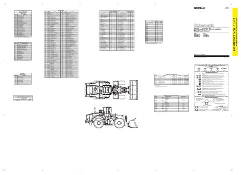
966H and 972H Wheel Loader Electrical System 966H: A6D1347-UP RYF458-UP A6G5295-UP
The connectors shown in this chart are for harness to harness connectors. Connectors that join a harness to a component are generally located at or near the component. See the Component Location Chart.
Volume 1 of 2: Chassis © 2012 Caterpillar, All Rights Reserved
Symbols
T
Pressure Symbol
13
6 33
40
Function
Actuate
Deactuate
Contact Position
47
14 29
15
10 36
5
Ground (Wired): This indicates that the component is connected to a grounded wire. The grounded wire is fastened to the machine. Ground (Case): This indicates that the component does not have a wire connected to ground. It is grounded by being fastened to the machine. Reed Switch: A switch whose contacts are controlled by a magnet. A magnet closes the contacts of a normally open reed switch; it opens the contacts of a normally closed reed switch. Sender: A component that is used with a temperature or pressure gauge. The sender measures the temperature or pressure. Its resistance changes to give an indication to the gauge of the temperature or pressure.
24
38
19
50
46
Relay (Magnetic Switch): A relay is an electrical component that is activated by electricity. It has a coil that makes an electromagnet when current flows through it. The electromagnet can open or close the switch part of the relay.
20
18 4 49
43
2
12 30
3
8 21
27 42
1
Solenoid: A solenoid is an electrical component that is activated by electricity. It has a coil that makes an electromagnet when current flows through it. The electromagnet can open or close a valve or move a piece of metal that can do work.
45
26 32
25
28
41
9
35
Magnetic Latch Solenoid: A magnetic latch solenoid is an electrical component that is activated by electricity and held latched by a permanent magnet. It has two coils (latch and unlatch) that make electromagnet when current flows through them. It also has an internal switch that places the latch coil circuit open at the time the coil latches.
23 48
Resistor, Sender and Solenoid Specifications
Related Electrical Service Manuals
Engine Control:
44
22
17
11
Form Number
165-4619 (Delco 42MT)
Circuit Breaker Symbol
Switch (Normally Closed): A switch that will open at a specified point (temp, press, etc.). No circle indicates that the wire cannot be disconnected from the component.
² Contact postion at the contacts of the harness connector.
31
16
Electric Starting Motor:
Flow Symbol
Switch (Normally Open): A switch that will close at a specified point (temp, press, etc.). The circle indicates that the component has screw terminals and a wire can be disconnected from it.
275 to 1750 kPa¹ 114-5333 A/C (High / Low) Pressure Normally Open² (39.9 to 253.8 psi) 138 ± 28 kPa 89 ± 20 kPa 117-7773 Hydraulic Filter Bypass Pressure Normally Closed (20 ± 4 psi) (12.9 ± 2.9 psi) A-B, Normally Open 8270 kPa MAX 6890 ± 345 kPa 174-4312 Park Brake Pressure A-C, Normally Closed (1200 psi MAX) (1000 ± 50 psi) A-B, Normally Open 10700 kPa MAX 8960 ± 537 kPa 175-3244 Brake Oil Pressure A-C, Normally Closed (1550 psi MAX) (1300 ± 79 psi) 1200 kPa MAX 700 ± 100 kPa A-B Normally Open 230-5771 Secondary Steering Pressure (174.0 psi MAX) (102 ± 14.5 psi) A-C Normally Closed 110.3 ± 13.8 kPa 69 kPa MIN 258-0883 Fuel Differential Pressure Normally Closed (16 ± 2 psi) (10 psi MIN) 1200 kPa MAX 700 ± 100 kPa A-B Normally Open 3E-6450 Primary Steering Pressure (174.0 psi MAX) (102 ± 14.5 psi) A-C Normally Closed ¹ With increasing pressure the closed condition can be maintained up to 2800 kpa (405 psi), with decreasing pressure the closed condition can be maintained down to 170 kpa (25psi). T
197-8820 (Denso HDB 95A)
Level Symbol
Fuse: A component in an electrical circuit that will open the circuit if too much current flows through it.
Off-Machine Switch Specification Part No.
51
177-9953 (Denso HDB 80A)
Temperature Symbol
Symbols and Definitions
39
Alternator:
Printed in U.S.A.
Harness And Wire Electrical Schematic Symbols
7
Title
972H: LCC1-UP A7D566-UP A7G2062-UP
Part No.
34 37
SENR4130
Component Description
128-7991
Solenoids:
134-2540
Resistor:
138-2924
Solenoids:
SENR3581 RENR9318
145-7028 148-2350
Sender: Solenoid:
152-8340 163-0872 168-6452 216-5338
Solenoid: Solenoid: Solenoid: Solenoids:
220-8214
Sender:
225-0300
Solenoid:
237-2234
Solenoid
239-1134
Solenoid:
Fuel Injection CAN Data Link Aux Lift Raise Prop Aux Lower Prop Dump Prop Lift Prop Lower Prop Rackback Prop T/C Temperature Variable Speed Fan Auto Reversing Fan A/C Compressor Clutch Axle Oil Cooler Clutch Transmission Clutch Fuel Level On/Off Pilot Left Anti-Drift Ride Control (3) Tilt Anti-Drift Start Aid
¹ At room temperature unless otherwise noted.
31
2
43
9
23
12
16
38 39
13
1
19
3
21
17
8
30
29
20
11
41
51
14
32
27
15
42
24
5
26
28
7
45 47
33 44
40
48 36
6
49
46
22
34 35
37
25
10
4
50
18
Resistance (Ohms)¹
Harness and Wire Symbols
1.06 ± 0.05 108 - 132
7.75 ± 1.0
Wire, Cable, or Harness Assembly Identification: Includes Harness Identification Letters and Harness Connector Serialization Codes (see sample).
Harness Identification Letter(s): (A, B, C, ..., AA, AB, AC, ...)
L-C12 3E-5179
AG-C4 111-7898 1000 5.0 ± 0.3 32.6 ± 1.6 17.6±0.6 9.4 ± 5.0 8.7 ± 0.4 Empty: 240 - 250 Full: 28 - 33 38.12 ± 1.9 33.8 20.0
L-C12 3E-5179
1
Part Number: for Connector Plug
Harness Connector Serialization Code: The "C" stands for "Connector" and the number indicates which connector in the harness (C1, C2, C3, ...).
Part Number: for Connector Receptacle
2 Plug
Receptacle Pin or Socket Number
1 2
Deutsch connector: Typical representation of a Deutsch connector. The plug contains all sockets and the receptacle contains all pins.
1 2
Sure-Seal connector: Typical representation of a Sure-Seal connector. The plug and receptacle contain both pins and sockets.
5A Fuse (5 Amps)
9X-1123
Component Part Number
325-AG135 PK-14 Harness identification code: This example indicates wire group 325, wire 135 in harness "AG".
Wire Gauge Wire Color
(Dimensions: 48 inches x 35 inches)
101
Component Location
Wire Number
Power Circuits
Fuel Injector Solenoid #1 Fuel Injector Solenoid #2 Fuel Injector Solenoid #3 Fuel Injector Solenoid #4 Fuel Injector Solenoid #5 Fuel Injector Solenoid #6 ECM 8V DC Supply Throttle Sensor Fuel Pressure Sensor Oil Pressure Sensor Engine Coolant Temperature Sensor Electrical Power Supply Intake Manifold Air Temperature Sensor Fuel Temperature Sensor Engine Speed Sensor Personality Module Engine Speed Sensor 5 Volt Sensor Supply Engine Shutdown Switch Check Programmable Parameters Atmospheric Pressure Sensor Right Turbo Inlet Pressure Sensor Filter Restrict Lamp Engine Cooling Fan Solenoid Transmission ECM Camshaft Position Sensor Implement Control Machine Security System Intake Manifold Pressure Sensor Start Aid Solenoid
FMI No.
Wire Color
36 Page,
CID 0001 0002 0003 0004 0005 0006 0041 0091 0094 0100 0110 0168 0172 0174 0190 0253 0261 0262 0267 0268 0274 0275 0283 0291 0296 0342 0596 1639 1785 2417
Wire Number
UENR2527 VOL 1 of 2
Component Identifiers (CID¹) Module Identifier (MID²) Engine Control System (MID No. 036)