RENR4398-03 May 2006 2
1
1
4
3
2
4
3
AUX
6
5
5
6
AA
TILT
A
14
13
8
9
10
11
12
A CC
DD
20
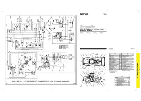
966G & 972G Series II Wheel Loader Hydraulic System
RAISE
LOWER
TILT BACK
DUMP
19 LOWER/CLOSE OPEN/RAISE
18
TO BRAKE LIGHTS
15
BB
17
7
LIFT TO TRANSMISSION CONTROL
16
7
21 B
22
24
23
A
TO TRANSMISSION CONTROL
THE RELIEF VALVE IS NOT USED ON THE FOLLOWING MACHINES:
B
AWY1-UP AXC1-UP AXE1-UP
AXJ1-UP AXN1-UP AXL1-UP
ANT1-UP ANY1-UP AXP1-UP
ANZ1-UP AWP1-UP AWZ1-UP
966G SERIES II
25
AWY431-UP AXJ636-UP ANT1-UP ANZ1-UP
972G SERIES II
26
FF
AXC526-UP AXN253-UP ANY1-UP AWP1-UP
TO BRAKE DRAIN
27
GG C
29
28
C
30
LINEAR PATTERNS Pressure Pilot Pressure Return Lines Components
IMPLEMENT PILOT/PILT STEERING RETURN
STEERING RETURN
D
STEERING LOAD SENSE SIGNAL STEERING
36, 37 32
31
33
34
49, 50, 51, KK
A
22 - 24, 27
9, 10, FF
8, 33, 37, CC, DD, MM
1, 13 - 20, 28, GG
3
48
HH
A
LL
35
B 37
36
P
C
B KK
T
X IMPLEMENT
41, LL
32, 37
JJ
38
E
31
PILOT/BRAKE
B 39
S
L1
40
38
41 43
42
29, 30
44
45
46
43
47
4
5
2
Item No.
Component
Chart A 966G II and 972G II Hydraulic Component Locations Schematic Location
Item No.
49
50
51
22 - 24, 27
32, 47
29, 30
F
38, LL
40, 42 - 48 6, 7
39, 44, 45
8, 9, 10, 48, CC, DD, FF, MM
3
AA, BB
Main Control Valve %
A1
27
Service Brake Oil Pressure Switch
C6
Auxiliary Cylinders @
A2
28
Pilot Valve (Oil Manifold)
C1
3
Tilt Cylinder
A3
29
Ball Valve (Hydraulic Lever Lock)
4
Lift Cylinders
A4
30
Pilot Control Valve
5
Front Service Brakes
A5
31
Fan Drive Motor
6
Left Pedal Assembly
32
Secondary Steering Valve *
D4
7
Right Pedal Assembly
33
Left Steering Neutralizer Valve
D4
A6
8
Service Brake Control Valve
34
Right Steering Neutralizer Valve
D5
9
Front Service Brakes Accumulator
35
Steering Cylinders
D7
10
Rear Service Brakes Accumulator
36
Hydraulic Oil Cooler Bypass Valve
11
37
Hydraulic Oil Cooler
12
Parking Brake Parking Brake Actuator
13
Orifice
A7
38
Electro-Hydraulic Control
E3
39
Implement Pump
E1 E2
14
Ride Control Diverter Valve #
A4
40
Hydraulic Oil Filter
15
Ride Control Accumulator #
A5
41
Fan Drive Pump
16
Main Relief Valve
A1
42
Screen Group
17
Line Relief Valve (Aux. Cylinder Head End) @
43
Flow Divider Valve (Brake Oil Cooler)
E2
44
Steering Pump
45
Pilot/Brake Pump
A3
46
Breaker Relief Valve
Rear Service Brakes
B5
47
Secondary Steering Pump and Electric Motor*
Accumulator Charging Valve
B6
48
Steering Metering Pump
F4
49
Steering Backup Relief Valve
F5
50
Steering Control Valve
51
Steering Crossover Relief Valve
A2
18
Line Relief Valve (Aux. Cylinder Rod End) @
19
Line Relief Valve (Tilt Cylinder Rod End)
20
Line Relief Valve (Tilt Cylinder Head End)
21 22 23
Parking Brake Control Valve
24
Parking Brake Pressure Switch
25
Check Valve
B4
26
Check Valve
C1
52 53
Brake Oil Cooler
F2
Hydraulic Oil Tank
F2
B7
F1
* Secondary Steering is an optional attachment.
% The one stem valve (third function) is an optional attachment field conversion. The two stem valve is standard. The three stem valve is an optional attachment.
31
Pressure Tap
966G II & 972G II PILOT IMPLEMENT/STEERING METERING PUMP HYDRAULIC SCHEMATIC
G
F06057
187-6676-00
1
2
3
4
5
6
21
7
49, 50, 51, KK 11, 12
36, 37
43, 53, JJ
HH
35
33, 34
GG
4 5
2
E2
A3
Chart B 966G II and 972G II Hydraulic Pressure Tap Locations
G
C3 F2
52
53
Schematic Location
2
@ Auxiliary Cylinders are an optional attachment.
1, 13 - 20, 28
Component
1
# Ride Control is an optional attachment.
SECONDARY STEERING SUCTION
52
6, 7 34, 35
MM 48
F
43, 53, JJ
39, 44, 45
21
11, 12
Chart A 966G II and 972G II Hydraulic Component Locations
Description
AA
Tilt Cylinder Rod End Pressure
BB
Tilt Cylinder Head End Pressure
CC
Rear Service Brake Pressure
DD
Front Service Brake Pressure
Schematic Location A3 A5
FF
Service Brake Accumulator Pressure
C6
GG
Implement Pilot Pump Pressure
C4
HH
Implement Pump Pressure
D1
JJ
Fluid Sampling Valve
E2
KK
Steering Pump Pressure
E5
LL
Fan Drive Pump Pressure
E3
MM
Steering Signal Pressure
F4
F3
F6
20 Page
D
RENR4398-03
HH
E
Printed in U.S.A.
© 2006 Caterpillar All Rights Reserved
Denotes Wire Code
IMPLEMENT RETURN