RENR4399-06 September 2011 Wire Description
0002
Fuel Injector Solenoid #2
0003
Fuel Injector Solenoid #3
0004
Fuel Injector Solenoid #4
0005
Fuel Injector Solenoid #5
0006
Fuel Injector Solenoid #6
0041
727
GN
SEC STR RELAY COIL+
BU
RUNNING LAMP PWR
728
BU
SEC STR INTER RELAY COIL+
104
YL
PRODUCT LINK PWR (SWITCHED)
751
GN
CLUTCH 1 REVERSE
106
WH
LIFT/TILT POSITION SENSOR PWR
752
YL
CLUTCH 2 FORWARD
Alarm - Backup
B-18
2
Sensor - Oil Pressure
F-15
8
109
OR
ALTERNATOR PWR
754
BU
CLUTCH 3 FOURTH
Alternator
I-16
3
Sensor - Tilt Position
L-10
21
110
GN
ENGINE ECM PWR (SWITCHED)
755
OR
CLUTCH 4 THIRD
112
PU
MAIN RELAY OUTPUT PWR
761
GY
LIFT POS SENSOR
RD
102
ECM 8V DC Supply
Description Control Circuits cont.
114
GN
FORWARD HORN PWR
762
YL
BUCKET/TILT POS SW
129
BU
ETHER INJECT PWR
779
WH
QUICK COUPLER (ENGAGE SOL)
136
GN
SECONDARY STEERING PWR
A701
GY
FUEL INJECTOR CYLINDER 1
0091
Throttle Sensor
138
GN
PAYLOAD MONITOR SYSTEM PWR
A702
PU
FUEL INJECTOR CYLINDER 2
0094
Fuel Pressure Sensor
150
OR
ENGINE ECM PWR (UNSWITCHED)
A703
BR
FUEL INJECTOR CYLINDER 3
0100
Oil Pressure Sensor
170
YL
PRODUCT LINK PWR (UNSWITCHED)
A704
GN
FUEL INJECTOR CYLINDER 4
0110
Engine Coolant Temperature Sensor
174
PK
UNSWITCHED BUSS PWR
A705
BU
FUEL INJECOTR CYLINDER 5
0168
Electrical Power Supply
175
PK
HOOD MOTOR PWR
A706
GY
FUEL INJECTOR CYLINDER 6
0172
Inlet Air Temperature Sensor
177
OR
MAIN CIRCUIT BREAKER PWR
A745
WH
FUEL PRESSURE
0174
Fuel Temperature Sensor
199
OR
HOOD CONTROL PWR
F713
OR
TURBO INLET PRESS SENSOR
0253
Personality Module mismatch
0254
ADEM III ECM
0261
Engine Speed Sensor
0262
5 Volt Sensor Supply
0267
Engine Shutdown Switch
0268
Check Programmable Parameters
0273
Turbo Outlet Pressure Sensor
0274
Atmospheric Pressure Sensor
306
GN
START RELAY COIL+
H746
YL
0291
Engine Cooling Fan Solenoid
308
YL
MAIN POWER RELAY COIL+
H747
BR
0296
Transmission ECM
317
YL
ETHER INJECT SOLENOID+
H795
PK
0320 0342
200 201
BK BK
MAIN CHASSIS GND OPERATOR MONITOR GND
F762 F766 G764
GY WH PK
ETHER INJECT RELAY COIL+ DETENT ENABLE INTERLOCK PARKING BRAKE SW (ON)
229
BK
ENGINE ECM GND
H713
PK
LIFT PROPORTIONAL SOL
251
BK
PAYLOAD MONITOR SYSTEM GND
H714
OR
LOWER PROPORTIONAL SOL
A274
BK
PRODUCT LINK ECM GND Basic Machine Circuits
304
WH
STARTER SOL START TERMINAL
H716
WH
IMPLEMENT ECM SOLENOID RETURN
H717
BR
PILOT SOLENOID
H718
GY
BUCKET TILT POSITION SENS (SIG)
Component
Arc Suppressor
I-14
4
Sensor - Trans. Lube Oil Temperature
F-12
7
Batteries
K-14
5
Sensor - Trans. Output Speed (Leading)
G-13
18
Breaker - ADEM Engine Control
B-14
4
Sensor - Trans. Output Speed (Trailing)
H-13
18
Breaker - Alternator
B-14
4
Sensor - Trans. Oil Temp
H-13
18
Breaker - Hood
C-14
4
Sensor - Turbo Inlet Pressure
F-13
14
Breaker - Main
B-13
4
Solenoid - A/C Clutch
I-14
3
Breaker - Running Lamp
C-14
4
Solenoid - Aux Lift Prop
I-11
19
Breaker - Unswitched Bus (Cab)
C-14
4
Solenoid - Aux Lower Prop
I-11
19
Control - ADEM III
D-9
6
Solenoids - Cylinder Head ( 1 - 6)
H-17
22
Control - Hood Raise / Lower
C-12
4
Solenoid - Dump Prop
I-10
19
Control - Product Link
A-6
7
Solenoid - Ether Injection
G-10
23
Motor - Actuator
B-15
2
Solenoid - Lift Prop
I-10
19
Motor - Fuel Priming Pump
J-15
8
Solenoid - Lower Prop
I-11
19
Motor - Secondary Steer
K-14
9
Solenoid - On / Off Pilot
I-10
19
Motor - Starter
J-12
10
Solenoids - Quick Coupler
G-7
19
Motors - Washers
G-9
11
Solenoid - Rack Back Prop
I-10
19
Relay - Back Up Alarm
K-18
12
Solenoids - Trans. Clutch
H-14
18
Relay - Ether Injection
B-12
4
Solenoid Valves - Ride Control
J-11
19 15
A-12, A-14
4
Solenoid - Variable Speed Fan
G-12
VARIABLE SPD FAN SOLENOID+
Relay - Secondary Steering
K-14
4
Switch - A/C Refrigerant
I-14
3
VARIABLE SPD FAN SOLENOID-
Relay - Secondary Steering Intermediate
L-15
9
Switch - Brake Oil Pressure
G-10
24
ENGINE ECM (SENSOR/SW RETURN)
Relay - Start
A-14
4
Switch - Disconnect
K-13
25
13
Switch - Front Axle Temperature
H-10
26
Relay - Main
321
BR
BACKUP ALARM
J700
BR
ENGINE RETARDER SOL CYL 1
Sender - Fuel Level
Camshaft Position Sensor
322
GY
FORWARD HORN
J701
GN
ENGINE RETARDER SOL 3
Sender - Torque Converter Oil Temp
C-8
8
Switch - Fuel Priming Pump
I-15
8
Sensor - Atmospheric Pressure
F-15
14
Switch - Ground Level Shutdown
A-15
27 27
Start Aid Relay Caterpillar Monitoring System Air Inlet Heater Relay
1582
Trans Lube Oil Temperature Sensor Turbo Inlet Air Pressure Sensor
Product Link ECM (MID No. 122) CID
326
PU
FUEL PRIMING PUMP
J702
BK
ENGINE RETARDER SOL COMMON
397
OR
HOOD MOTOR LOWER
R746
PK
TURBO OUTLET PRESSURE SENSOR
Sensor - Cam Shaft Speed Timing
E-15
15
Switch - Hood Actuator
B-15
ATMOSPHERIC PRESSURE SENSOR
Sensor - Coolant Temperature
F-15
8
Switch - Hydraulic Filter Bypass Pressure
G-10
24
D-16
16
Switch - Hydraulic Oil Level
G-9
17
398
0617
BU
HOOD MOTOR RAISE
GY
A300
GN
HOOD CONTROL LOWER
A893
OR
FUEL PRIMING PUMP MOTOR-
Sensor - Crank Shaft Speed Timing
A301
WH
HOOD CONTROL RAISE
G828
WH
SENSOR PRESSURE +5V
Sensor - Fuel Pressure
F-16
8
Switch - Lift Kickout Proximity
L-9
28
A307
GY
THROTTLE PEDAL POS SENS
G829
GN
SENSOR PRESSURE COMMON
Sensor - Fuel Temperature
E-15
8
Switch - Park Brake Pressure
G-10
24
G833
PK
ENGINE TEMP SENSOR COMMON
Sensor - Hydraulic Oil Temperature
G-9
17
Switch - Primary Steer
F-10
9
403
GN
ALTERNATOR (R) TERMINAL
G850
BU
AIR INLET HEATER RELAY COIL+
Sensor - Input Speed
H-13
18
Switch - Rear Axle Temp
C-7
29
416
OR
SEC STR PRESS SW (N/0)
G853
OR
ENGINE INTAKE MANIFOLD AIR TEMP #2
Sensor - Inlet Manifold Pressure
E-15
14
Switch - Secondary Steering
F-10
9
F-15
8
Switch - Tilt Kickout Proximity
L-11
30
H-11, I-10
19
Switch - Trans Filter Bypass
G-10
24
L-9
20
Monitoring Circuits
Component
R747
0168
Electrical Power Supply
417
GY
PRIMARY STR PRESS SW (N/O)
G856
WH
TDC PROBE+
Sensor - Intake Manifold Air Temp
0254
Electronic Control Module (Product Link)
419
YL
PARKING BRAKE SW (OFF)
G857
YL
TDC PROBE-
Sensor - Lift Cylinder Head End Pressure
0269
Sensor Power Supply
426
BR
XMSN FILTER BYPASS SWITCH
J843
BK
ENGINE ECM ANALOG SENSOR RTN
Sensor - Lift Position
1251
Alternator R-Terminal Signal
430
BU
AIR FILTER RESTRICTED IND
J844
GY
ENGINE ECM ANALOG SENS 5VOLTS
¹ The CID is a diagnostic code that indicates which component is faulty.
432
PK
BRAKE OIL PRES SWITCH (ON)
900
PU
CLUTCH 5 SECOND
442
GY
HYD TANK OIL TEMP SENSOR
901
WH
CLUTCH 6 FIRST
² The MID is a diagnostic code that indicates which electronic control module diagnosed the fault.
Failure Mode Identifiers (FMI)¹ FMI No.
Failure Description
0
Data valid but above normal operational range.
1
Data valid but below normal operational range.
2
Data erratic, intermittent, or incorrect.
3
Voltage above normal or shorted high.
4
Voltage below normal or shorted low.
5
Current below normal or open circuit.
6
Current above normal or grounded circuit.
443
YL
TC OUTLET TEMP SENSOR
944
OR
CAT DATA LINK+
447
PK
FUEL LEVEL SENSOR
945
BR
CAT DATA LINKIMPLEMENT ECM SENSOR RTRN
450
YL
ENGINE ECM (ENGINE SPD)
953
GY
453
PK
SEC STR PRESS SW (N/O)
962
OR
TRANSMISSION ECM SENSOR RTRN
484
YL
PRIMARY STR PRESS SW (N/C)
975
WH
XMSN ECM SOLENOID/INDICATOR RTN
496
WH
HYD TANK OIL LEVEL SENS
976
OR
RIDE CONTROL ON SOLENOID
E416
PU
LIFT CYL HEAD END PRESS SENSOR
994
GY
OIL PRESSURE (FILTERED)
E455
BR
HYDRAULIC FILTER BYPASS SW
995
BU
Coolant Temperature
F421
YL
FUEL TEMPERATURE
A982
BR
ENGINE ECM THROTTLE/IND 8VOLTS
G479
WH
SERVICE ENGINE INDICATOR
E900
WH
XMSN OUTPUT SPD SENS LEADING+
G485
BU
FRONT AXLE OIL TEMP SW
E901
GN
XMSN OUTPUT SPD SENS LEADING-
G486
GN
REAR AXLE OIL TEMP SW
E906
OR
XMSN OUTPUT SPD SENS TRAILING+
Accessory Circuits
E907
GY
XMSN OUTPUT SPD SENS TRAILING-
506
PU
FRONT WASHER PUMP+
E908
BR
XMSN INPUT SPD SENSOR+
507
WH
REAR WASHER PUMP+
E909
WH
XMSN INPUT SPD SENSOR-
513
OR
A/C CLUTCH SOLENOID+
E919
YL
AUX LIFT PROPORTIONAL SOL
521
YL
A/C SELECT SW (A/C POSTION)
E920
BR
AUX LOWER PROPORTIONAL SOL
522
WH
A/C CLUTCH SOLENOID-
E921
PK
RACKBACK PROPORTIONAL SOL
C529
GY
LIFT CYL HE PRESS SENS
E922
GN
DUMP PROPORTIONAL SOL
C530
BU
LIFT POSITION SENSOR
E963
BK
CRANK RPM SENSOR-
Lighting Circuits
E964
WH
CRANK RPM SENSOR+
603
PK
ROTARY BEACON
E965
BU
CAM RPM SENSOR-
604
OR
STOP LAMP
E966
YL
CAM RPM SENSOR+
605
YL
LH TURN LAMPS
K933
GN
OPERATOR MONITOR SENSOR PWR
606
GY
RH TURN LAMPS
K977
PK
XMSN OIL TEMP SENSOR
608
GN
REAR FLOOD LAMPS
L983
WH
FUEL INJECTOR RTN CYL 1-2
611
PU
HEAD LAMP (HIGH)
L984
OR
FUEL INJECTOR RTN CYL 3-4
612
GY
BACKUP LAMP
L985
YL
FUEL INJECTOR RTN CYL 5-6
614
PU
LICENSE PLATE/RH TAIL/DASH LAMPS
N939
GN
RIDE CONTROL AUTO SOLENOID
615
YL
FORWARD CAB FLOOD LAMPS
P976
BR
QUICK COUPLER RELEASE SOLENOID
Mechanical system not responding properly.
617
BR
LH TAIL/CLEARANCE LAMPS
R971
YL
XMSN LUBE OIL TEMP SENSOR
8
Abnormal frequency, pulse width, or period.
619
GN
FWD FLOOD/LO BEAM LAMPS
R974
OR
ETHER INJECT SWITCH
9 10
Abnormal update. Abnormal rate of change.
X918
PU
GND LEVEL SHUTDOWN SW (N/O)
709
OR
XMSN ECM SENS/IND (+8VOLTS)
X919
WH
GND LEVEL SHUTDOWN SW (N/C)
11
Failure mode not identifiable.
12
Bad device or component.
13
Out of calibration.
14
Parameter failures.
15
Parameter failures.
16
Parameter not available.
17
Module not responding.
18
Sensor supply fault.
19
Condition not met.
20
Schematic Machine Location Location
Component
Crankshaft Position Sensor
0562
7
Machine Location
C-16
0545
1589
Ground Circuits
Component Location Schematic Location
Control Circuits
Parameter failures.
¹The FMI is a diagnostic code that indicates what type of failure has occurred.
Event Code
High Engine Coolant Temperature Derate
E017
High Engine Coolant Temperature Warning
E025
High Inlet Air Temperature Derate
E027
High Inlet Air Temperature Warning
E039
Low Engine Oil Pressure Derate
E095
Fuel Filter Restriction Warning
E096
High Fuel Pressure
E100
Low Engine Oil Pressure Warning
E190
Engine Overspeed Warning
9 14
3
13 2
15 16
8
29
1
19
34
7 32
6
35
45
18
22 4
28
23
10
12
26
33
31
30
21
20
27 11 17
966G and 972G Series II Wheel Loaders Electrical System 14
23
3
7 32
22 4 16 8 1 25 15
12 2
36
35 18 17
11
9
29
28 34 45 20
966G: AXJ1-1374 AXL1-276 ANZ1-540
30
972G: AXN1-336 AWP1-276 AXP1-167
24
10
6
27
33
31
13
5
19
21
26
Machine locations are repeated for components located close together.
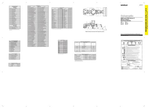
Machine Harness Connector And Component Location Volume 1 of 2: Chassis Wiring (Pilot Hydraulics and HMU Steering) © 2011 Caterpillar, All Rights Reserved
Connector Number CONN 1 CONN 2 CONN 3 CONN 4 Timing / Calibration Probe CONN 5 CONN 6 CONN 7 Aux. Start Receptacle CONN 8 CONN 9 CONN 10 CONN 11 CONN 12 CONN 13 CONN 14 CONN 15 CONN 16 CONN 17 CONN 18 CONN 19 CONN 20 CONN 21 CONN 22 CONN 23 CONN 24 CONN 25 CONN 26 CONN 27 CONN 28 CONN 29 CONN 30 CONN 31 CONN 32
Schematic Location
Machine Location
I-17 G-15 F-15 E-15 D-15 I-14 J-14 L-13 A-12 C-10 H-10, I-8 J-9 J-9 H-3, J-3, J-9, L-3 H-3, J-9 H-3, K-9 K-9, I-3 K-9, I-3 L-8, L-10 I-5, K-7, L-5 G-7 C-7 B-5 H-9 K-1 J-2 I-3
12 22 8 8 16 8 1 9 4 6 19 19 20
G-2 G-2 F-2 E-2 D-2
Harness And Wire Electrical Schematic Symbols Part No.
Component Description
Resistance (Ohms)¹
Dump Prop T
Lower Prop 138-2924
Solenoid:
Aux Lower Prop
Pressure Symbol
7.75 ± 1.0
Rackback Prop
147-5399
Solenoids: Transmission Clutch
148-2350
Solenoid: Variable Speed Fan
5.0 ± 0.3
152-6761
Solenoid: On / Off Pilot
32.6 ± 1.6
152-8340
Solenoids: Ride Control
32.6 ± 1.6
163-0872
Solenoid: A/C Clutch
175-3088
Alternator:
185-5294 165-4619
Consist:
(Delco 42MT type 400)
Switch (Normally Open): A switch that will close at a specified point (temp, press, etc.). The circle indicates that the component has screw terminals and a wire can be disconnected from it.
17.6 ± 0.6
Switch (Normally Closed): A switch that will open at a specified point (temp, press, etc.). No circle indicates that the wire cannot be disconnected from the component.
560 to 716 @ 54ºC (130ºF)
Ground (Wired): This indicates that the component is connected to a grounded wire. The grounded wire is fastened to the machine.
Full: 28 - 33
Sender: Fuel Level
Empty: 240 - 250 3E-6332
Solenoid: Start Aid
3E-8575
Solenoid: Quick Coupler
6
Ground (Case): This indicates that the component does not have a wire connected to ground. It is grounded by being fastened to the machine.
24.9 ± 0.4
¹ At room temperature unless otherwise noted.
Reed Switch: A switch whose contacts are controlled by a magnet. A magnet closes the contacts of a normally open reed switch; it opens the contacts of a normally closed reed switch.
Off Machine Switch Specification Function
Actuate
Sender: A component that is used with a temperature or pressure gauge. The sender measures the temperature or pressure. Its resistance changes to give an indication to the gauge of the temperature or pressure.
T
Deactuate
Contact Position Relay (Magnetic Switch): A relay is an electrical component that is activated by electricity. It has a coil that makes an electromagnet when current flows through it. The electromagnet can open or close the switch part of the relay.
275 to 1750 kPa¹ Normally Open² (39.9 to 253.8 psi) Rear Axle Temperature 125 ± 3.0°C 117°C Min 155-8999 Normally Closed (242.6°F Min) (257 ± 37.4°F) Front Axle Temperature A-B, Normally Open 6890 ± 345 kPa 8270 kPa MAX 174-4312 Park Brake Pressure (1200 psi MAX) A-C, Normally Closed (1000 ± 50 Psi) 10700 kPa MAX 8960 ± 537 kPa A-B, Normally Open 175-3244 Brake Oil Pressure (1500 psi MAX) (1300 ± 79 Psi) A-C, Normally Closed Primary Steering Pressure 1200 kPa MAX 700 ± 100 kPa A-B Normally Open 3E-6450 (174.0 psi MAX) (102 ± 14.5 Psi) Secondary Steering Pressure A-C, Normally Closed 110.3 - 137.9 kPa³ 86.2 - 103.4 kPa³ 7X-8549 Hydraulic Filter Bypass Pressure Normally Open (16 - 20 psi) (12.5 - 15) ¹ A hysteresis band exists: with increasing pressure the closed condition can be maintained up to 2800 kpa (405 psi), with decreasing pressure the closed condition can be maintained down to 170 kpa (25psi). ² Contact position at the contacts of the harness connector. A/C (High / Low) Pressure
Solenoid: A solenoid is an electrical component that is activated by electricity. It has a coil that makes an electromagnet when current flows through it. The electromagnet can open or close a valve or move a piece of metal that can do work. Magnetic Latch Solenoid: A magnetic latch solenoid is an electrical component that is activated by electricity and held latched by a permanent magnet. It has two coils (latch and unlatch) that make electromagnet when current flows through them. It also has an internal switch that places the latch coil circuit open at the time the coil latches.
Harness and Wire Symbols Wire, Cable, or Harness Assembly Identification: Includes Harness Identification Letters and Harness Connector Serialization Codes (see sample).
SEBU7351
L-C12 3E-5179
L-C12 3E-5179
1
Part Number: for Connector Plug
Harness Connector Serialization Code: The "C" stands for "Connector" and the number indicates which connector in the harness (C1, C2, C3, ...).
Part Number: for Connector Receptacle
2
SENR3581
Product Link System
Harness Identification Letter(s): (A, B, C, ..., AA, AB, AC, ...)
AG-C4 111-7898
Form Number
RENR1285
Circuit Breaker Symbol
Fuse: A component in an electrical circuit that will open the circuit if too much current flows through it.
8.15 ± 0.6
Sender: Torque Converter Oil Temperature
220-8214
114-5333
ADEM III ECM
Flow Symbol
72 to 82 @ 110ºC (230ºF)
Part No.
SENR4130
Level Symbol
Symbols and Definitions
Aux Lift Prop
Related Electrical Service Manuals
Electric Starting Motor:
Temperature Symbol
Lift Prop
20 20 34 34 34 34 33 31 36 32 35 34 34 45 32 32 32 32 32
Symbols
Resistor, Sender and Solenoid Specifications
³ Specifications represent a differential pressure measurement.
Title
Printed in U.S.A.
Connector Location
Condition
E015
36
25
The connectors shown in this chart are for harness to harness connectors. Connectors that join a harness to a component are generally located at or near the component. See the Component Location Chart.
Event Codes For ADEM III ECM
24
5
Plug
Receptacle Pin or Socket Number
1 2
Deutsch connector: Typical representation of a Deutsch connector. The plug contains all sockets and the receptacle contains all pins.
1 2
Sure-Seal connector: Typical representation of a Sure-Seal connector. The plug and receptacle contain both pins and sockets.
5A Fuse (5 Amps)
9X-1123
Component Part Number
325-AG135 PK-14 Harness identification code: This example indicates wire group 325, wire 135 in harness "AG".
Wire Gauge Wire Color
(Dimensions: 48 inches x 35 inches)
Fuel Injector Solenoid #1
BATTERY+
101
Description Power Circuits
Component
0001
Wire Color
Wire Color
36 Page,
CID
Wire Number
Wire Number
RENR4399-06 VOL 1 of 2
Component Identifiers (CID¹) Module Identifier (MID²) ADEM III ECM (MID No. 036)