Component AIH Alarm - Backup Alternator Arc Suppressor - A/C Arc Suppressor - Quick Coupler Arc Suppressor - Secondary Steering Arc Suppressor - Start Relay Batteries Block Asm. Breaker - AIH
Machine Location 1 2 3 3 4 5 6 7 7 6
I-12 I-12 H-12 I-12 H-12 H-12 F-12 I-10 B-4 J-12 C-4 A-10 H-13 C-4 H-8 I-9 F-10 G-13
6 6 6 6 6 6 8 6 9 10 11 1 12 11 5 13 1 63
H-12 I-8 H-12 D-8 I-13 E-8 D-13 D-13 D-13 I-2 C-13 H-5 D-13 J-3 F-2
6 5 6 8 14 15 16 16 17 18 1 19 16 20 20
Breaker - Belly Guard Actuator Breaker - Hood Actuator Breaker - Main Breaker - Running Lamp Breaker - Start Breaker - Unswitched Bus (Cab) Control - Engine Control - Hood Raise/Lower Motor - Autolube Pump Motor - Belly Guard Motor - Front Washer Motor - Fuel Priming Pump Motor - Hood Actuator Motor - Rear Washer Motor - Secondary Steering Motor - Starter Relay - AIH Relay - Backup Relay - Main Relay - Secondary Steering Intermediate Relay - Start Resistor - CAN Sender - Fuel Level Sender - T/C Temperature Sensor - Atmospheric Pressure Sensor - Boost Pressure Sensor - Coolant Temperature Sensor - Front Axle Oil Temperature Sensor - Fuel Pressure Sensor - Hydraulic Oil Temperature Sensor - Intake Manifold Air Temp Sensor - Lift Cylinder Head End Pressure Sensor - Lift Position
Schematic Location D-13 D-13 A-9 J-2 J-2 C-13 G-8 G-8 H-8 H-8 F-10 A-11
Machine Location 17 1 21 22 23 17 24 24 25 26 27 3
Solenoid - Aux Third Function (Forward) Solenoid - Aux Third Function (Rearward) Solenoid - Axle Cooler Clutch Solenoid - Dump Anti-Drift Solenoid - Dump Prop Solenoid - Lower Anti-Drift Solenoid - Lower Prop Solenoid - Pilot Hydraulic Supply Solenoid - Quick Coupler Solenoid - Rack Back Prop Solenoid - Raise Prop Solenoid - Ether Aid Solenoid - Variable Speed Fan Solenoids - Cylinder Head ( 1 - 6) Solenoids - Ride Control (1-3) Solenoids - Trans. Clutch Switch - A/C Refrigerant
D-2, G-1 G-2, G-1 F-10 D-2, H-3 D-2, G-1 G-3, C-2 C-2, G-1 C-2, G-1 E-1 D-2, H-1 C-2, G-1 D-7 H-9 E-14 D-2, G-3 G-8 B-11
20 20 1 20 20 20 20 20 4 20 20 29 28 30 20 25 3
Switch - Belly Guard Actuator Switch - Brake Oil Pressure Switch - Bucket Position Switch - Disconnect Switch - Fork Position Switch - Fuel Pressure Switch - Fuel Priming Pump Switch - Ground Level Shutdown Switch - Hood Actuator Switch - Hydraulic Filter Bypass Pressure Switch - Park Brake Pressure Switch - Primary Steering Pressure Switch - Secondary Steering Pressure Switch - Trans Filter Bypass
J-11 H-9 F-1 J-10 F-1 C-13 A-11 G-13 G-13 C-4 C-4 I-7 H-7 C-4
6 3 32 6 32 1 1 6 6 33 34 5 5 33
Component Sensor - Oil Pressure Sensor - Rail Pressure Sensor - Rear Axle Oil Temp. Sensor - Rotary Lift Position Sensor - Rotary Tilt Position Sensor - Speed Timing Group Sensor - Trans. Output Speed (Leading) Sensor - Trans. Output Speed (Trailing) Sensor - Transmission Input Speed Sensor - Transmission Oil Temperature Sensor - Turbo Inlet Pressure Solenoid - A/C Clutch
7
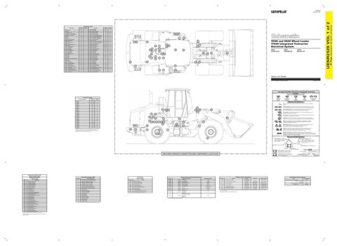
950H and 962H Wheel Loader IT62H Integrated Toolcarrier Electrical System
41
14
35
12
6
5 29 13
4
39
10
43
38
21
37
24
3 27
950H: N1A4215-UP
40
36 20 25
19
30 17
32
IT62H: M5G479-UP
23
8 1
26
15
16
28
63
18
962H: N4A2060-UP
22
42 34
2
11
33
9
Volume 1 of 2: Chassis © 2011 Caterpillar, All Rights Reserved
Printed in U.S.A.
Harness And Wire Electrical Schematic Symbols Symbols Connector Location
T
Schematic Location
Machine Location
CONN 1
C-14
2
CONN 2
C-14, D-14
2
CONN 3
I-14, J-14
35
CONN 4
I-14, J-14
35
CONN 5
C-12
16
CONN 6
C-13
16
CONN 7
E-13
1
CONN 8
J-10
6
CONN 9
A-9
36
CONN 10
D-8
37
CONN 11
E-8
13
CONN 12
F-8
13
Connector Number
CONN 13
I-7
5
CONN 14
B-6
38
CONN 15
C-6
34
CONN 16
G-5
39
CONN 17
G-5
39
CONN 18
F-5
39
CONN 19
E-5
39
CONN 20
H-4
40
CONN 21
I-2, I-3, F-2
41
CONN 22
H-3, H-2, E-2
22
CONN 23
J-3
42
CONN 24
E-2
20
CONN 25
I-3, E-2
20
CONN 26
F-2
43
The connectors shown in this chart are for harness to harness connectors. Connectors that join a harness to a component are generally located at or near the component. See the Component Location Chart.
Pressure Symbol
Temperature Symbol
Level Symbol
Circuit Breaker Symbol
Flow Symbol
Symbols and Definitions Fuse: A component in an electrical circuit that will open the circuit if too much current flows through it. Switch (Normally Open): A switch that will close at a specified point (temp, press, etc.). The circle indicates that the component has screw terminals and a wire can be disconnected from it.
41 9
38
39
Switch (Normally Closed): A switch that will open at a specified point (temp, press, etc.). No circle indicates that the wire cannot be disconnected from the component.
32
22
42 43
27
Ground (Wired): This indicates that the component is connected to a grounded wire. The grounded wire is fastened to the machine.
29 Ground (Case): This indicates that the component does not have a wire connected to ground. It is grounded by being fastened to the machine.
37
30 1
16
19
23
7
17 13
8
3
11
15
25
63
2
24
14
36
21
Sender: A component that is used with a temperature or pressure gauge. The sender measures the temperature or pressure. Its resistance changes to give an indication to the gauge of the temperature or pressure.
T
34
28
12
20
6
26 35
Reed Switch: A switch whose contacts are controlled by a magnet. A magnet closes the contacts of a normally open reed switch; it opens the contacts of a normally closed reed switch.
33
40
Relay (Magnetic Switch): A relay is an electrical component that is activated by electricity. It has a coil that makes an electromagnet when current flows through it. The electromagnet can open or close the switch part of the relay.
4
Solenoid: A solenoid is an electrical component that is activated by electricity. It has a coil that makes an electromagnet when current flows through it. The electromagnet can open or close a valve or move a piece of metal that can do work.
5
Magnetic Latch Solenoid: A magnetic latch solenoid is an electrical component that is activated by electricity and held latched by a permanent magnet. It has two coils (latch and unlatch) that make electromagnet when current flows through them. It also has an internal switch that places the latch coil circuit open at the time the coil latches.
10
Harness and Wire Symbols 18
Wire, Cable, or Harness Assembly Identification: Includes Harness Identification Letters and Harness Connector Serialization Codes (see sample).
Harness Identification Letter(s): (A, B, C, ..., AA, AB, AC, ...)
L-C12 3E-5179
AG-C4 111-7898
L-C12 3E-5179
Harness Connector Serialization Code: The "C" stands for "Connector" and the number indicates which connector in the harness (C1, C2, C3, ...).
1
Part Number: for Connector Plug
Part Number: for Connector Receptacle
2 Plug
CID 0001 0002 0003 0004 0005 0006 0041 0042 0091 0094 0100 0110 0164 0168 0172 0190 0253 0261 0262 0267 0268 0269 0274 0275 0283 0291 0296 0342 0596 1639 1785
Component Fuel Injector Solenoid #1 Fuel Injector Solenoid #2 Fuel Injector Solenoid #3 Fuel Injector Solenoid #4 Fuel Injector Solenoid #5 Fuel Injector Solenoid #6 ECM 8V DC Supply Injector Actuation Valve Throttle Sensor Fuel Pressure Sensor Oil Pressure Sensor Engine Coolant Temperature Sensor Injector Actuation Pressure Sensor Electrical Power Supply Intake Manifold Air Temperature Sensor Engine Speed Sensor Personality Module Engine Speed Sensor 5 Volt Sensor Supply Engine Shutdown Switch Check Programmable Parameters Sensor Power Supply Atmospheric Pressure Sensor Right Turbo Inlet Pressure Sensor Filter Restrict Lamp Engine Cooling Fan Solenoid Transmission ECM Camshaft Position Sensor Implement Control Machine Security System Intake Manifold Pressure Sensor
¹ The CID is a diagnostic code that indicates which circuit is faulty. ² The MID is a diagnostic code that indicates which electronic control module diagnosed the fault.
Event Codes Engine Control
Failure Mode Identifiers (FMI)¹ FMI No.
Failure Description
0
Data valid but above normal operational range.
1
Data valid but below normal operational range.
2
Data erratic, intermittent, or incorrect.
3
Voltage above normal or shorted high.
4
Voltage below normal or shorted low.
5 6
Event Code
Condition
Resistor, Sender and Solenoid Specifications Part No.
Component Description
134-2540
Resistor:
CAN Data Link
120
145-7028
Sender:
T/C Temperature
1250
148-2350
Solenoid:
Variable Speed Fan
5.0 ± 0.3
163-0872
Solenoid:
A/C Compressor Clutch
17.6±0.6
183-7595
Solenoid:
Axle Cooler Clutch
5.0 ± 0.3
E096
High Fuel Pressure
E172
High Air Filter Restriction
E194
High Exhaust Temperature
Current below normal or open circuit.
E198
Low Fuel Pressure
225-0300
Solenoid:
Pilot Hydraulic Supply
Current above normal or grounded circuit.
E360
Low Engine Oil Pressure
241-5895
Solenoid:
Auto/Reverse Fan
7
Mechanical system not responding properly.
E361
High Engine Coolant Temperature
245-4659
Sender:
8
Abnormal frequency, pulse width, or period.
E362
Engine Overspeed
244-3114
Solenoid:
E390
Fuel Filter Restriction
239-1134
Solenoid:
E441
Idle Elevated to Increase Battery Voltage
E539
High Intake Manifold Air Temperature
9
Abnormal update.
10
Abnormal rate of change.
11
Failure mode not identifiable.
12
Bad device or component.
13
Out of calibration.
14
Parameter failures.
15
Parameter failures.
16
Parameter not available.
17
Module not responding.
18
Sensor supply fault.
19
Condition not met.
20
Parameter failures.
¹The FMI is a diagnostic code that indicates what type of failure has occurred.
Off Machine Switch Specification Resistance (Ohms)¹
Fuel Level Transmission Clutch
Start Aid Dump Anti-Drift 262-5265 Solenoid: Lower Anti-Drift Ride Control 3 Aux 3rd Function Forward Aux 3rd Function Rearward Dump Prop 285-5730 Solenoid: Racback Prop Raise Prop ¹ At room temperature unless otherwise noted.
38.12 ± 1.9 35 ± 0.5 Empty: 240 - 250 Full: 28 - 33 8.7 ± 0.4 20.0 33.8
5.0 ± 0.3
1 2
Deutsch connector: Typical representation of a Deutsch connector. The plug contains all sockets and the receptacle contains all pins.
1 2
Sure-Seal connector: Typical representation of a Sure-Seal connector. The plug and receptacle contain both pins and sockets.
5A 9X-1123
Fuse (5 Amps)
Component Part Number
325-AG135 PK-14
MACHINE HARNESS CONNECTOR AND COMPONENT LOCATIONS
Component Identifiers (CID¹) Module Identifier (MID²) Engine Control System (MID No. 036)
Receptacle Pin or Socket Number
Part No.
Function
Actuate
Related Electrical Service Manuals Deactuate
Contact Position
275 to 1750 kPa¹ Normally Open² (39.9 to 253.8 psi) 138 ± 28 kPa 89 ± 20 kPa Normally Closed 117-7773 Hydraulic Filter Bypass Pressure (20 ± 4 psi) (12.9 ± 2.9 psi) A-B, Normally Open 8270 kPa MAX 6890 ± 345 kPa 174-4312 Park Brake Pressure A-C, Normally Closed (1200 psi MAX) (1000 ± 50 psi) A-B, Normally Open 10700 kPa MAX 8960 ± 537 kPa 175-3244 Brake Oil Pressure A-C, Normally Closed (1550 psi MAX) (1300 ± 79 psi) Primary Steering Presure 1200 kPa MAX 700 ± 100 kPa A-B Normally Open 230-5771 Secondary Steering Pressure (174.0 psi MAX) (102 ± 14.5 psi) A-C Normally Closed 110.3 ± 13.8 kPa 69 kPa MIN 258-0883 Fuel Differential Pressure Normally Closed (16 ± 2 psi) (10 psi MIN) ¹ With increasing pressure the closed condition can be maintained up to 2800 kpa (405 psi), with decreasing pressure the closed condition can be maintained down to 170 kpa (25psi). ² Contact postion at the contacts of the harness connector. 114-5333
A/C (High / Low) Pressure
Harness identification code: This example indicates wire group 325, wire 135 in harness "AG".
Title
Form Number
Cross Reference for Electrical Connectors:
REHS0970
Alternator: 177-9953
SENR4130
197-8820 Electric Starting Motor: 207-1517 Engine Control:
SENR3581 RENR9319
Wire Gauge Wire Color
(Dimensions: 48 inches x 35 inches)
Component Location Schematic Location F-9 G-13 H-9 B-11 F-1 I-8 H-12 J-10 J-10 H-12
36 Page,
UENR2529 VOL 1 of 2
UENR2529 December 2011