+8 Volts Sensor Supply
0070
Parking Brake Switch
0149
Ride Control Solenoid #2
0168
Electrical Systems Voltage
0177
Transmission Oil Temperature Sensor
0190
Engine Speed Sensor
0270
Cat Monitor Systems Harness Code
0363
Ride Control Solenoid
0367
Ride Control Switch
0368
Transmission AUTO/MAN Switch
0444
Start Relay
0562
Unable to Communicate With Cat Monitor System
0582
Transmission Output Speed Sensor 1
0617
Air Heater Relay
0621
Downshift Switch
0622
Up Shift Switch
0623
Direction Switch
0631
Transmission Clutch Solenoid #1
0632
Transmission Clutch Solenoid #2
0633
Transmission Clutch Solenoid #3
0634
Transmission Clutch Solenoid #4
0635
Transmission Clutch Solenoid #5
0636
Transmission Clutch Solenoid #6
0668
Transmission Shift Lever
0672
Torque Convert Output Speed Sensor
0673
Torque Output Speed Sensor
0674
Transmission Intermediate Speed Sensor 1
0675
Transmission Intermediate Speed Sensor 2
0688
Variable Horsepower Solenoid
0793
Primary Steering Pressure Switch
0794
Secondary Steering Pressure Switch
0795
Secondary Steering Intermediate Relay
¹ The CID is a diagnostic code that indicates which component is faulty. ² The MID is a diagnostic code that indicates which electronic control module diagnosed the fault.
FMI No.
Failure Mode Identifiers (FMI)¹ Failure Description
0
Data valid but above normal operational range.
1
Data valid but below normal operational range.
2
Data erratic, intermittent, or incorrect.
3
Voltage above normal or shorted high.
4
Voltage below normal or shorted low.
5
Current below normal or open circuit.
6
Current above normal or grounded circuit.
7
Mechanical system not responding properly.
8
Abnormal frequency, pulse width, or period.
9
Abnormal update.
10
Abnormal rate of change.
11
Failure mode not identifiable.
12
Bad device or component.
13
Out of calibration.
14
Parameter failures.
15
Parameter failures.
16
Parameter not available.
17
Module not responding.
18
Sensor supply fault.
19
Condition not met.
20
Parameter failures.
¹The FMI is a diagnostic code that indicates what type of failure has occurred.
Component identifiers (CID¹) and Module Identifier (MID²) for Caterpillar Monitoring System (MID No. 030) CID
Component
0084
Ground Speed Sensor
0096
Fuel LEvel Sensor
0100
Engine Oil Pressure Sensor
0110
Engine Coolant Temperature Sensor
0177
Torque Converter Oil Temperature Sensor
0248
Data Link
0263
+8 Volts Sensor Supply
0271
Action Alarm
0324
Action Lamp
0523
Engine Speed Sensor
0600
Hydraulic Oil Temperature Sensor
0601
Brake Air Pressure Sensor
0819
Display Data Link
0821
9 Volt Display Power Supply
0830
Brake Oil Temperature Sensor
Wire Color
101 102 105 108 109 112 113 114 118 120 122 123 124 126 127 128 129 130 133 134 135 136 138 144 146 158 167 175 177 188
RD RD RD BU RD PU OR GN GY YL BU WH GN PK OR PK BU GN OR YL BU GN GN GN GY BR OR PK OR WH
200 201 202 250 251 270 271 272 273 274 275 290 291 299 A219 A273
BK BK BK BK BK BK BK BK BK BK BK BK BK BK BK BK
301 304 306 307 308 310 311 321 322 326 334 373 397 398 A300 A301
BU WH GN OR YL PU WH BR GY PU BU GN OR BU GN WH
403 405 410 411 416 417 419 432 441 442 443 447 450 453 484 496 499 C413 C414 E416 G485 G486
GN GY WH PK OR GY YL PK OR GY YL PK YL PK YL WH GY YL BU PU BU GN
500 501 502 503 504 505 506 507 508 509 511 512 513 515 516 517 518 521 522 537 538 539 540 A513 A523
BR GN OR BR YL BU PU WH PU WH BR GN OR GY GN BU OR YL WH GN BR BU WH PK PU
Description Power Distribution Circuits Bat (+) (Not Application Specific) Hd Lmp Key Start Sw Aux Ckt Alt Output (+) Term. Main Power Rly Output Opr Mon Panel VMIS B+ Switched Warning Horn (Forward) Aux Ckt Aux Ckt Aux Ckt Aux Ckt A/C Xmsn Ctrl Aux Ckt Aux Ckt Aux Ckt Aux Ckt Aux Ckt Aux Ckt Aux Ckt Sec Ster Auto Lube Pump To Payload Mon Aux Ckt Aux Ckt Aux Ckt Aux Ckt Aux Ckt Main Brkr Aux Ckt Ground Circuits Main Chassis Operator Monitor Return XMSN Ctrl Payload Mon - Customer Gnd Payload Mon - System Gnd CMS Ident Code 0 CMS Ident Code 1 CMS Ident Code 2 CMS Ident Code 3 CMS Ident Code 4 CMS Ident Code 5 CMS Service CMS Clear WTL Impl Ctrl Gnd ETAC Ctrl Gnd MAC-14 Trans Ctrl BBasic Machine Circuits Starter No. 1 Sol Starter Relay No. 1 Output Starter Relay Coil Key Start SW Main Power Relay Coil Start Aid SW To Start Aid Sol Start Aid Sol To Temp SW Backup Alarm Lamp Travel Alarm Warning Horn (Forward) Key Start SW "C" Term. Start Aid Sol #2 Start Aid Switch To Timer Hood Raise Motor Hood Raise Motor Hood Raise Relay Coil Hood Raise Relay Coil Monitoring Circuits Alternator (R) Term. Opr Mon Oil Press. (Low Setting) Opr Mon Action Alarm Opr Mon Master Sec Ster SW Primary Ster SW Opr Mon Parking Brake Opr Mon Brake Press. (Oil) Eng Coolant Temp Gauge Hyd System Temp Gauge Power Train Temp Gauge Fuel Level Gauge Tach Sender (+) Sec Ster Action Lamp Primary Ster Lamp Opr Mon Panel Hyd Oil Level Opr Mon Implement Oil Filter VMIS Display Data VMIS Display Load PMS Lift Cyl Press Sensor (Was B413) Opr Mon Front Brake Temperature Opr Mon Rear Brake Temperature Accessory Circuits Wiper - Front (Park) Wiper - Front (Low) Wiper - Front (HI) Wiper - Rear (Park) Wiper - Rear (Low) Wiper - Rear (HI) Washer - Front Washer - Rear Radio Speaker - Left Radio Speaker - Left (Common) Radio Speaker - Right Radio Speaker - Right (Common) A/C Compressor/Refrigerant Pressure SW Blower Motor (HI) Blower Motor (Medium) Blower Motor (Low) Hazard Flasher To SW A/C SW To Refrigerant SW A/C Clutch To Thermostat SW Turn Signal SW To Flasher Hazard Indicator Turn Signal Indicator Basic/Right Turn Signal Indicator Left DC/DC Converter Memory Output Temp Potentiometer Pos 1
Component Location
Wire Number
Wire Color
A524 A525 A526 A527 A541 A592 A593 A594 A595 A596 C529 C530
BR GN PK BU PU BU OR WH GN YL GY BU
603 604 605 605 606 608 610 611 612 614 615 617 619 633 646 647 661 662 663 691 692
PK OR YL YL GY GN OR PU GY PU YL BR GN BU OR GN GN YL GY GY YL
709 720 727 728 751 752 754 755 761 762 795 E701 E702 E707 E708 E735 F781 F784 F793 G728 G750 G755 G760 G761 G762 G763 G764 G766 G767 G768 G785 H713 H714 H716 H717 818 819 900 901 910 944 945 961 964 973 975 976 977 E900 E901 E902 E903 E904 E905 E906 E907 E908 E909 E919 E920 E922 E923 E924 E925 E926 E927 E928 E930 E932 E933 E936 E955 G939 G954 K933 K977 N939 P910
OR PU GN BU GN YL BU OR GY YL YL PK OR GN PK PU BR YL OR YL BU GY WH YL BR PU PK GN WH GN OR PK OR WH BR BR GY PU WH YL OR BR BR BU BR WH OR YL WH GN PU YL BR BU OR GY BR WH YL BR GN PK YL OR BU GN WH BU PK YL WH OR PK GN GN PK GN BR
Component
Schematic Location
Part No.
Machine Location
Actuator - Blend Door Actuator - Hood As. Actuator - Water Valve Alarm - Action Alarm - Backup Alternator Batteries Breaker - Alt Breaker - Hood Breaker - Main Breaker - Running Lamp Breakers - 15A Control - Cat Monitoring System Control - Power Train ECM Control - Transmission Shift Lever Control - Water Valve/Blend Door Control - WLPCS ECM Converter - Voltage Dimmer - Control Fuses Fuses - 10A Fuses - 15A Gauge - Quad Ground - Cab Ground - Cab Ground - Cab Ground - Cab Ground - Cab Ground - Left Frame Boss Ground - Right Rear Frame Ground - Steer Column Ground - Strap Frame to Cab Ground - To Engine Ground - To Engine Block Ground - To Engine Cyl Head Heater - Air Inlet Horn Horn Horn Horns - Forward Horns - Forward Keypad - WLPCS Motor - Actuator Motor - Blower Motor - Front Wiper Motor - Priming Pump Motor - Rear Wiper Motor - Sec Steer Pump Motor - Starter Motors - Washers Relay - AIH Relay - Backup Lamp Relay - Front Flood Relay - Hood Raise Lower Relay - Main Relay - Rear Flood Relay - Sec Steer Relay - Sec Steering Intermediate Relay - Start Switch Relay - Turn Signals Resistor Sender - Fuel Level Sender - Hyd Temp Sender - Torque Converter Oil Temp Sensor - Coolant Temp Sensor - Engine Speed Sensor - Lift Cyl Head End Sensor - Lift Cyl Head End Press
H-11 A-14 H-11 E-10 C-15 D-15 F-15 A-15 A-14 A-15 A-14 D-11 E-5 I-10 G-5 G-11 C-4 H-5 E-11 A-14 D-11 D-11 E-4 A-8 F-9 F-10 H-8 H-10 E-14 A-15 E-5 G-12 D-15 D-14 D-14 D-14 H-1 I-1 I-3 E-1 I-2 B-4 A-14 G-11 D-5 B-14 F-10 B-2 D-14 A-3 B-14 I-15 E-10 A-13 B-15 E-11 B-2 F-11 B-14 F-11 G-11 H-2 A-3 B-14 D-15 B-14 D-1 G-1
126-5611 161-4002 126-5610 3E-6328 123-6449 107-7977 115-2422 9S-4693 9H-1958 9S-4693 3T-2662 6T-3643 166-7237 142-3363 139-4702 126-6010 112-1572 119-1733 103-5526 3K-8782 3K-8782 8M-8948 100-5895 ------------------------8X-5804 ---------107-9652 7T-0970 7T-0970 4Y-7882 7T-0970 7T-0970 129-0419 117-1557 3E-6392 147-7973 151-6342 137-8709 154-2563 106-8558 7T-8891 3E-0075 4Y-6135 3E-5239 149-2612 167-138 3E-5239 139-2599 3E-5239 125-1302 3E-5239 9G-1950 152-7248 4W-9972 4W-9972 131-427 6V-2455 124-4672 124-4672
56 1 56 C 2 3 4 5 5 5 5 C A 57 A A 59 B C 5 C C A D 57 57 57 57 6 7 A 8 9 10 11 11 12 12 12 12 12 59 1 56 A 13 C 19 15 16 17 25 C 5 5 C 14 C 5 C 56 18 19 20 22 21 23 23
Description Temp Potentiometer Pos 2 Temp Potentiometer Pos 3 Electronic Water Valve Actuator Electronic Water Valve Actuator Flasher To Indicator Lights Blend Door Motor (A) Blend Door Motor (B) Blend Door Position Feedback (+) Blend Door Position Feedback (Signal) Blend Door Position Feedback (-) Lift Press Sensor (WAS B413) Lift Position Sensor (WAS B412) Lighting Circuits Rotary Beacon Stop Lamp Turn Lamp - Left Turn Lamp - Left Turn Lamp - Right Flood Lamp - Rear Head Lamp Basic Head Lamp Hi Backup Lamp Park/Tail/Dash/Lamp Cab Flood Lamp/Rops Tail/Position Lamp - Left (Road Pkg)/Width Head Lamp Lo Attach Lighting Ckt Light SW To Front Flood Relay Light SW To Rear Flood Relay Tachometer Lamp - Smart EMS Speedometer Lamp - Smart EMS Gauge Lamps - Smart EMS Warning Lights To Bkr Flasher Bkr To Flasher Control Circuits Sensor Power Supply XMSN Brake SW Sec Ster Motor Relay Sec Ster Cont SW XMSN Shift Sol No. 1 Or 3 XMSN Shift Sol No. 2 XMSN Shift Sol No. 3 Or 1 XMSN Shift Sol No. 4 Or 5 Lift Kickout Sol SW Bucket Positioner Sol SW Dual Hp Sol Auto Ride Cntl SW Auto Ride Cntl SW VMIS Display +V VMIS Display Clock Smart Ems Tack/Serv Mtr/Odometer Select Downshift SW (N.O.) Downshift SW (N.C.) Air Inlet Heater Relay SW To SW (Generic) XMSN Cont Fwd SW To Gnd (Was D728) XMSN Cont Rev SW To Gnd (Was D729) XMSN Cont Speed 2 SW To Gnd (Was D731) XMSN Cont Speed 3 SW To Gnd (Was D732) XMSN Cont Speed 4 SW To Gnd (Was D733) XMSN Cont Neut SW To Gnd (Was D734) XMSN Cont Pk Brk Lever SW To Gnd (Was D735) Impl Cont SW To Gnd N.O. (Was D743) Impl Cont SW To Gnd N.C. (Was D744) XMSN Cont Speed 1 SW To Gnd (Was D730) Injector Diode To Injector 14 Impl Cont Lift Proportional Sol (Was D713) Impl Cont Lower Proportional Sol (Was D714) Impl Cont Sol Return (Was D716) Impl Cont Pilot Press Sol (Was D717) Serial Data (Transmit) Serial Data (Receive) XMSN Shift Sol No. 5 or 4 XMSN Shift Sol No. 6 XMSN Neutralizer Override Indicator Data Link + (CAT) Data Link - (CAT) Selector SW Fork Position Select CST Autoshift- Auto/Manual SW 2 CST Autoshift- Sol Return Ride Cont Solenoid 1 CST Autoshift- Auto/Manual SW 1 ECPC Trans Output SPD + ECPC Trans Output SPD ECPC Trans Intermediate SPD + ECPC Trans Intermediate SPD ECPC Trans Intermediate SPD Q+ ECPC Trans Intermediate SPD QECPC Trans Output SPD Q+ ECPC Trans Output SPD QECPC Trans Input SPD + ECPC Trans Input SPD AUX Lower Proportional Sol AUX Lift Proportional Sol Dump Proportional Solenoid ETAC Front Left Wheel Proportional Solenoid ETAC Front Right Wheel Proportional Solenoid ETAC Rear Left Wheel Proportional Solenoid ETAC Rear Right Wheel Proportional Solenoid ETAC Test Mode SW (N/C) ETAC Test Mode SW (N/O) ETAC Front Axle Pilot Solenoid ETAC Front Left Wheel Speed Sensor ETAC Front Right Wheel Speed Sensor ETAC Solenoid Return WLPMS PHII Keypad Data MAC14 Switch Return Dual Low Idle Sol Stick 2 Bypass Sol ECPC Trans Oil Temp Sensor (Was D968) Ride Control Solenoid 2 Secondary Steering Test Sw Input
Component Sensor - Tran Intermediate Speed ( 1 ) Sensor - Tran Intermediate Speed ( 2 )
Sensor - Tran Output Speed 1 Sensor - Tran Output Speed 2 Sensor - Trans Oil Temp Solenoid - 4th Function ( 1 ) Solenoid - 4th Function ( 2 ) Solenoid - A/C Clutch Solenoid - Axle Oil Cooler Clutch Assy.
Solenoid - Shutdown Solenoid - Start Aid Solenoid - Dual HP Solenoids - Prop Valve Solenoids - Pilot Valve Gp Solenoid - Ride Control Solenoid - Ride Control Stud - Terminal Suppressor - ARC Suppressor - ARC A/C Suppressors - ARC Switch - 4th Function Implement Switch - A/C Refrigerant Switch - AIH Switch - Auto Ride Control Switch - Auto/Manual Gear Selector Switch - Axle Oil Cooler Temp Switch - Beacon Switch - Blower Switch - Brake Oil Pressure Switch - Bucket Positioner Switch - Bucket Positioner Switch - Bucket/Fork Select Switch - Dimmer Switch - Disconnect Switch - Down Shift Switch - Engine Oil Switch - Fork Positioner Switch - Forward Horn Switch - Front Axle Temp Switch - Front Axle Temp Switch - Front Intermittent Wiper Switch - Grapple Function Switch - Hazard lamp Switch - Hood Actuator Switch - Hyd Filter Bypass Switch - Hyd Oil Level Switch - Impl Detent Override Switch - Key Start Switch - Kickout On/Off Switch - Lift Position Switch - Lift Position Switch - Neutralizer Switch - Park Brake Switch - Primary Steer Pressure Switch - Rear Axle Temp Switch - Rear Wiper Switch - Run/Work/Panel/Tail Switch - Sec Steer Test Switch - Secondary Steer Pressure Switch - Selector AC/Heat Switch - Service Brake Pedal As. Switch - Start Aid Switch - Start Aid Coolant Switch - Stop Lamp Switch - Tach/Speedo/Serv Meter Switch - Temp Selector Switch - Thermostat Switch - Tran Neutralizer Override
Sensor - Lift Position F-1 121-0284 24 Switch - Turn Signal Sensor - Lift Position I-1 121-0284 24 Tach/Speedometer Sensor - Input Speed B-13 3E-8848 26 Terminal Block Machine locations are repeated for components located close together. A = Located in the cab. C = Located in the righthand console. B = Located in the lefthand console. D = Located on or near relay panel.
Schematic Location
Part No.
Machine Location
B-13 B-13 C-13 B-13 B-13 E-1 D-1 B-15 C-14 C-15 F-14 B-15 C-13 F-9 D-1 G-1 D-11 B-2 B-15 E-6 F-7 B-15 G-5 B-5 B-6 C-14 B-9 B-9 H-2 F-1 I-1 G-7 B-3 B-15 F-8 C-15 F-1 G-4 G-1 E-1 B-4 F-7 G-9 A-14 A-3 A-2 F-9 D-5 G-8 F-1 I-1 B-3 H-2 B-2 C-14 C-9 C-8 H-8 B-2 B-9 B-3 G-5 D-15 B-3 G-5 B-9 G-11 B-5
3E-8848 3E-8848 3E-8848 3E-8848 100-3055 152-8346 152-8346 106-5122 152-5409 155-4652 3E-6332 129-7707 159-0932 152-6480 3E-8574 3E-8574 9G-8451 106-8704 106-8704 106-8704 116-4509 114-5333 112-6169 103-6333 147-1402 155-8998 9X-9639 3E-7156 3E-7693 116-2025 116-2025 135-9968 2H-1855 7N-0718 158-5626 3E-6455 116-2025 2T-3360 155-8999 155-8999 110-7886 167-6915 112-6167 146-0204 7X-8549 123-2993 7X-1886 9G-7641 118-0636 145-8670 145-8670 105-6118 3E-6452 3E-6450 155-8999 112-6174 108-3320 143-3001 3E-6450 3E-7155 110-8029 3E-7176 3E-6449 105-6117 112-6171 127-4540 3E-5464 112-6156
26 26 26 26 26 31 31 27 28 29 30 27 26 46 31 31 C 32 27 A 46 27 A D D 33 D D 34 35 35 B 58 36 46 37 38 A 39 39 D 46 B 40 16 19 46 A B 41 41 C A 14 33 D D B 14 D 58 A 22 C A D 56 D
F-6 E-4 A-14
134-9569 100-5888 121-1023
A A 5
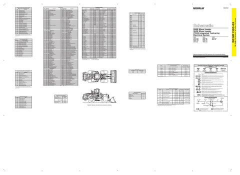
SENR1393-03 February 2011
Connector Location Schematic Location
Machine Location
CONN 1
A-15
53
CONN 2
B-15
43
CONN 3
C-15
54
CONN 4
F-15
55
CONN 5
D-14
44
Connector Number
CONN 6 CONN 7
Monitor Harness Code Plug
CONN 8
A-13
5
H-9, 13
C
F-12
45
CONN 9
E-12
45
CONN 10
D-12
45
C-12
45
CONN 11 CONN 12
Fuse Panel
C-11
C
CONN 13
HVAC Unit
G-10
56
CONN 14
Service Tool Conn.
F-10
C
CONN 15
G-8
B
CONN 16
I-5, 6
51
CONN 17 CONN 18
Xmsn Shift
CONN 19 CONN 20
F-8
A
G-4
A
A-4
D
A-3
46
B-3
45
CONN 22
C-3
58
CONN 23
E-3
A
CONN 24
E-3
A
CONN 25
I-2, 3
51
CONN 26
I-2, 3
52
CONN 27
G-2
47
CONN 21
Left Brake Pedal
CONN 28
F-2
47
CONN 29
C-2
48
CONN 30
E-1
49
CONN 31
E-1
49
CONN 32
F-1
50
CONN 33
G-1
49
CONN 34
G-1
49
CONN 35
I-1
50
H-9
C
CONN 36
Service Mode Plug
950G Wheel Loader 962G Wheel Loader IT62G Integrated Toolcarrier Electrical System 950G: 3JW1-2153 5FW1-1999 5MW1-1077 8JW1-406
Machines Equipped with Pilot Hydraulics and Conventional Steering © 2011 Caterpillar, All Rights Reserved
Resistor, Sender and Solenoid Specifications Component Description
4W-9972
Machine Codes
53 25
4
2 54
55
48 44
8 6 30 3 10 15 32 14 22 33 9 26 17 28 11 21 27 37 13 5 45 36 29 7 43 20 1
A C 57 46 D 59
40
Symbols
110.0° C (230° F) - 72 to 82
3E-6332
Solenoid: Valve - Start Aid
3E-8574
Solenoid: Valve - Ride Control
34.3 ± 1.7
6.0
8C-3663
Solenoid: Engine Shutdown
1.55 ± 0.15
950G
7, 13, 15, 38
106-5122
Solenoid: A/C Clutch
17.6 ± 0.6
962G
14, 16
121-4298
Solenoid: Clutch Modulating Valves
7.75 ± 1.0
129-7707
Solenoid: Dual HP
31.1 ± 2.4
152-5409
Solenoid: Axle Oil Cooler
9G-1950
Resistor: A/C, Heater Blower Motor
10.3 ± 1.03
41 50 12 23 31 39
Hydraulic Oil Temperature
Machine Code
47
56
Sender:
T
Pressure Symbol
49
¹ At room temperature.
Switch (Normally Closed): A switch that will open at a specified point (temp, press, etc.). No circle indicates that the wire cannot be disconnected from the component.
52 24
Ground (Wired): This indicates that the component is connected to a grounded wire. The grounded wire is fastened to the machine.
16
Ground (Case): This indicates that the component does not have a wire connected to ground. It is grounded by being fastened to the machine. Reed Switch: A switch whose contacts are controlled by a magnet. A magnet closes the contacts of a normally open reed switch; it opens the contacts of a normally closed reed switch.
B
D Part No. 3E-6449
59 Monitoring System Mode
A
Payload Control Fault Codes 16800 16801
Fault Battery voltage too high Battery voltage too low
25413
PCS not calibrated
35001
Position sensor out of range
35002
Loss of position sensor signal
36401
Pressure sensor out of range
36402
Loss of pressure sensor signal
76901
Pressure sensor out of range
76902
Loss of pressure sensor signal
81704
Backup battery error
81708
Real time clock not running
82002
Loss of Keypad Data Link
Alternator: 107-7977
SENR4757
Caterpillar Monitoring System Electric Starting Motor:
106-8558
Consist:
106-8557
Consist:
106-8559
SENR1394
SENR3559 SENR3581
Payload Control System
SENR6614
Power Train ECM
SENR1380
5
56
57
45 11 17 13 30 C 22 9 46 43 27 21 2 34 8 29 42 53 16 15 44 37 54 10 26 18 55 48 36 47 6 20 32 25 4 1 7 14 40 28 19 3
Code
Circuit Breaker Symbol
Switch (Normally Open): A switch that will close at a specified point (temp, press, etc.). The circle indicates that the component has screw terminals and a wire can be disconnected from it.
Tap 1.0 ± .05
35
Sender: A component that is used with a temperature or pressure gauge. The sender measures the temperature or pressure. Its resistance changes to give an indication to the gauge of the temperature or pressure.
T
Form Number
Flow Symbol
Overall 2.0 ± .1
² The MID is a diagnostic code that indicates which electronic control module diagnosed the fault.
Title
Level Symbol
Fuse: A component in an electrical circuit that will open the circuit if too much current flows through it.
9.4 ± 5
¹ The CID is a diagnostic code that indicates which component is faulty.
Related Electrical Service Manuals
Temperature Symbol
Symbols and Definitions
38
19
Printed in U.S.A.
Harness And Wire Electrical Schematic Symbols
Resistance (Ohms)¹ 54.0° C (130° F) - 569 to 716
Sales Model
51 58
B
IT62G: AKP1-512 6PS1-UP
CONN 37 Customer Data Conn. C-4 C The connectors shown in this chart are for harness to harness connectors. Connectors that join a harness to a component are generally located at or near the component. See the Component Location Chart.
Part No.
18 42 34
962G: 4PW1-503 6EW1-799 6HW1-414 7BW1-623
52 51 50 41 58 12 24
Mode of Operation Normal
35
31
49
39
Mode Number 0
Harness Code
1
Parameter Display
2
Service
3
Units
4
Calibration
23
3E-6450
Off Machine Switch Specification Function Actuate 38 ± 3° C Start Aid Coolant Temperature (100 ± 5.4° F)
(80.6° F Min.)
Primary Steering Oil Pressure
1200 kPa MAX
700 ± 100 kPa A-C, Normally Closed
Secondary Sterring Oil Pressure
(175 psi MAX)
(100 ± 15 psi)
8270 kPa MAX
6890 ± 345 kPa
A-C, Normally Closed
(1200 psi MAX)
(1000 ± 50psi)
A-B, Normally Open
10700 kPa MAX
8960 ± 345 kPa
A-B, Normally Open
(1500 psi MAX)
(1300 ± 50 psi)
A-C, Normally Closed
275 to 1750 kpa¹
--
(40 to 255 psi)
--
21.0 ± 3.0° C
13.0° C
(69.8 ± 5.4° F)
(55.4° F)
65.0° C ± 3.0
58° C Min.
(149.0° ± 5.4 F)
(136.4° F) Min.
3E-6452
Park Brake Oil Pressure
3E-7693
Service Brake Oil Pressure
114-5333
Refrigerant Pressure (AC)
5, 6, 7 123-2993
Hydraulic Oil Level
38
33
155-8998 155-8999
Machine Harness Connector and Component Locations
Axle Oil Cooler Temperature
Deactuate 27° C Min.
Rear Axle Temperature
125.0° C ± 3.0
117° C Min.
Front Axle Temperature
(257.0° ± 5.4 F)
(242.6° F) Min.
Relay (Magnetic Switch): A relay is an electrical component that is activated by electricity. It has a coil that makes an electromagnet when current flows through it. The electromagnet can open or close the switch part of the relay.
Contact Position Normally Closed
Solenoid: A solenoid is an electrical component that is activated by electricity. It has a coil that makes an electromagnet when current flows through it. The electromagnet can open or close a valve or move a piece of metal that can do work.
A-B, Normally Open Magnetic Latch Solenoid: A magnetic latch solenoid is an electrical component that is activated by electricity and held latched by a permanent magnet. It has two coils (latch and unlatch) that make electromagnet when current flows through them. It also has an internal switch that places the latch coil circuit open at the time the coil latches.
Harness and Wire Symbols
Normally Open ² Normally Closed
Pin
Socket
Wire Color
Wire, Cable, or Harness Assembly Identification A
Normally Closed Normally Closed
¹ With increasing pressure the closed condition can be maintained up to 2800 kpa (405 psi), with decreasing pressure theclosed condition can be maintained down to 170 kpa (25 psi). ² Contact position at the contacts of the harness connector.
Circuit Number Identification
105-9344
Receptacle
Wire Gauge
Ground Connection
Fuse
AA 1
325-PK-14
Single Wire Connector
Component Part Number
Plug 2
200-BK-14
Pin or Socket Number 1 2
Typical representation of a Deutsch connector. The plug contains all sockets and the receptacle contains all pins.
1 2
Typical representation of a Sure-Seal connector. The plug and receptacle contain both pins and sockets.
(Dimensions: 39 inches x 24 inches)
0041
Wire Number
SENR1393-03
(MID²) for Power Train ECM (MID No. 081) CID Component
36 Page,
Wire Description
Component identifiers (CID¹) and Module Identifier