RENR9764-05 April 2012
Harness And Wire Electrical Schematic Symbols CONN 3
CONN 2
Symbols
CONN 1
70
T
50
53
Pressure Symbol
Temperature Symbol
39
Circuit Breaker Symbol
Flow Symbol
Symbols and Definitions Fuse - A component in an electrical circuit that will open the circuit if too much current flows through it.
9
41
Level Symbol
Switch (Normally Open): A switch that will close at a specified point (temp, press, etc.). The circle indicates that the component has screw terminals and a wire can be disconnected from it.
40
Switch (Normally Closed): A switch that will open at a specified point (temp, press, etc.). No circle indicates that the wire cannot be disconnected from the component.
7
31
Ground (Wired): This indicates that the component is connected to a grounded wire. The grounded wire is fastened to the machine. Ground (Case): This indicates that the component does not have a wire connected to ground. It is grounded by being fastened to the machine.
26
2
Reed Switch: A switch whose contacts are controlled by a magnet. A magnet closes the contacts of a normally open reed switch; it opens the contacts of a normally closed reed switch.
35
52
Volume 1 - Off Machine Switch Specification
T
Part No.
Function
114-5333
A/C (High/Low) Pressure
313-5104
Primary & Secondary Steering Pressure
314-2405
Low Brake Oil Pressure
Actuate 275 to 1750 kPa¹ (39.9 to 253.8 psi) 1,200 kPa MAX (174 psi MAX) 10,700 kPa MAX (1552 psi MAX)
Deactuate -
Contact Position
700 ± 100 kPa (102 ± 14.5 psi) 8,960 ± 537 kPa (1300 ± 78 psi)
A-B Normally Open A-C Normally Closed A-B Normally Open A-C Normally Closed
Normally Open²
Relay (Magnetic Switch): A relay is an electrical component that is activated by electricity. It has a coil that makes an electromagnet when current flows through it. The electromagnet can open or close the switch part of the relay.
66 CONN 9
¹ With increasing pressure the closed condition can be maintained up to 2800 kpa (405 psi), with decreasing pressure the closed condition can be maintained down to 170 kpa (25psi).
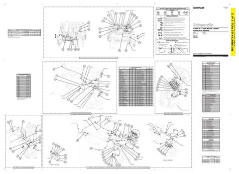
938H: MCC1-UP MJC1-UP JKM1-UP LKM1-UP
Solenoid: A solenoid is an electrical component that is activated by electricity. It has a coil that makes an electromagnet when current flows through it. The electromagnet can open or close a valve or move a piece of metal that can do work.
CONN 8
33
938H & IT38H Wheel Loader Electrical System
Sender: A component that is used with a temperature or pressure gauge. The sender measures the temperature or pressure. Its resistance changes to give an indication to the gauge of the temperature or pressure.
MAGNETIC LATCH SOLENOID - A magnetic latch solenoid is an electrical component that is activated by electricity and held latched by a permanent magnet. It has two coils (latch and unlatch) that make electromagnet when current flows through them. It also has an internal switch that places the latch coil circuit open at the time the coil latches.
² Contact position at the contacts of the harness connector.
IT38H: JNJ1-UP
Harness and Wire Symbols 1 2
36
1 2
Deutsch connector: Typical representation of a Deutsch connector. The plug contains all sockets and the receptacle contains all pins.
Harness Identification Letter(s): (A, B, C, ..., AA, AB, AC, ...)
Wire, Cable, or Harness Assembly Identification: Includes Harness Identification Letters and Harness Connector Serialization Codes
Harness Connector Serialization Code: The "C" stands for "Connector" and the number indicates which connector in the harness. (C1, C2, C3, .....)
Part Number for Connector Plug
C-C4 AG-C3 130-6795 130-6795
10
13
80
77
1
74
5A
Receptacle Pin or Socket Number
Single Wire Connector
CONN 4
Part Number For Connector Recepticle
Socket
Pin
44
L-C12 3E-5179
AG-C4 111-7898
325-AG135 PK-14
21
Sure-Seal connector: Typical representation of a Sure-Seal connector. The plug and receptacle contain both pins and sockets.
9X-1123
Component Part Number
Plug
200-L32 BK-14
2
Harness identification code: This example indicates wire 135 in harness "AG".
Fuse (5 Amps)
Ground Connection
Circuit Identification Number
Wire Gauge
Wire Color
Volume 1 of 2: Engine & Chassis Wiring © 2012 Caterpillar, All Rights Reserved
Printed in U.S.A.
(CH) HARNESS - ENGINE APPLICATION HARNESS & (PE) HARNESS - BASIC ENGINE HARNESS
Component Identifiers (CID¹) Module Identifier (MID²) Engine Control System (MID No. 036)
34 91
Schematic Location
CONN 1
D-17
CONN 2
D-17
CONN 3
D-17
CONN 4
F-15
CONN 5
G-15
CONN 6
K-16
CONN 7
L-16
CONN 8
72
15
73 CONN 24
E-13
CONN 9
E-13
CONN 10
C-9
CONN 11
J-8
CONN 12
E-6
CONN 13
G-6
CONN 14
I-6
CONN 15
G-4, K-4
CONN 16
CONN 26
43
H-2
CONN 17
H-2
CONN 18
H-2
CONN 19
I-2
CONN 20
J-2
CONN 21
J-2
CONN 22
K-2
CONN 23
CONN 22
D-4, K-2
CONN 24
L-2
CONN 25
D-2
CONN 26
L-2
CONN 27
L-2
42
The connectors shown in this chart are for harness to harness connectors. Connectors that join a harness to a component are generally located at or near the component. See the Component Location Chart.
Schematic Location
Machine Location
0004
Cylinder #4 Injector
Alarm - Backup
I-17
1
Sensor - Torque Converter Oil Temperature
H-7
49
0005
Cylinder #5 Injector
Alternator
J-15
2
Sensor - Wastegate
D-18
50
0006
Cylinder #6 Injector
51
0041
8 Volt DC Supply
Battery
J-12
3
Sensor - XMSN Pump Pressure
H-7
Breaker - Buss (Cab)
H-13
4
Solenoid - A/C Clutch
H-16
52
0091
Throttle Position Sensor
Breaker - Glow Plugs
G-13
5
Solenoid - Axle Oil Cooler Clutch
G-16
53
0100
Engine Oil Pressure Sensor
Breaker - Main
H-13
6
Solenoid - Clutch # 3 (Reverse)
I-7
54
0110
Engine Coolant Temperature Sensor
0168
Battery Voltage
Control - Engine
E-16
7
Solenoid - Clutch #1 (Forward Low)
J-7
55
Control - Hood Raise/Lower Motor
I-11
8
Solenoid - Clutch #2 (Forward High)
J-7
56
0171
Ambient Air Temperature Sensor
Glowplugs 1-6
G-16
9
Solenoid - Clutch #4 (Speed #2)
I-7
57
0172
Intake Air Temp Sensor
Ground - Engine Block
I-16
10
Solenoid - Clutch #5 (Speed #3)
I-7
58
67
J-11
11
Solenoid - Clutch #6 (Speed #1)
I-7
59
12
Solenoid - Differential Lock (Front)
B-10
60
0261
Engine Timing Calibration
Ground - LH Frame Starter
I-15
13
Solenoid - Differential Lock (Rear)
B-10
61
0262
5V DC Sensor Supply
Ground - Secondary Steering
J-11
14
Solenoid - Differential Lock Actuation
C-10
62
Horn - Forward (938H)
L-2
15
Solenoid - Fan Brake Load Bypass
I-9
63
Horn - Forward (IT38H)
G-1
16
Solenoid - Fan Pump
F-16
64
Motor - Autolube Pump
L-1
17
Solenoid - Fan Valve
F-16
65
Motor - Fuel Priming Pump
G-15
18
Solenoid - Fuel Pump
D-18
Motor - Hood Actuator
I-17
19
Solenoid - Implement Pilot Shutoff (938H)
I-2
55 54
0267
Remote Shutdown Input
0268
Programed Parameter Fault
0291
Engine Cooling Fan Solenoid
0296
Transmission Control
66
0342
Sec Engine Speed Sensor
67
0526
Turbo Wastegate Actuator
1438
Engine Cooling Fan Solenoid #2
Motor - Secondary Steering
J-10
20
Solenoid - Implement Pilot Shutoff (IT38G)
F-1
68
Motor - Starter
J-15
21
Solenoid - Implement Power Management
A-9
69
Motor - Washer Pump (Front)
K-9
22
Solenoid - Injector 1-6
D-17
70
Motor - Washer Pump (Rear)
K-9
23
Solenoid - Quick Coupler
I-1
71
57 CONN 14
59
1639
Mach Sec System ECM
1779
Fuel Rail Pressure Valve Solenoid
1785
Intake Manifold Pressure Sensor
1797
Fuel Rail Pressure Sensor
Relay - Glowplug
G-13
24
Solenoid - Ride Control #1
H-2
72
Relay - Main
H-13
25
Solenoid - Ride Control #2
H-2
73
1834
Ignition Key Swtich
Resistor - CAN Datalink (Engine)
E-14
26
Solenoid - Start Aid
F-15
74
1849
Engine Fan Reverse Relay
Sender - Fuel Level
K-16
27
Solenoid - Variable Speed Fan
B-10
75
2246
Glow Plug Start Aid Relay
Sender - Hydraulic Oil Temperature
E-7
28
Solenoid - XMSN Pump Flow Bypass
I-9
76
Sender - Rear Axle Oil Temperature
J-15
29
Suppressor - HVAC Arc
H-16
77
Sender - XMSN Oil Temperature
J-7
30
Suppressor - Quick Coupler Arc
H-1
78
Sensor - Ambient Air Temperature
F-15
31
Suppressor - Secondary Steering Arc
J-10
79
Sensor - Articulation Angle
H-9
32
Switch - A/C Pressure
H-16
80
Sensor - Cam Speed
E-18
33
Switch - Bucket Position (IT38H)
F-1
81
J-7
34
Switch - Bucket/Tilt Position (938H)
K-2
82
E-18
35
Switch - Case Drain Filter
B-10
E-18
36
Switch - Disconnect
J-12
I-1
37
Switch - Fork Position (IT38H)
G-1
85
Sensor - Front Wheel Speed (RH)
I-1
38
Switch - Front Axle Oil Monitoring
J-2
86
D-18
39
Switch - Fuel Priming Pump
G-15
87
Sensor - Intake Manifold Pressure
E-18
40
Switch - Ground Level Shutdown
I-11
88
E-18
41
Switch - Hood Actuator
I-11
89
Sensor - Lift Cylinder Head End Pressure
K-2
42
Switch - Hydraulic Filter Bypass
C-10
90
Sensor - Lift Position
K-2
43
Switch - Lift Position (938H)
L-2
91
44
Switch - Lift Position (IT38H)
H-1
I-7
45
Switch - Low Brake Oil Pressure
Sensor - Output Speed (Trailing)
I-7
46
Switch - Steering Pressure (Primary)
K-9
94
Sensor - Rear Wheel Speed (LH)
L-17
47
Switch - Steering Pressure (Secondary)
K-9
95
L-17
48
Switch - XMSN Filter Bypass
C-10
45
¹ The CID is a diagnostic code that indicates which circuit is faulty. ² The MID is a diagnostic code that indicates which electronic control module diagnosed the fault.
Failure Mode Identifiers (FMI)¹
46
92
Sensor - Output Speed (Leading)
Sensor - Rear Wheel Speed (RH)
C-10
58
84
Sensor - Intake Manifold Temperature
D-18
51
83
Sensor - Front Wheel Speed (LH)
Sensor - Oil Pressure
CONN 18
Engine Speed Sensor Personality Module
K-12
Sensor - Fuel Rail Pressure
CONN 15
0190 0253
Ground - Frame
Sensor - Crank Speed
17
56
Ground - LH Frame
Sensor - Coolant Temperature
CONN 27
Cylinder #2 Injector Cylinder #3 Injector
Component
Sensor - Converter Output Speed
CONN 16
0002 0003
Machine Location
Component
Connector Location (Volume 1)
Cylinder #1 Injector
Schematic Location
CONN 20
82
Component
0001
Component Location (Volume 1)
CONN 23
Connector Number
CID
49
CONN 17
93
96
CONN 21 CONN 19 TRANSMISSION AR
FMI No.
Failure Description
0
Data valid but above normal operational range.
1
Data valid but below normal operational range.
2
Data erratic, intermittent, or incorrect.
3
Voltage above normal or shorted high.
4
Voltage below normal or shorted low.
5
Current below normal or open circuit.
6
Current above normal or grounded circuit.
7
Mechanical system not responding properly.
8
Abnormal frequency, pulse width, or period.
9
Abnormal update.
10
Abnormal rate of change.
11
Failure mode not identifiable.
12
Bad device or component.
13
Out of calibration.
14
Parameter failures.
15
Parameter failures.
16
Parameter not available.
17
Module not responding.
18
Sensor supply fault.
19
Condition not met.
20
Parameter failures.
¹The FMI is a diagnostic code that indicates what type of failure has occurred.
(AG) HARNESS - 938H FRONT FRAME HARNESS
(AT) HARNESS - TRANSMISSION HARNESS LH TAIL LAMPS
1 27
64
Event Code
CONN 6
81
65
92
85
Event Codes Engine Control
NOT SHOWN
CONN 7
NOT SHOWN
0194
28
RH TAIL LAMPS
CONN 12
CONN 9
29
CONN 23
47
11
CONN 8
CONN 13
12
79
78
24 89
CONN 11
5
30
3
B
48 6
CONN 15
High Engine Coolant Temperature Engine Overspeed
0396
High Fuel Rail Pressure
0398
Low Fuel Rail Pressure
0441
Idle Elevated to Increase Batt Voltage
0539
High Intake Manifold Air Temperature
1044
High Intake Manifold Pressure
1045
Low Intake Manffold Pressure
0049
Coasting in Neutral Warning
0284
Low Brake Accumulator Pressure
0329
Transmission Filter Plugged
0454
Hydraulic Case Drain Filter Plugged
0490
Park Brake On - Not In Neutral
0627
Parking Brake On - Machine In Motion
0861
Clock Manual Alignment Required
0878
High Hydraulic Oil Temp
0879
Hydraulic Tank Oil Filter Plugged
2129
High Front Axle Temp
2130
High Rear Axle Temp
0643
86
68
0361 0362
Event Codes Payload Control
19
4
User Defined Shutdown Low Engine Oil Pressure
Event Codes Machine Control
22
71
0265 0360
23
A
16
Condition High Exhaust Temperature
Lift Pressure Change During Weigh
0783
Machine Pitched or Bucket Tilted
0784
Weight too heavy to zero
1027
Lift Too Slow To Weigh
1028
Lift Stopped During Weigh
1042
Excessive Lift Speed Change
1043
Lift Too Jerky During Weigh
2083
Payload Memory Low
2138
Payload Memory Full
Event Codes Product Link Control
14 0861
20
69
Zero Timer Expired
0782
Manual Clock Alignment Required
94 25
37
8
38
32
83 76
90
VIEW OF AREA (A) (AC) HARNESS - IT38H FRONT FRAME HARNESS
88
Related Electrical Service Manuals
NOT SHOWN
Title Alternator:
63
75 84
95
NOT SHOWN
93 96
62
61
60
CONN 10
(CJ) HARNESS - MAIN CHASSIS HARNESS, (CV) HARNESS - SECONDARY STEERING HARNESS & (HC) HARNESS - HYDRAULIC SERVICE CENTER HARNESS
VIEW OF AREA (B)
Form Number 235-7132 (65A) Std 235-7133 (80A) Atch
SENR4130
Engine Control System:
KENR5392
Machine Control System:
RENR8999
Machine Monitoring System:
RENR6319
Payload Control System:
SENR6614
36 Page,
18
RENR9764-05 VOL 1 of 2
87
(Dimensions: 48 inches x 35 inches)
CONN 5