Electrical Schematic Symbols And Definitions Component Identifiers (CID¹) Traction Control System (MID² 028) 168 248 263 270 296 605 606 607 608 609 610
Electrical System Voltage Data Link Sensor Supply Voltage Harness Code Transmission ECM Left Front Speed Sensor Right Front Speed Sensor Left Rear Speed Sensor Right Rear Speed Sensor Left Front Brake Solenoid Right Front Brake Solenoid
611
Left Rear Brake Solenoid
612
Right Rear Brake Solenoid
613
On/Off Solenoid
615
Articulation Sensor
616
Test/Enable Switch
653
Traction Control System ECM
687
Options Code Plug
Off Machine Switch Specification Part No.
Function
Actuate
Deactuate
Contact Position
-1.1 ± 0.8°C 2.2 ± 0.8°C Normally Open (30 ± 1.4°F) (36 ± 1.4°F) 38 ± 3°C 27°C MIN 3E-6449 Coolant Temperature (Start Aid) Normally Closed (100 ± 5°F) (81°F MIN) Primary Steering Pressure 1200 kPa MAX 700 ± 100 kPa A-B Normally Open 3E-6450 (174.0 psi MAX) (102 ± 14.5 psi) A-C Normally Closed Secondary Steering Pressure 129 ± 4°C 96°C MIN 104-3007 ² Torque Converter Oil Temperature Normally Open (264 ± 7°F) (205°F MIN) 102 ± 3°C 90°C MIN 104-3008 ² Hydraulic Oil Temperature Normally Open (216 ± 5°F) (194°F MIN) 275 to 1750 kPa¹ 114-5333 A/C (High / Low) Pressure Normally Open³ (39.9 to 253.8 psi) 107 ± 3°C 95°C MIN 118-5144 ² Coolant Temperature Normally Open (225 ± 5°F) (203°F MIN) 65 ± 3°C 58°C MIN 155-8998 Axle Oil Cooler Temperature Normally Open (149 ± 5°F) (136°F MIN) 10700 kPa MAX 8960 ± 537 kPa A-B Normally Open 175-3244 Brake Oil Pressure (1552 psi MAX) (1300 ± 78 psi) A-C Normally Closed ¹ With increasing pressure the closed condition can be maintained up to 2800 kPa (406 psi), with decreasing pressure the closed condition can be maintained down to 170 kPa (25 psi). ² This part has an integral temperature sender. See also Resistor, Sender and Solenoid Specifications. ³ Contact position at the contacts of the harness connector. 3E-5464
Component
CID
Resistor, Sender and Solenoid Specifications Part No.
Resistance (Ohms)¹
3E-8575
Solenoid:
Quick Coupler
8C-3663
Solenoid:
Shutdown
9G-1950
Resistor:
Blower Motor
104-3007 ²
Sender:
Torque Converter Oil Temperature
104-3008 ²
Sender:
Hydraulic Oil Temperature
106-5122
Solenoid:
118-5144 ²
Sender:
122-6344
Solenoid:
Auxiliary Valve Float Valve Lift Positioner Valve Tilt Positioner Valve
85.3 ± 5
124-3052
Solenoid:
TCS Left Front Proportional Valve TCS Left Rear Proportional Valve TCS Right Front Proportional Valve TCS Right Rear Proportional Valve
7.8 ± 1.0
134-7262
Sender:
A/C Thermostat
¹ The CID is a diagnostic code that indicates which component is faulty. ² The MID is a diagnostic code that indicates which electronic control module diagnosed the fault.
Component Identifiers (CID¹) Payload Control System (MID² 74)
Component Description
SENR6679-02 February 2001
A/C Clutch
24.9 ± 0.4 Latch Coil: 1.55 ± 0.16 Unlatch Coil: 10.3 ± 1.0 Overall: 2.0 ± 0.1 Tap: 1.0 ± 0.05 54.4°C (130°F): 6565 ± 695 115.6°C (240°F): 526 ± 61 54.4°C (130°F): 6565 ± 695 115.6°C (240°F): 526 ± 61
T
Pressure Symbol
Normally open switch that will close with an increase of a specific condition (temp-press-etc.). The circle indicates that the component has screw terminals and a wire can be disconnected from it.
17.6 ± 0.6 54.4°C (130°F): 6565 ± 695 115.6°C (240°F): 526 ± 61
Coolant Temperature
Normally closed switch that will open with an increase of a specific condition. No circle indicates that the wire cannot be disconnected from the component. This indicates that the component has a wire connected to it that is connected to ground.
This indicates that the component does not have a wire connected to ground. It is grounded by being fastened to the machine.
Empty: 250 ± 10 Full: 33.5 ± 6
Fuel Level
149-2658
Solenoid:
Ride Control
32.6 ± 1.6
152-8351
Solenoid:
4th Function Diverter
32.6 ± 1.6 32.6 ± 1.6
152-8385
Solenoid:
TCS Pilot On/Off
168-6452
Solenoid:
Axle Oil Cooler
9.4 ± 5
186-1526
Solenoid:
CST Transmission Valve (Qty=6)
31 ± 3
Reed Switch - A switch whose contacts are controlled by a magnet. A magnet closes the contacts of a normally open reed switch; it opens the contacts of a normally closed reed switch.
168
Electrical System Voltage
254
Payload Electronic Control Module
350
Position Sensor (Lift Linkage)
364
Pressure Sensor (Lift Cylinder Head End)
769
Pressure Sensor (Lift Cylinder Rod End)
817
Battery (Internal Backup)
820
T
² This part has an integral temperature switch. See also Off Machine Switch Specification.
¹ The CID is a diagnostic code that indicates which component is faulty. ² The MID is a diagnostic code that indicates which electronic control module diagnosed the fault.
Component Identifiers (CID¹) CST Autoshift Control (MID² 081) Component
CID
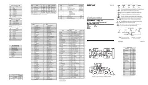
938G Wheel Loader and IT38G Integrated Toolcarrier Electrical System
Wire Description
Keypad Data Link Incorrect
Wire Number
Wire Color
101
RD
Wire Number
Wire Color
Battery (+)
502
OR
Wiper - Front (Hi) Wiper - Rear (Park)
Description Power Circuits
RD
Running Lamp Breaker
503
BR
105
RD
Key Switch
504
YL
Wiper - Rear (Low)
108
RD
24V to 12V Converter Memory Output
505
BU
Wiper - Rear (Hi)
109
RD
Alt Output (+) / Main Brkr / Alt Brkr / Start Rly
506
PU
Washer - Front
112
PU
Main Power Rly Output
507
WH
Washer - Rear
Electrical System Voltage
114
RD
Warning Horn (Forward)
508
PU
Radio Speaker - Left
190
Engine Speed Sensor
115
RD
Running Lamp Breaker/Spare Circuit
509
WH
Radio Speaker - Left (Common)
191
Transmission Output Speed Sensor
116
BR
Rear Floods
511
BR
Radio Speaker - Right
346
Ride Control Relay
117
RD
Main Power Relay
512
GN
Radio Speaker - Right (Common)
367
Ride Control Switch
118
GY
Wipers
513
OR
A/C Compressor/Refrigerant Pressure SW
120
YL
24V to 12V Converter
515
GY
Blower Motor (Hi)
421
Load Check Solenoid
122
RD
Backup Alarm / Misc Power
516
GN
Blower Motor (Medium)
621
Downshift Switch
123
WH
Gauges / Indicator Lights
517
BU
Blower Motor (Low)
641
Forward High Solenoid
124
GN
HVAC
521
YL
A/C SW To Refrigerant SW
Reverse Solenoid
125
OR
Axle Oil Cooler
522
WH
A/C Clutch To Thermostat SW
PK
CST Autoshift Control / Shifter
938G: 4YS1-1877 6WS1-2578 8RS1-UP 9HS1-800
Accessory Circuits (Continued)
102
126
537
GN
Turn Signal SW To Flasher
E-11
Machine Location 2
Alarm
G-8
C
Alarm - Backup
D-15
3
Alarm - Secondary Steering
G-8
Alternator
Component Air Conditioner
Batteries - 12 Volt
Schematic Location
D-15
Machine Location 35
Sender - Fuel Level
E-15
36
Sender - Hydraulic Oil Temp
C-14
37
A
Sender - Torque Converter Oil Temp
C-13
38
E-15
4
Sensor - Engine Speed
C-14
39
F-14
5
B-2,E-1
21
Sensor - PCS Lift Position
C-2,E-1
22
A-4
23
B-2,E-1,G-1
24
I-6
25
A-2,D-1,G-1
26
Component Sender - Coolant Temp
Sensor - PCS Lift Cyl Head End Oil Press
127
OR
Floods
538
BR
Hazard Indicator
Breaker - Air Seat
F-10
C
644
Speed 1 Solenoid
128
PK
Kickout / Ride Control
567
WH
A/C SW Jumper
Breaker - Alternator
B-14
47
Sensor - TCS Articulation Angle Position
645
Speed 2 Solenoid
129
BU
Cigar Lighter
571
OR
Ride Control Relay Coil
Breaker - Auxiliary
B-14
47
Sensor - TCS Left Front Wheel Speed
646
Speed 3 Solenoid
130
RD
Stop Lamps
A514
YL
CST Control To Park Brake Alarm Relay Coil
Harness Code
4th Function Diverter
A538
OR
Rear Window Defroster (Resistive Element In
Sensor - TCS Left Rear Axle Speed
650
OR
B-14
47
133
Breaker - Hood Breaker - Lamp
F-10
C
Sensor - TCS Right Front Wheel Speed
668
Transmission Shift Lever
683
Parking Brake Alarm
687
Option Code
24V to 12V Converter Switched Output
A576
GN
Breaker To Compressor (Air Seat)
Schematic Location
136
GN
Secondary Steering / Action Alarm
C529
GY
Lift Head End Pressure Sensor
Breaker - Main
B-14
C
Sensor - TCS Right Rear Axle Speed
I-6
27
138
GN
Payload Control System (PCS)
C530
BU
Lift Position Sensor
Cigar Lighter
E-7
A
Sensor - Transmission Speed
C-13
39
140
BU
Rear Window Defrost
Control - Autoshift Electronic (CST)
A-7
7
Service Meter
G-6
A
¹ The CID is a diagnostic code that indicates which component is faulty.
144
GN
Heated Seat / Beacon
603
PK
Rotary Beacon
604
OR
Stop Lamp
H-1
² The MID is a diagnostic code that indicates which electronic control module
Air Intake Heater Relay
Solenoid - 4th Function Pilot Diverter
21
PU
A-14
8
160
Control - Hood Relay
167
OR
Transmission Control System (TCS)
605
YL
Turn Lamp - Left
Control - Payload Electronic (PCS)
E-4
12
Solenoid - A/C Clutch
C-15
6
diagnosed the fault.
168
GN
Quick Coupler
606
GY
Turn Lamp - Right
Control - Secondary Steering Electronic
B-6
7
Solenoid - Axle Oil Cooler Clutch
D-14
44
175
RD
Hood Relay Control
608
GN
Flood Lamp - Rear Cab
Control - Traction Electronic (TCS)
A-12
9
Solenoid - Countershaft Transmission
D-13
31
188
WH
PCS Keypad
610
OR
Head Lamp (Basic)
Control - Transmission Shifter (CST)
H-6
B
Solenoid - Quick Coupler
189
WH
Air Intake Heater (AIH)
611
PU
Head Lamp (High)
Converter - 24 Volt to 12 Volt
G-10
34
Solenoid - Ride Control
614
PU
Park/Tail/Panel Lamp
Defroster - Rear
F-12
17
Ground Circuits
Failure Mode Identifiers (FMI)¹ FMI No. 0 1 2 3 4 5 6 7 8 9 10 11 12 13 14 15 16 17 18 19 20
Failure Description Data valid but above normal operational range. Data valid but below normal operational range. Data erratic, intermittent, or incorrect. Voltage above normal or shorted high. Voltage below normal or shorted low. Current below normal or open circuit. Current above normal or grounded circuit. Mechanical system not responding properly. Abnormal frequency, pulse width, or period. Abnormal update. Abnormal rate of change. Failure mode not identifiable. Bad device or component. Out of calibration. Parameter failures. Parameter failures. Parameter not available. Module not responding. Sensor supply fault. Condition not met. Parameter failures.
Traction Control System Transmission Electronic Control System
C-15
28
E-13
29
BK
Main Chassis
615
YL
Flood Lamp - Forward Cab
XMSN Ctrl
617
BR
LH Tail/Clearance Lamps
Diode Block Assembly
H-8
A
Solenoid - Start Aid
250
BK
Payload Mon - Customer Gnd
619
GN
Head Lamp (Lo)
Flasher
F-6
A
Solenoid - TCS Left Front Proportional
I-5
30
251
BK
Payload Mon - System Gnd
630
GY
Flood Lamp Rear (Attach)
Flasher - German Roading (COSA Opt)
I-7
A
Solenoid - TCS Left Rear Proportional
I-5
30
276
BK
XMSN Ctrl Ident Code 0
667
OR
Front Floods - Aux
Flasher (Japan Option)
I-7
A
Solenoid - TCS On/Off Pilot
I-4
30
277
BK
XMSN Ctrl Ident Code 1
Fuses
F-10
C
Solenoid - TCS Right Front Proportional
I-5
30
Gauge - Coolant Temp
G-4
A
Solenoid - TCS Right Rear Proportional
I-5
30
Suppressor - Arc (A/C Clutch Coil)
C-15
6
G-10
7
BK
XMSN Ctrl Ident Code 2
Control Circuits 702
OR
XMSN Brake SW Jumper
279
BK
XMSN Ctrl Ident Code 3
709
OR
Sensor Power Supply
A219
BK
TCS Ctrl Gnd
710
GN
XMSN Speed Sensor
Gauge - Fuel Level
F-4
A
A221
BK
XMSN Ctrl Options Code 0
720
PU
XMSN Neutralizer Override Switch
Gauge - Hydraulic Oil Temp
G-5
A
Suppressor - Arc (Alarm Disarm Relay)
Gauge - Speedometer
F-4
A
Suppressor - Arc (Quick Coupler Sol)
B-2
33
A222
BK
XMSN Ctrl Options Code 1
727
GN
Secondary Steering Relay Coil
A223
BK
TCS Ctrl Harness Code 0
751
GN
XMSN Clutch No. 1 - FWD High
A224
BK
TCS Ctrl Harness Code 1
752
YL
XMSN Clutch No. 2 - REV
F-5
A
Suppressor - Arc (Sec Str Mtr Rly)
A-6
19
A225
BK
TCS Ctrl Harness Code 2
754
BU
XMSN Clutch No. 3 - FWD Low
Ground - Cab Boss
B-12
7
Switch - (TCS) Test Enable
E-8
A
A226
BK
TCS Ctrl Harness Code 3
755
OR
XMSN Clutch No. 4 - SPD 1
Ground - Engine Block (from AIH)
E-13
10
Switch - 4th Function Pilot Diverter
E-8
D
Ground - Engine Block (from Alternator)
D-15
4
Switch - A/C Compressor
F-8
D
A232
BK
XMSN Ctrl Options Code 2
761
GY
Lift Positioner Switch
A250
BK
Bat (-)
762
YL
Bucket Positioner Switch
A279
BK
TCS Ctrl Harness Code 4
779
WH
Quick Coupler (Engage Sol)
A280
BK
TCS Ctrl Harness Code 5
E701
PK
Ride Control Switch (Auto)
Gauge - Torque Converter Oil Temp
Ground - Engine End Frame
15
Switch - Air Inlet Heater
10
Switch - Axle Oil Cooler Temp
E-11
18
Switch - Beacon
BK
TCS Ctrl Harness Code 6
F748
WH
Ride Control Switch (On)
BK
Switch/Sensor Ground
F765
BR
Park Brake Switch
Heater - Cab
Kickout Override Sw (N/O)
301
BU
Shutdown Solenoid (Start Coil)
G728
YL
Kickout Override Sw (N/C)
304
WH
Starter Solenoid Start Terminal
G742
GN
Alarm/Disarm Relay to Diode
306
GN
Starter Relay Coil (+)
G750
BU
XMSN Cont Forward Switch
307
OR
Key Switch Start Position
G755
GY
308
YL
Main Power Relay Coil (+)
G760
310
PU
Start Aid SW To Start Aid Sol
G761
311
WH
Start Aid Sol To Start Aid Coolant Temp SW
G762
321
BR
Backup Alarm
G763
PU
XMSN Cont Neutral Switch
322
GY
Warning Horn (Forward)
G768
GN
XMSN Cont (First Gear)
Switch - A/C Refrigerant (Press)
A-12
A282
WH
32
E-13
A281
F766
F-14
Ground - Frame Boss Heater - Air Inlet
Basic Machine Circuits
Horn - Forward Keypad - Payload Control System (PCS)
C-2,F-2,I-1
11
Switch - Blower
D-4
12
Switch - Brake Oil Press
C-15 F-7
A
A-14
47
F-7
A
F-9
D
C-3,F-3,I-3
43
C-2,E-1,H-1
D
F-8
D
Switch - Defrost
F-8
D
Switch - Dimmer
F-6
B
A
Switch - Disconnect
F-14
32
D-7
61
Switch - Downshift
B-8
D
F-5
A
Switch - Engine Oil Press
C-14
40
Lamp - Action
B-8
7
Switch - Bucket Positioner
XMSN Cont Reverse Switch
Lamp - Alternator
C-7
A
Switch - Bucket/Fork Select
WH
XMSN Cont (Second Gear)
Lamp - Brake Oil Press
H-7
A
YL
XMSN Cont (Third Gear)
Lamp - Coolant Temp
G-7
A
BR
XMSN Cont (Fourth Gear)
Lamp - Engine Oil Press
H-7
Lamp - Flood Lamp
326
RD
Key Switch Off Position
G787
GN
XMSN Cont Remote Forward Switch
Lamp - Hazard
331
OR
Backup Alarm Relay Coil
G788
YL
XMSN Cont Remote Reverse Switch
Lamp - High Beam
F-5
A
Switch - Fork Positioner
H-1
D
334
BU
AIH Relay Coil (+)
818
BR
Serial Data (Transmit)
Lamp - Hydraulic Oil Temp
H-7
A
Switch - Forward Horn
F-6
B
373
GN
AIH Switch to AIH Timer
819
GY
Serial Data (Receive)
Lamp - Left Turn
F-5
A
Switch - Front Intermittent Wiper
D-7
A
397
OR
Hood Motor Lower
E800
GN
Seat Alarm To Diode Pack
Switch - Hood Actuator
398
BU
Hood Motor Raise
F853
BR
Travel Speed
Lamp - Park Brake
D-7
A
A-14
8
A300
GN
Hood Control Lower
G878
GY
Traction Control System (TCS) Calibrate
Lamp - Primary Steering Oil Press
D-7
A
Switch - Hydraulic Lock Detent Override
F-8
A
A301
WH
Hood Control Raise
900
PU
XMSN Clutch No. 5 - SPD 2
Lamp - Right Turn
F-5
A
Switch - Key Start
F-6
B
901
WH
XMSN Clutch No. 6 - SPD 3
Lamp - Secondary Steering Oil Press
D-7
A
Switch - Kickout
E-8
D
OR
Data Link + (CAT)
Lamp - Transmission Oil Temp
G-7
A
Switch - Lamp
H-7
A
GN
Alternator (R) Term.
944
404
YL
Hyd Oil Temp Switch
945
BR
Data Link - (CAT)
405
GY
Engine Oil Pressure Switch
963
GN
Bucket/Fork Position Detent Coil
Module - (TCS) Display
406
PU
Engine Coolant Temp Switch
964
BU
Fork Position Select
Motor - Front Washer
407
PK
T/C Oil Temp Switch
973
BR
CST Autoshift- Auto/Manual Switch
Motor - Front Wiper
417
GY
Primary Steering Pressure Switch (N/O)
975
441
OR
Engine Coolant Temp Sender
976
442
GY
Hyd OIl Temp Sender
978
WH
D-5
13
Switch - Lamp Test
G-7
A
C-3,F-2,I-2
15
Switch - Lift Positioner
C-2,E-1,H-1
33
E-4
16
Switch - Parking Brake
G-10
45
CST Autoshift- Sol Return
Motor - Heater/Air Conditioner Blower
OR
Ride Cont Sol
Motor - Hood Actuator
A-14
1
GN
CST Autoshift- Slow Mode SW 1
Motor - Rear Washer
C-3,F-3,I-3
15
F-12
17
Switch - Ride Control
E-11
18
Switch - Primary Steering Oil Press
A-6
42
Switch - Quick Coupler
F-8
D
Switch - Rear Wiper
C-7
A
E-8
D
443
YL
T/C Oil Temp Sender
987
WH
Diverter Sol
447
PK
Fuel Level Sender
C920
GY
Fault Lamp - Control
Motor - Rear Wiper
449
BU
Speedometer Sender
E923
PK
Front Left Wheel Proportional Solenoid
Motor - Secondary Steering Pump
A-6
19
Switch - Secondary Steering Manual
D-7
A
450
YL
Engine Speed Sensor
E924
YL
Front Right Wheel Proportional Solenoid
Motor - Starter
E-14
14
Switch - Secondary Steering Oil Press
A-6
42
453
PK
Secondary Steering Pressure Switch (N/O)
E925
OR
Rear Left Wheel Proportional Solenoid
Relay - Air Inlet Heater
E-13
20
Switch - Service Brake
C-4
41
Relay - Alarm Disarm
D-11
C
Switch - Start Aid
D-8
A
BR
Brake Oil Pressure Switch (N/C)
E926
BU
Rear Right Wheel Proportional Solenoid
484
YL
Primary Steering Pressure Switch (N/C)
E927
GN
Test Mode SW (N/C)
C444
YL
Alternator D+ Term
E928
WH
Test Mode SW (N/O)
Relay - Backup Alarm
D-10
C
Switch - Start Aid Coolant (Temp)
D-15
44
C445
BU
Alarm To Diode Pack
E929
GY
Articulation Angle Sensor
Relay - Main Power
F-10
C
Switch - Thermostat
E-11
18
C470
BR
Relay Contact To Alarm
E930
BU
Front Axle Pilot Solenoid
Relay - Park Brake Alarm
D-10
C
Switch - Transmission Auto/Manual
D-8
D
C471
GN
Relay Contact To Indicator Lamp
E932
PK
Front Left Wheel Speed Sensor
Relay - Rear Flood
B-13
C
Switch - Transmission Neut Override
F-7
A
Form Number
E416
PU
PCS Lift Cyl Press Sensor
E933
YL
Front Right Wheel Speed Sensor
OR
Park Brake Switch (N/C)
E934
OR
Rear Left Wheel Speed Sensor
D-10
C
Switch - Transmission Neutralizer
C-4
46
SENR3685 SENR4757
E417
Relay - Ride Control
E419
BU
Relay Contact to Seat Alarm
E935
GN
Rear Right Wheel Speed Sensor
Relay - Seat Alarm
D-10
C
Switch - Turn Signal
F-6
A
G454
PK
Axle Oil Cooler Sw to Clutch Solenoid
E936
WH
TCS Solenoid Return
Relay - Secondary Steering Motor
A-6
C
Terminal Block
E-14
7
G476
WH
Traction Control Action Indicator
E955
OR
Keypad Data
Relay - Start
B-14
C
Timer - Air Inlet Heater
G-8
A
G486
GN
Not Used
P914
GN
Used For 924G and 928G Only
Resistor - Heater/Air Conditioner
E-11
D
Valve - Pilot Control
B-9
D
P915
PK
Used For 924G and 928G Only
500
BR
Wiper - Front (Park)
P916
OR
CST Shifter Neutral Sw Signal
501
GN
Wiper - Front (Low)
P976
BR
Quick Coupler (Disengage Sol)
SENR3859 SENR3581 SENR6614 SENR6719 SENR1218
Accessory Circuits
Harness And Wire Symbols
Socket
Wire Color
Machine locations are repeated for components located close together. A = Located on or near dash panel. B = Located on or near steering column. C = Located on or near relay / fuse panel. D = Located on or near right console.
Circuit Number Identification
105-9344
Receptacle
Wire Gauge
Ground Connection
Fuse
AA 1
325-PK-14
Single Wire Connector
Component Part Number
Wire, Cable, or Harness Assembly Identification A
Plug 2
200-BK-14
Pin or Socket Number 1 2
Typical representation of a Deutsch connector. The plug contains all sockets and the receptacle contains all pins.
1 2
Typical representation of a Sure-Seal connector. The plug and receptacle contain both pins and sockets.
©2001 Caterpillar All Rights Reserved
Printed in U.S.A.
Connector Location Connector Number
61
5
57 34 45 49 51 29 43 50
25 32
35
4
58
14
30 15
33
38 60 37
36 59
3
17
2
18
B
A
31
D
52
47
42
16
56
46
39 48 6 40
21
41
23
44 28
1
24
11
10
20
6
483
Related Electrical Service Manuals 9W-3043 107-7977 106-8558 106-8557 106-8559
21
Solenoid - Shutdown
BK
403
Alternator: Atch: Electric Starting Motor: Consist: Consist: Payload Control System
33
202
Monitoring Circuits
Title
B-2 C-2,F-1,I-1
200
278
¹ The FMI is a diagnostic code that indicates what type of failure has occurred.
Lighting Circuits
IT38G: 7BS1-899 1CW1-390 Pin
Forward Low Solenoid
BU
Solenoid - A solenoid is an electrical component that is activated by electricity. It has a coil that makes an electromagnet when current flows through it. The electromagnet can open or close a valve or move a piece of metal that can do work.
Component Location
643
135
Relay (Magnetic Switch) - A relay is an electrical component that is activated by electricity. It has a coil that makes an electromagnet when current flows through it. The electromagnet can open or close the switch part of the relay.
Description
168
642
Sender- A component that is used with a temperature or pressure gauge. The sender measures the temperature or pressure. Its resistance changes to give an indication to the gauge of the temperature or pressure.
¹ At room temperature unless otherwise noted.
Component
CID
Circuit Breaker Symbol
Flow Symbol
Level Symbol
Temperature Symbol
C
8
55
54 12 13
53
27
7 19
61
53
61
22
26
9
49 52
50
17 57 12
B 37 35
20 44 4
3
10
38
40
5
8
32 58
36
42
39 14
59 25 27
47
13 51 41
34 C 18
29
6 28
1
D 2 45
48
A
43
9
7
16
33 22
46 11 31
19 23
15
60
21 55
30 54 24 26 56
E99248
Machine Harness Connector And Component Locations
Schematic Location
Machine Location
CONN 1 D-15 39 CONN 2 D-15 3 CONN 3 Aux Start Receptacle F-14 58 CONN 4 C-14 6 CONN 5 A-13 40 CONN 6 C-13 48 CONN 7 E-12, I-9 18 CONN 8 D-12, I-9 52 CONN 9 Aux 12V Power D-12 53 CONN 10 C-12 7 CONN 11 C-12 7 CONN 12 B-12 7 CONN 13 TCS Calibrate Plug B-11 7 CONN 14 A/C and Heater E-11 18 CONN 15 F-11 2 CONN 16 F-11 2 CONN 17 H-10 50 CONN 18 Aux 12V Power Socket G-10 51 CONN 19 G-10 34 CONN 20 G-10 C CONN 21 B-10 7 CONN 22 TCS Code Plug A-12, B-10 7 CONN 23 Options Plug A-8, I-8 7 CONN 24 Machine Harness Code A-8, I-8 7 CONN 25 Service Tool (ECAP/ET) A-8 7 CONN 26 I-6 59 CONN 27 G-6 A CONN 28 G-6 A CONN 29 E-6 A CONN 30 E-6 A CONN 31 E-6 A CONN 32 D-6 A CONN 33 A-6 7 CONN 34 A-5, B-2 7 CONN 35 A-5, E-3, H-3 7 CONN 36 B-5, E-3, H-3 7 CONN 37 G-5 A CONN 38 G-4 A CONN 39 PCS Data Connection D-4 A CONN 40 D-4 12 CONN 41 D-4 12 CONN 42 C-4 41 CONN 43 A-3, E-2 57 CONN 44 D-2, G-2, I-2 55 CONN 45 D-2, G-2, I-2 55 CONN 46 C-2, F-2, I-2 55 CONN 47 B-2 60 CONN 48 H-2 55 CONN 49 E-2, G-2 56 The connectors shown in this chart are for harness to harness connectors. Connectors that join a harness to a component are generally located at or near the component. See the Component Location Chart.